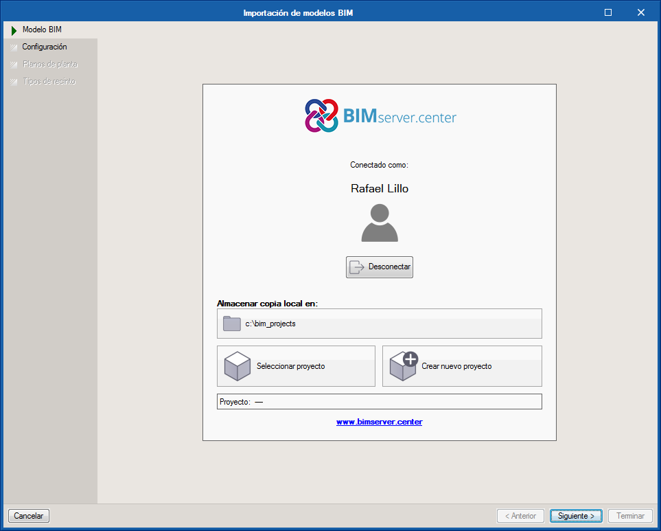
Users must register on the BIMserver.center web platform to be able to use the application. Once the program has been downloaded and installed, as well as the BIMserver.center synchroniser, new projects created by users must have a project lodged on the platform, which will allow the collaborative Open BIM workflow to take place.
CYPELEC Networks can be downloaded from the BIMserver.center platform and can currently be installed in Spanish and English.
Design method
To obtain the characteristic values of the installation (voltages, currents and powers), the program establishes a matrix analysis of the system based on the connections between the elements it is composed of. The physical properties of each impedance element will define the values of the admittance matrix of the system, and the consumption properties in the loads and generation properties in the supply sources will define the operating conditions of the system.
The calculation of the voltages of the nodes and the power fluxes for all the elements of the electrical system is done using the Newton-Raphson method. This method obtains the results through successive iterations of the matrix resolution, and stops the process when the power functions are less than the maximum allowed error.
Thanks to the matrix analysis of the system and the convergence method used for the calculation, the program allows users to introduce any distribution of interconnected elements, this way offering fully optimised computation speeds, and a level of precision in the results that can be configured by users.
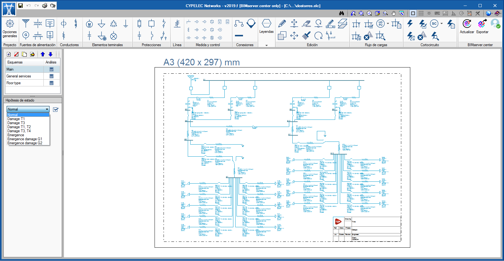
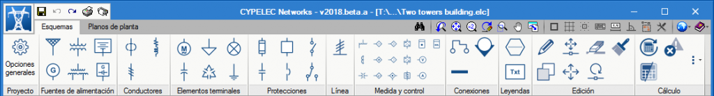
Workspace
The program is divided into two spaces, which are represented by two tabs:
Diagrams
Floor plans
Editing the parameters of the drawing
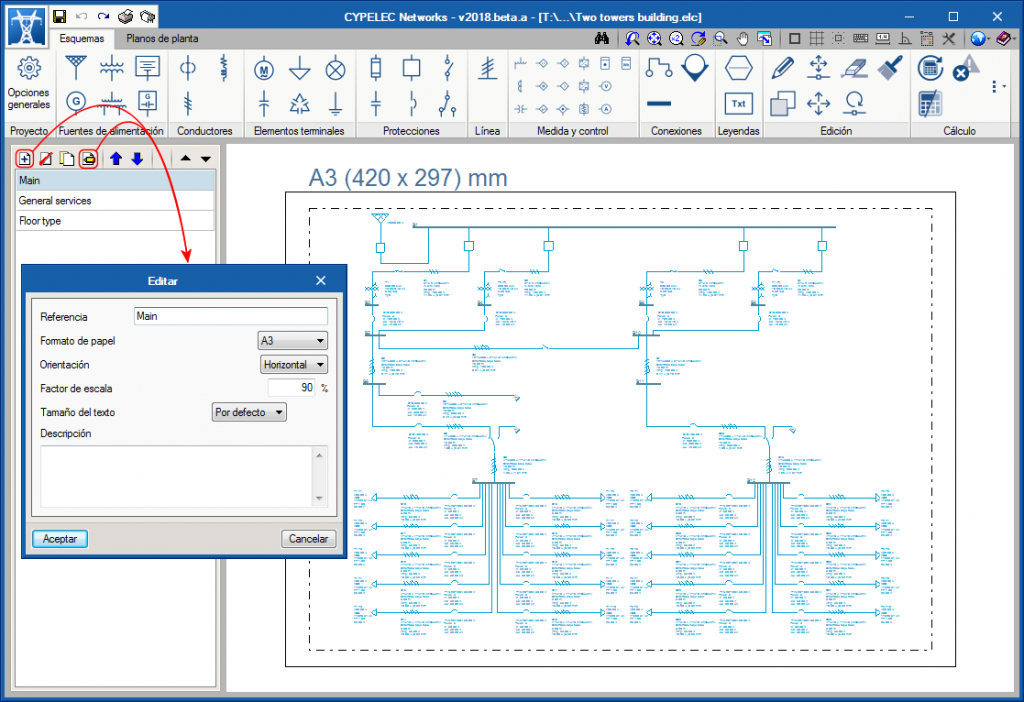
From both tabs (Diagrams and Floor plans), the program allows users to generate independent drawings to define the diagrams that make up the installation and floor plans. The appearance properties can be configured for each drawing of the diagrams so they are printed to the format selected by users and the font size is adjusted so texts are adequately visible. To do so, the following options are available:
Drawing title Identifies each drawing using a text reference.
Description Allows users to introduce a small descriptive text associated with the contents of the drawing.
Paper size Users can choose between DIN or ANSI format.
Drawing orientation The orientation can be changed from Vertical to Horizontal and vice-versa.
Text size Using this scale, the size of the texts can be modified with respect to the dimensions of the element they describe.
Scale factor It affects all the elements displayed on the drawings (elements, connections and texts), so the general dimensions of the diagram can be adjusted so the limits of the paper are not exceeded.
“Diagrams” tab
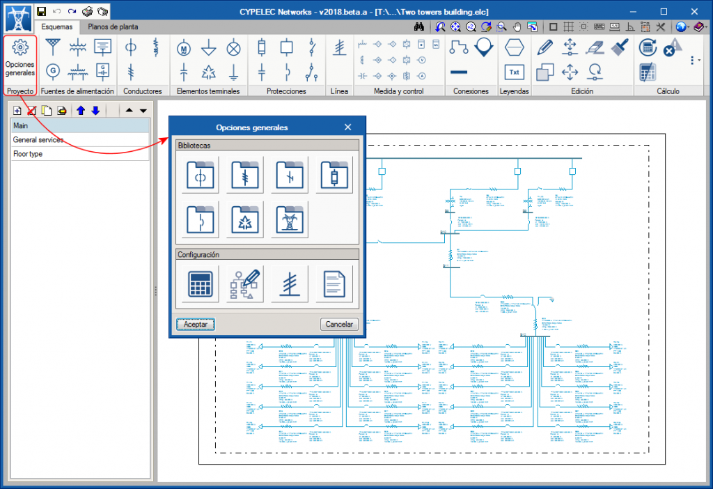
General settings
Libraries
The program offers a selection of devices whose properties are stored in different element libraries. The properties of each element are defined from the catalogues of the main manufacturers in the sector, however, these libraries can be completely edited by users, who can also modify parameters or add new elements if desired. The program has the following libraries:
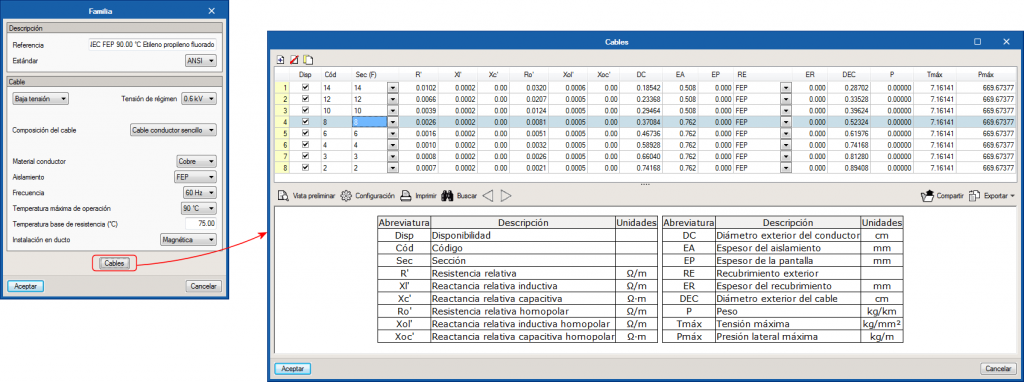
Cables
Transmission lines
Earth cables
Fuses
Circuit breakers
Capacitor banks
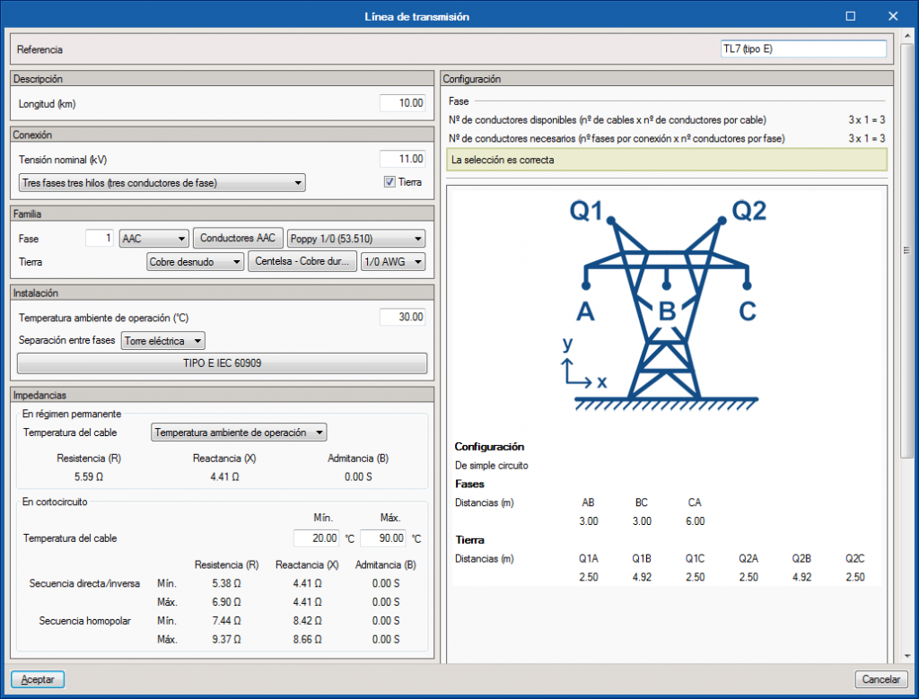
Configuration of transmission lines (Transmission towers)
Configuration
Design options Here, users can modify parameters such as the network frequency, the base power for the conversion to the PU system, the maximum number of iterations and the maximum allowable error allowed for the iterative design.
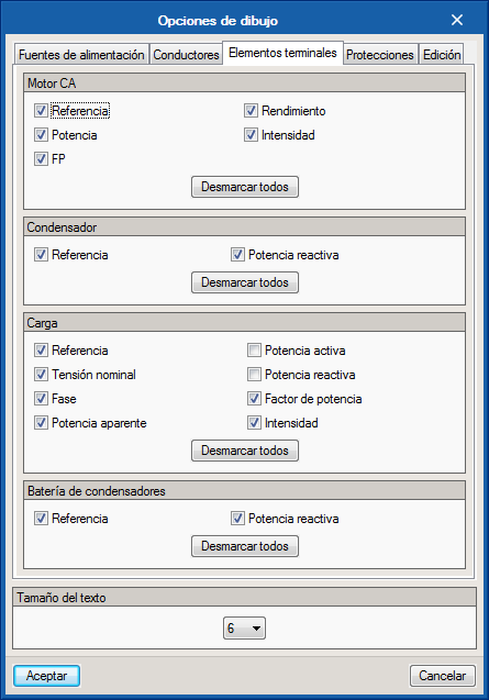
Drawing options With this option, users can activate or deactivate the fields that appear in the labels of each element of the drawing, as well as the font size of all the texts.
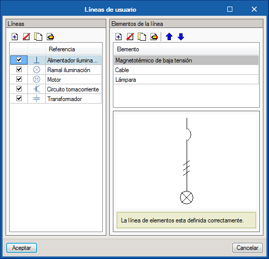
User lines This tool allows users to configure lines of several elements simultaneously for them to be introduced at the same time on the plan. Each element must be defined with its corresponding library reference to incorporate its design properties. How these predefined lines in the elements bar are viewed is controlled from this function, as well as the icon that is used for their selection.
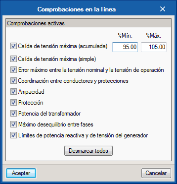
Line checks The program carries out a series of design checks that can be selected by users. Using this option, the application limits of the global checks can be defined, and activate or deactivate them depending on users’ criteria.
Supply sources
The following power supplies can be introduced:
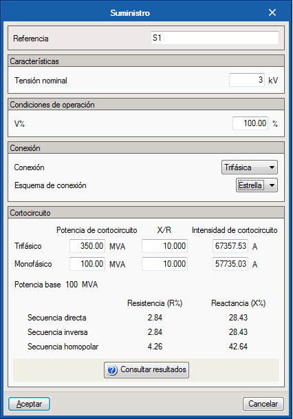
Supply The supply source is the starting point of the installation. The supply voltage of the network is established at the supply source, which will then be the base voltage of the installation, its connection properties and short-circuit properties. At least one supply source must be introduced in all the electrical projects.
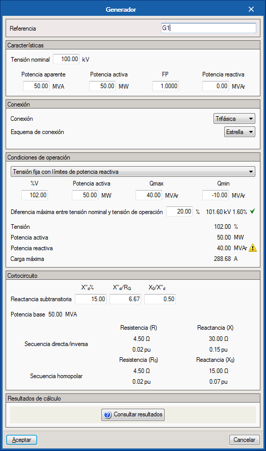
Generator The supply source may be accompanied by one or more generators installed along the electrical installation. For the generators, their nominal, connection and short-circuit properties are introduced. A noteworthy aspect of generators is the definition of their operation mode. The operation mode of the generator can consist of maintaining a fixed voltage by regulating the reactive power or by keeping the reactive power fixed in which case the voltage between a minimum and maximum value is regulated.
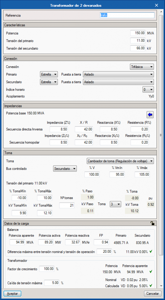
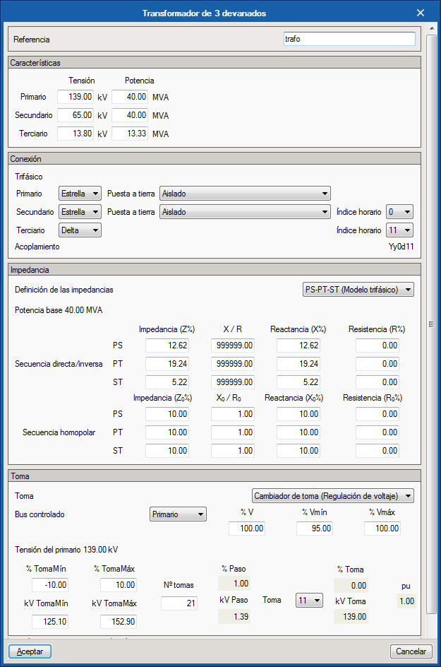
Two and three winding transformers Two and three winding transformers allow for the voltage and connection in their respective windings to be varied and adjusted. A feature of the transformers is the possibility of configuring the tap in order to regulate the voltage in the buses connected to the windings of the transformer.
Battery and photovoltaic generator These are drawing elements to complete the diagram.
Conductors
The available types of conductors are:
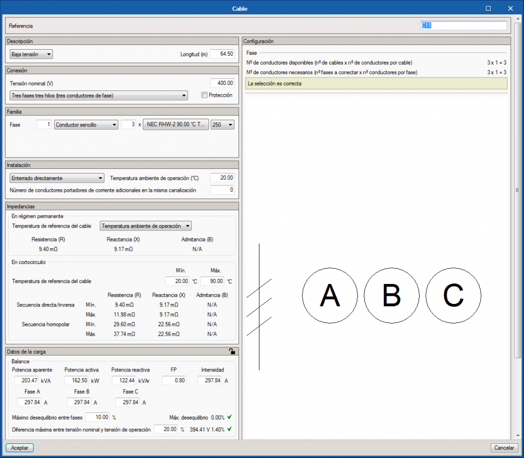
Cables The selection of the chosen cable model is done so starting with the families defined in the library. The program will take the physical properties of the selected cable, and the user must define its installation conditions. This way, using the tables defined in the standard, the maximum admissible current for each conductor will be obtained as well as the impedances that are required for the voltage and current calculations.
Regarding the configuration of the conductors, the panel offers all the possible combinations to be able to select the properties of the power cables; single conductors, multi-conductor cables of different combinations (2x, 3x, 4x, 5x ...), triplex cables, for both low voltage and medium voltage. The properties of the cable together with the installation method determine the series impedance and the parallel admittance of the cable, which are required to calculate the load flow of the installation, and therefore the current. This current compared to the ampacity of the cable determines if the cable is valid.
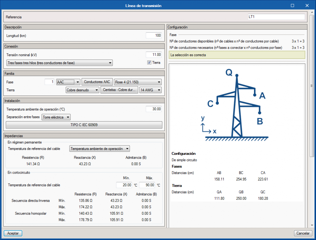
Transmission lines As occurs with cables, the program offers great versatility to select conductors that form the high voltage transmission line, including the possibility of locating these conductors on typical electrical towers.
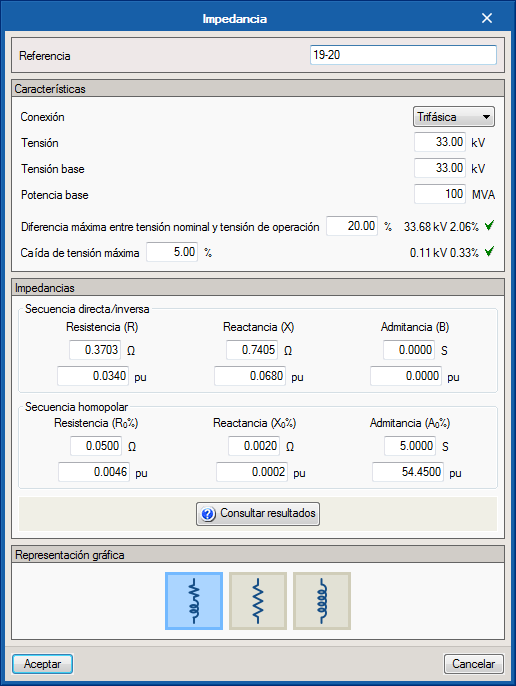
Impedances As well as cables and transmission lines, users can incorporate impedances in PU values or in Ohms.
Terminal elements
The terminal elements provided by the program are:
Loads Loads can be introduced by indicating their power consumption (apparent, active and reactive) or by indicating their current consumption so that any value introduced modifies the rest of the parameters.
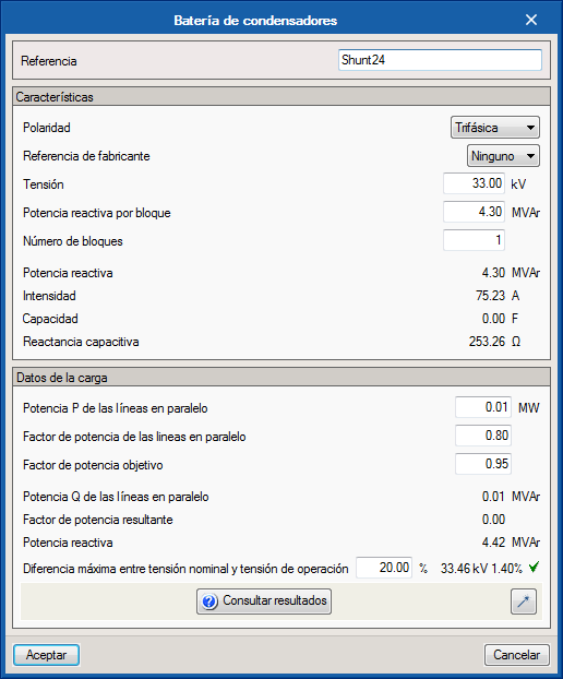
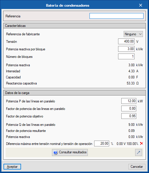
Capacitors and capacitor banks Capacitors and capacitor banks are defined by the contribution of capacitive reactive energy in the electrical system with the aim of improving the power factor.
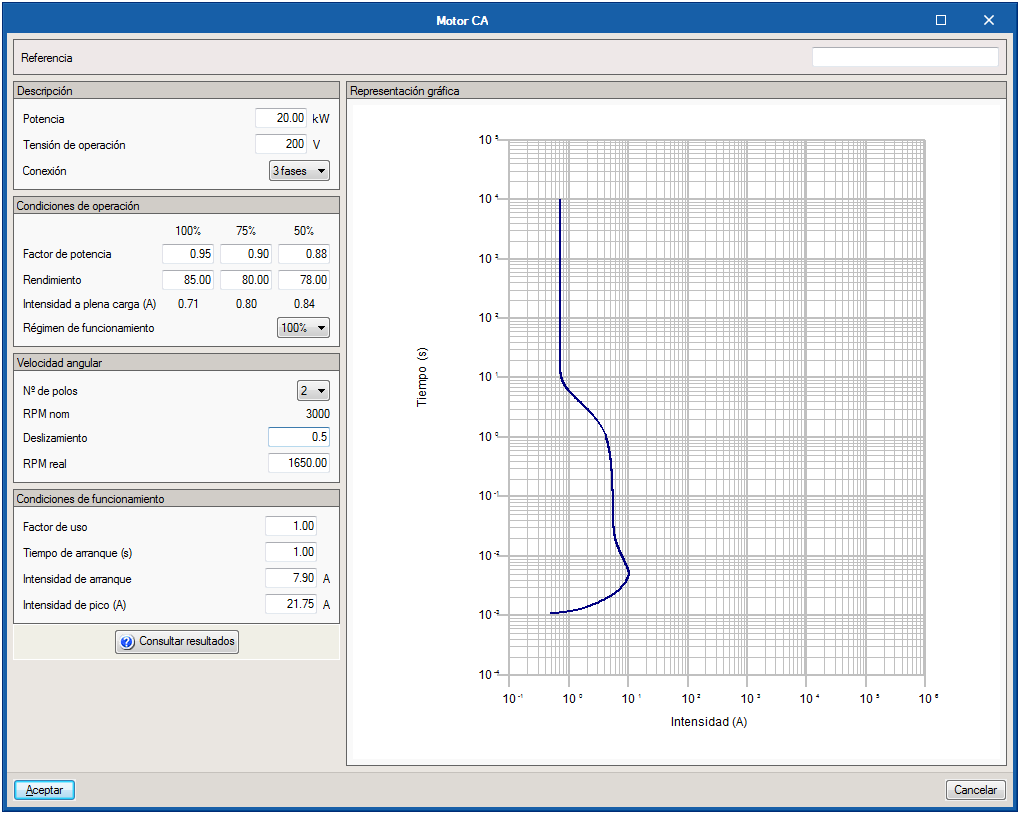
Motors The motor panel allows users to define the operating properties to obtain results of the current that is consumed depending on the selected operating regime and the moment after starting.
Hence, in the description of the motor, its power, the nominal voltage for which it is designed and the type of power supply (single-phase or three-phase) have to be defined.
Three operating regimes can be established for the operating conditions (100%, 75% or 50% of the full load) and users must choose for which of them the equipment works. Depending on the selected mode, the required current will be obtained, from which the operating and starting curve will be drawn.
In "angular velocity", the RPM calculation is carried out according to the number of poles and the machine's slip.
Lastly, in the "Operating Conditions", the critical parameters for starting the motor, such as the peak current, the inrush current or the starting time are established. With all the data correctly defined, the program shows the motor start curve in a Current-time graph on a logarithmic scale. This graph will be transferred to the protection of the motor to correctly select the device and guarantee the protection is not triggered during the initial moments of the start.
Lamps Drawing elements to complete the diagram.
Ground Drawing elements to complete the diagram.
Protection
The protection elements that can be introduced in the program are:
High-voltage circuit breakers Drawing element to complete the diagram.
Contactors Opening and closing elements which allow for the continuity of the system to be modified at different parts of the diagram.
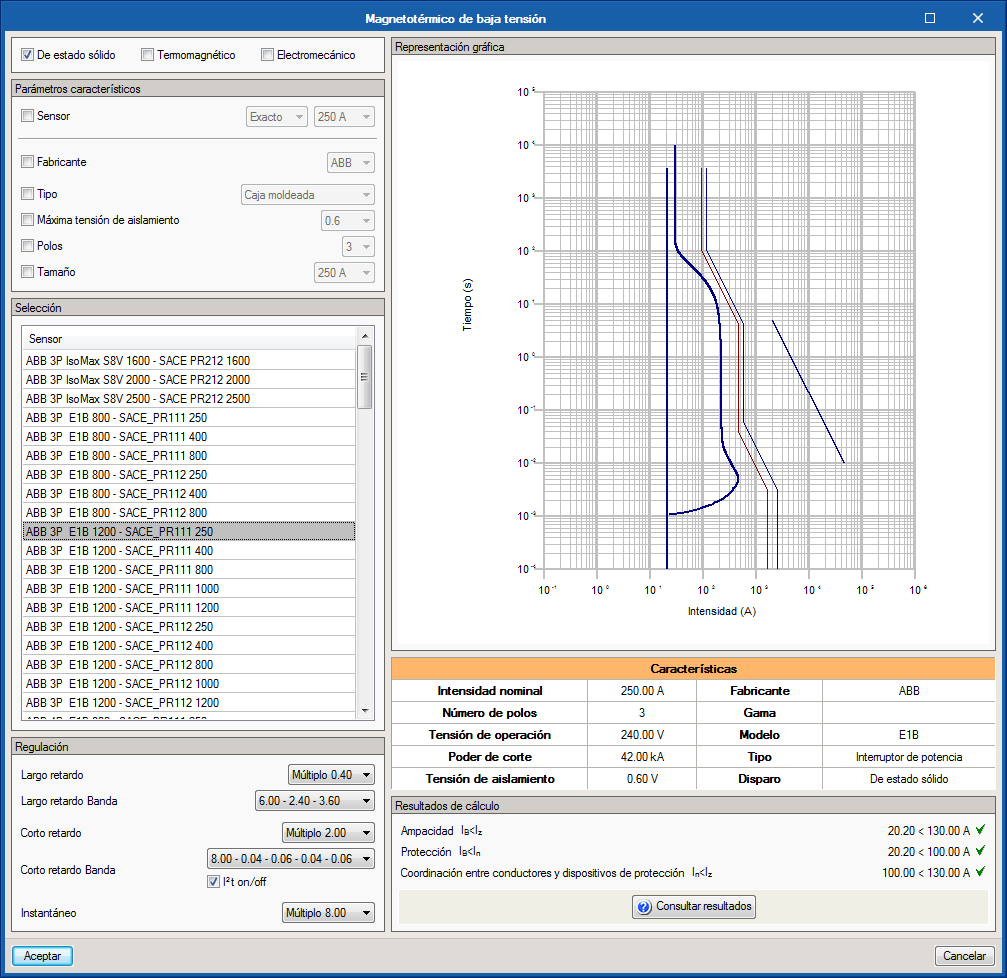
Low voltage circuit breakers The selection panel of low voltage circuit breakers is structured so that the selection of the equipment is carried out based on manufacturer references that have been imported into the library. To do so, the program has a parameter properties filter in which different properties can be activated or deactivated in such a way that the list of selected equipment is reduced to that which meets the requirements sought by users.
Below the selection list are the regulation parameters for the devices for which that functionality has been enabled.
The properties of the selected device are summarised in a properties table located next to the trigger curve of the device. It is updated when the regulation is modified, so it is possible to perform a visual check of the coordination and selectivity limits with cables and motor loads, whose performance curves can be seen on the same graph window.
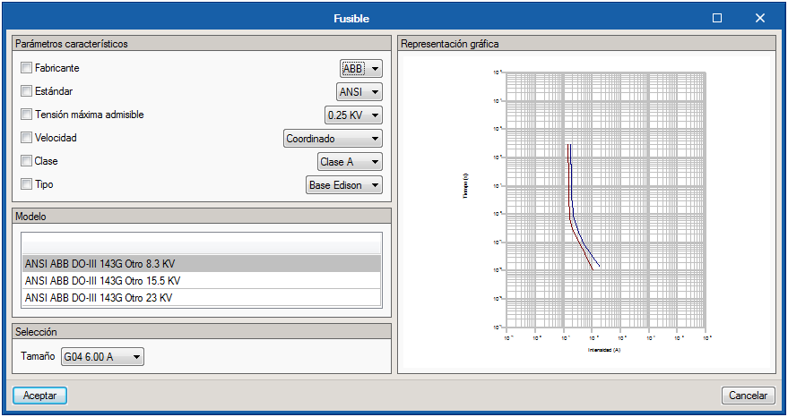
FusesThe fuse selection panel is very similar to that of the circuit breakers.It has a parameter properties filter, a list of models, and finally a selection of the selected size within the model. The characteristic curve of the chosen fuse is shown on the graph situated to the right of the panel.
Contacts and transfer contacts Elements that open or close the passage of current in the span of the installation where they are located.
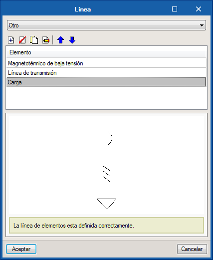
Element lines
In order to offer users a more dynamic introduction of the elements, the "Line" tool has been designed. With it, it is possible to configure different blocks of elements for their joint introduction on the plan. The selector includes lines that were previously defined in the configuration options, however it is possible to add more elements to each line, or even generate a group of elements starting from scratch. The modifications made to the element blocks from this button will not affect those defined in the line library. To store lines in the library, users must go to the corresponding section of the configuration options.
As well as the general button for the introduction of predefined lines, the program offers a series of quick accesses to these lines, which have been previously configured by users. Its display in the toolbar depends on its activation in the configuration options.
Measurement and control elements
This block includes a series of drawing elements to complete the diagram without the need of having to define its electrical properties. It consists of:
Autotransformers
Current transformers
Voltage transformers
Overcurrent relays
Motor relays
Differential relays
Thermal relays
Magnetic relays
Multifunction relays
Inverters
Rectifiers
Harmonic filters
Multi-meters
Voltmeters
Ammeters
Watt hour meter
Connections
This group of buttons includes functionalities related with interconnection aspects of the elements that make up the installation:
Connection Allows users to draw a polyline to joint elements to one another. When establishing connections between elements, a help tool will be activated and the terminals of elements that are susceptible of being connected to the initial element will be highlighted.
Bus Introduces a bar to which different elements can be connected. For design purposes, it behaves as a node, so each bus will have a results label with the value of its operating voltage.
Continuation point It is an element that connects different points of the diagram, or different diagrams, to perform the integral calculation of the installation without having to include it in the same plan. To do this, one of these elements must be placed at each point to be joined, assigned the same reference and continue the design as if both points were directly connected.
Keys
The following keys can be installed in the installation diagram:
Identifier Label that can be configured to mark the voltage level as well as a three-letter reference for each diagram or part of the diagram.
Editing tools
Edit It is the work mode activated by default and allows users to open the property panels of the equipment to modify their properties.
Copy Allows users to copy selected elements to a new location on plan.
Move Moves a single element to a new location on plan. Users can also use this tool to act on connection elements and modify the length of connections and buses.
Move a group of elements Moves selected elements to a new location on plan.
DeleteDeletes the selected elements from the plan.
Rotate Allows users to rotate elements about a selected rotation axis.
Match Tool that allows users to match the properties of an element to those of the rest of its class. To do so, click on the reference element then on those to which the copied information is to be applied. Elements that are susceptible of being modified will be highlighted to help users located them.
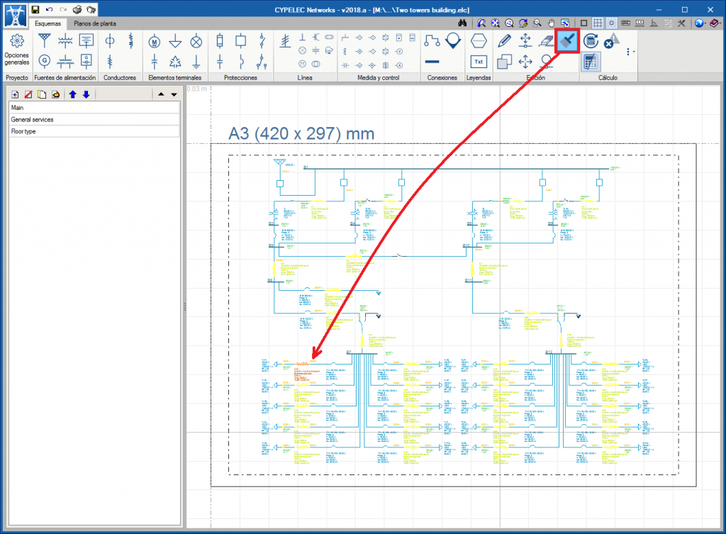
Load flow
The load flow block contains the following tools:
Update results Launches the analysis motor of the program to obtain results and evaluate the limits established for each magnitude.
Show/hide results Activates or deactivates the warnings and errors display on the diagram.
Checks Displays a table showing which elements have check errors. The table lists the type of element, its reference, the failure conditions, the check limit that has been introduced, the operation value of the evaluated magnitude and the difference between the limit and operation conditions.
Results Allows users to change the view of the results represented on the diagram, from the PU value to the magnitude next to its unit.
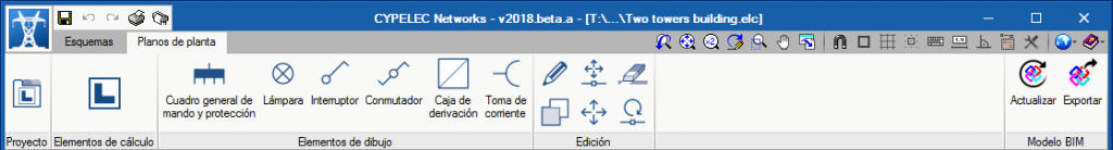
“Floor plans” tab. Open BIM workspace
In addition to the "Diagrams" tab, CYPELEC Networks includes a "Floor plans" tab where the design of the installation on CAD templates or geometry import of a BIM model can be carried out.
Using this tab, users can interact with the rest of the elements that make up the installation, importing both the geometry of the building and the electrical equipment defined in other programs, such as, for example, lights or equipment with power consumption.
Licenses and related modules
CYPE programs are activated via electronic licenses which may contain one or more modules. The list of modules compatible with each program may vary depending on the product purchased and the type of license.
To consult the list of modules compatible with this program, go to "CYPE program modules".
Please note that the list of modules available in the license will depend on the product purchased.