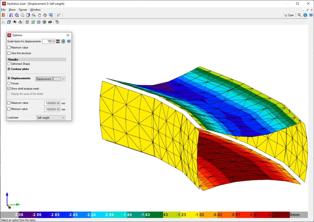
Completed discretisation
The design model used is a 3D thick-shell triangular finite element type, which considers shear deformation. These elements are formed by six nodes located at the vertices and midpoints of the sides with six degrees of freedom each. A box culvert mesh is generated based on its dimensions (thickness, spans and applied loads).
Consults the stress isodiagrams, displacement isodiagrams and the deformation drawing for any load hypothesis in a 3D view.
The module’s foundation is assumed as a slab supported on an elastic soil with springs at the nodes (ballast coefficient method , according to Winker’s model, based on a proportionality constant between forces and displacements, whose value is the ballast coefficient. This loadcase is valid for homogeneous soils. The ballast modulus is a parameter to be entered into the program. This is determined through empirical methods with a load plate test. Typically, a geotechnical study should provide the exact value of this modulus for the dimensions of the foundation slab.
The wingwall is designed as a cantilevered element. However, if the length of the wingwall is large, the reinforcement is divided into several spans (the minimum length for each span is defined in the design options) and each span will have a different footing size. In the case of variable wall height, each span is discretised into 2-metre-long vertical strips (measured in the floor plan) for the reinforcement. The reinforcement design is based on the worstcase scenario for the largest strip, and this design is applied to the entire wall corresponding to the same segment. For the stability analysis, to stop the wingwalls from overturning and sliding, a single result is obtained for the entire elevation, and it is checked against the entire footing, not the individual strips.
Continuous footing is designed under the wingwall, which can have various configurations: with both toe and heel, only toe, or only heel.
Analysis method
To obtain the loads, the principles of rational mechanics have been considered along with the classical theories of material resistance and elasticity.
The applied analysis method follows limit state principles. The aim is to ensure that the effect of external loads, weighted by certain coefficients, does not exceed the structure’s response, accounting for reduced material strengths (following EHE, RSA, REBAP, and BAEL standards).
For ultimate limit states, checks are made for equilibrium, fatigue, or rupture.
In the states of serviceability, checks are made for deformations (deflections), stresses on the soil and slab separations.
Once the load states have been defined according to their origin, the possible combinations are analysed with the corresponding increase and decrease coefficients, based on the safety factors and basic loadcases defined in the standards.
To determine forces under different simple loadcases, analyses are performed using first-order linear analysis, assuming proportionality between stresses and deformations, the principle of action superposition, and linear geometric behaviour of materials and structure.
To obtain the determining stresses in the element design, the envelopes are obtained for each stress.


