Analysis, checks and designs
In the "Analysis" group of the main toolbar, either on the "Single-line" tab or on the "Tree" tab, there are options for analysing, checking and designing the system:

Analysis
Clicking on this option launches all the code-checking processes implemented by the program. This internally checks whether the parameters that have been entered to design the system are within the criteria permitted by the current codes.
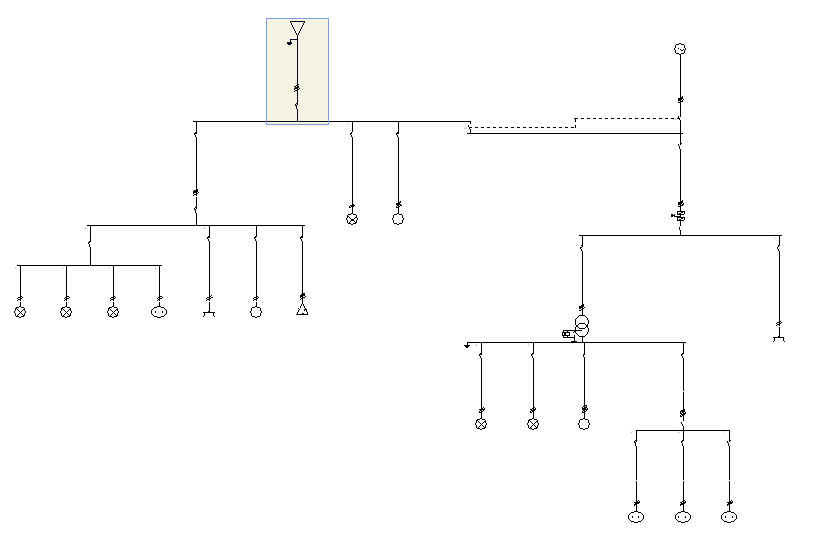
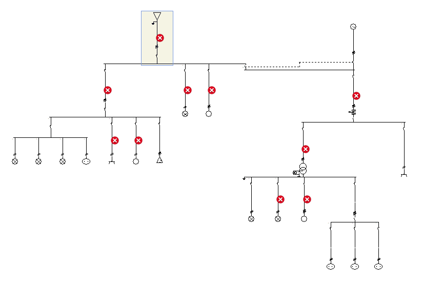
The result is a direct display on the single-line diagram of all lines with errors or warnings.
In the left panel, the tree view of the installation is also complemented by visual indications on the lines showing errors and warnings.
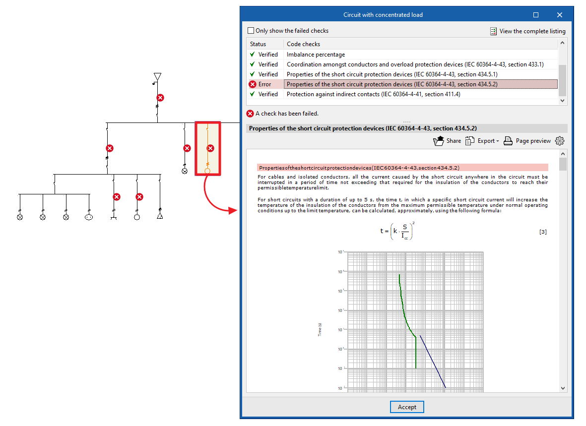
When clicking on a line in the single-line diagram, a window appears showing all the checks that have been carried out for that particular line.
Those checks that are compliant are marked with a green check mark; those that are not compliant are marked with a red cross; and those with a warning are marked with a yellow triangle with an exclamation mark.
By selecting any of the checks that do not comply with the codes, at the bottom of the window it is possible to view the check carried out and the reason for non-compliance with the code.
All checks are justified by the code from which the relevant criteria have been extracted.
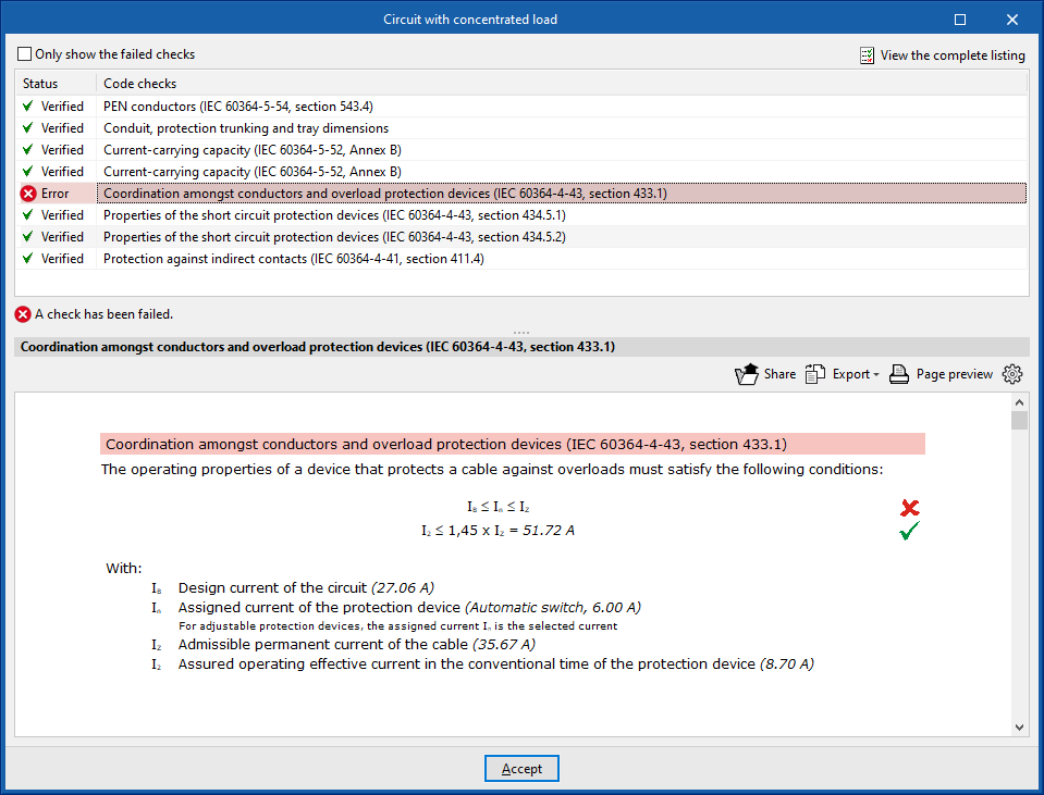
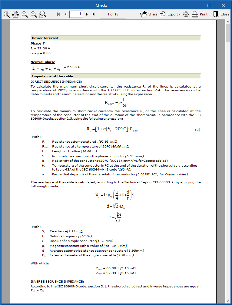
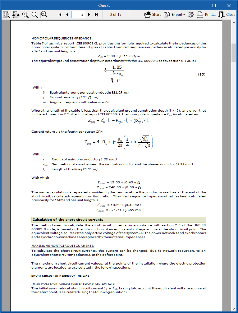
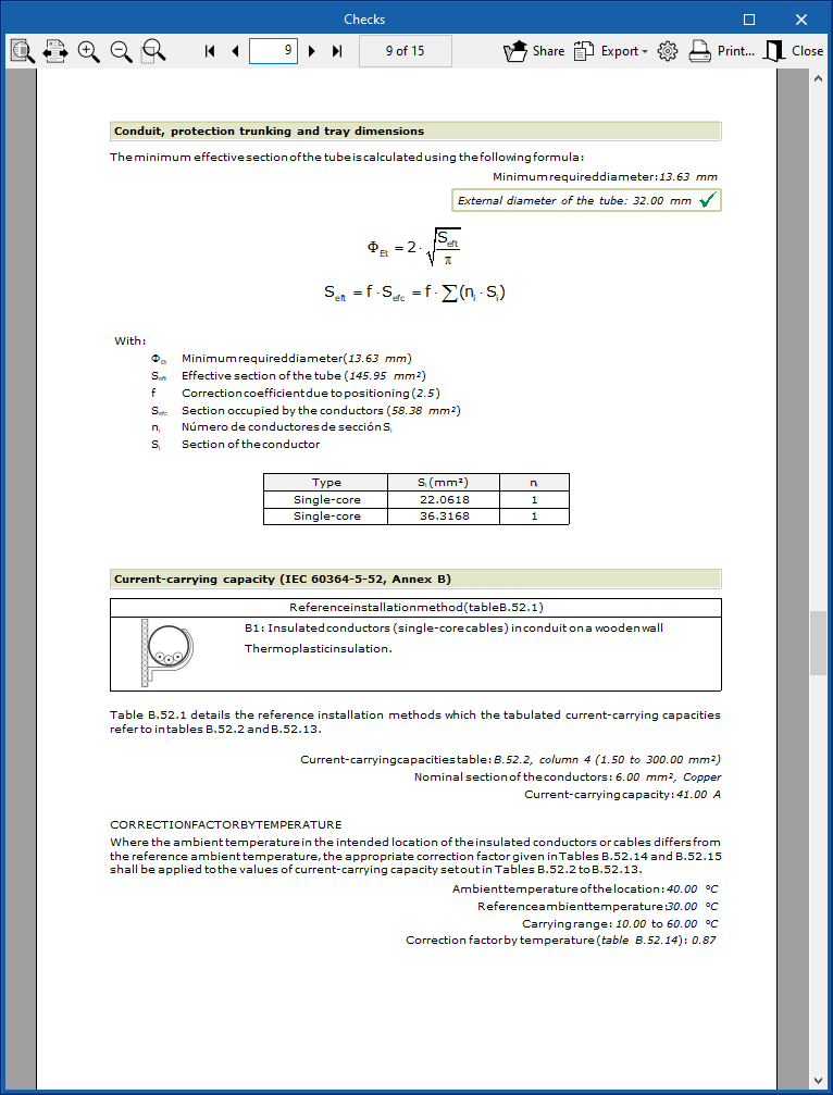
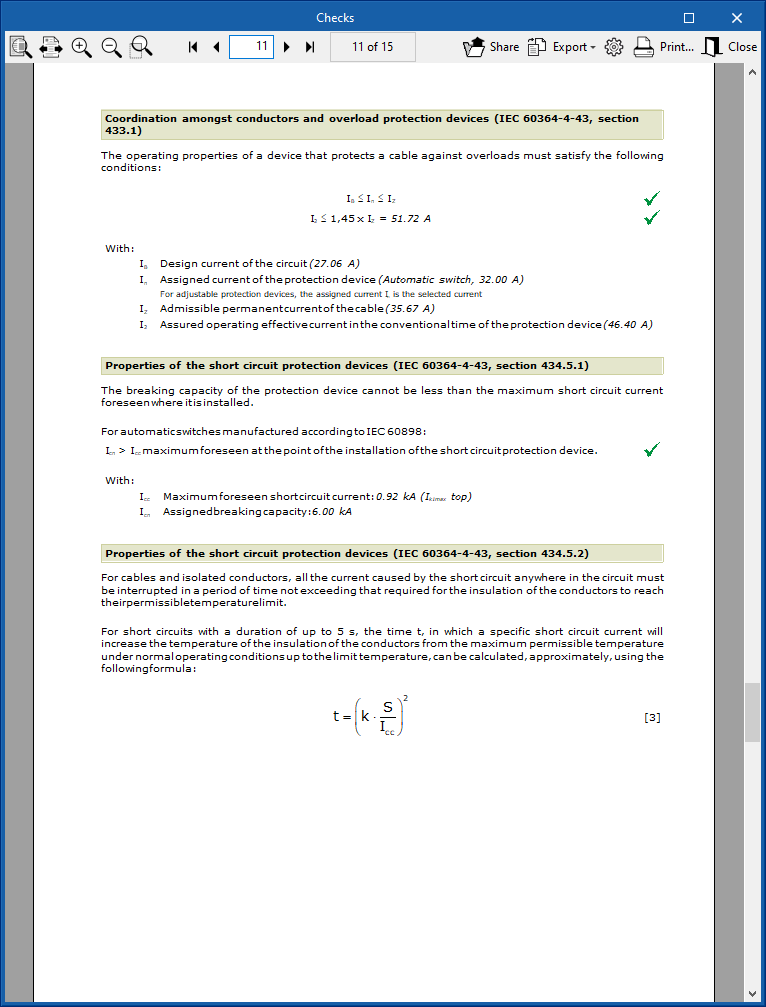
Similarly, when clicking on the "View complete report" option at the top right-hand side of the window, a document appears that lists each one of the analyses and checks that have been carried out during the system's evaluation.
Design
The program also offers the option of carrying out a preliminary design of the installation's lines. To do this, using the current expected to flow through the conductor as a reference, it establishes a section so that the maximum current permitted by this section exceeds the expected current. In the same way, it tries to determine a nominal current of the line's switchgear so that it is higher than the foreseen current but lower than the maximum admissible current for the cable.
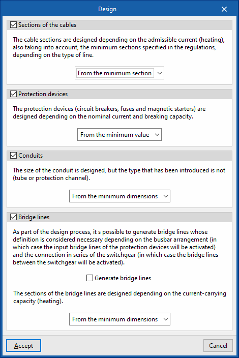
Clicking on the option opens the "Design" window, which allows users to select the following configuration options:
- Sections of the cables (optional)
The sections of the cables are designed according to the admissible current (heating), while also considering the minimum sections specified in the regulations, depending on the type of line. The cable sections can be designed- From the minimum section / As of the selected section
- Protection devices (optional)
The protection devices (circuit breakers, fuses and magnetic starters) are sized by rated current and breaking capacity. Protective devices can be designed:- From the minimum value / From the selected value
- Conduits (optional)
The size of the conduit is designed, but the type of conduit entered (conduit or protection channel) is not modified. The design algorithm allows these dimensions to be established automatically according to the number of contained conductors and the installation conditions. Conduits can be designed:- From the minimum dimensions / As of the selected dimensions
- Bridge lines (optional)
As part of the design process, bridge lines can be generated, the definition of which is necessary depending on the arrangement of busbars (in which case the input bridge lines to the protection devices will be activated) and the series connection of the switchgear (in which case the bridge lines between switchgear will be activated). To do this, the "Generate bridge lines" option must be checked.
The sections of the bridge lines are designed based on the ampacity (heating). Bridge lines can be designed:- From the minimum dimensions / As of the selected dimensions
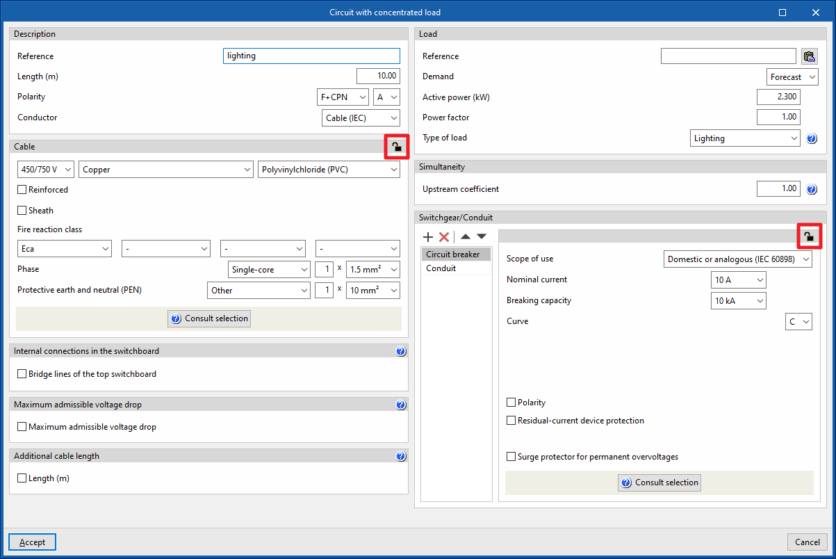
When users don't want the design to change the characteristics entered on a particular line or the characteristics of the protection elements of that line, the possibility to lock the design of that line or that element is provided.
To do this, the desired line is selected and the design is locked by pressing the padlock icon in the top right-hand corner of the corresponding box (it can be unlocked [open padlock] or locked [closed padlock]).
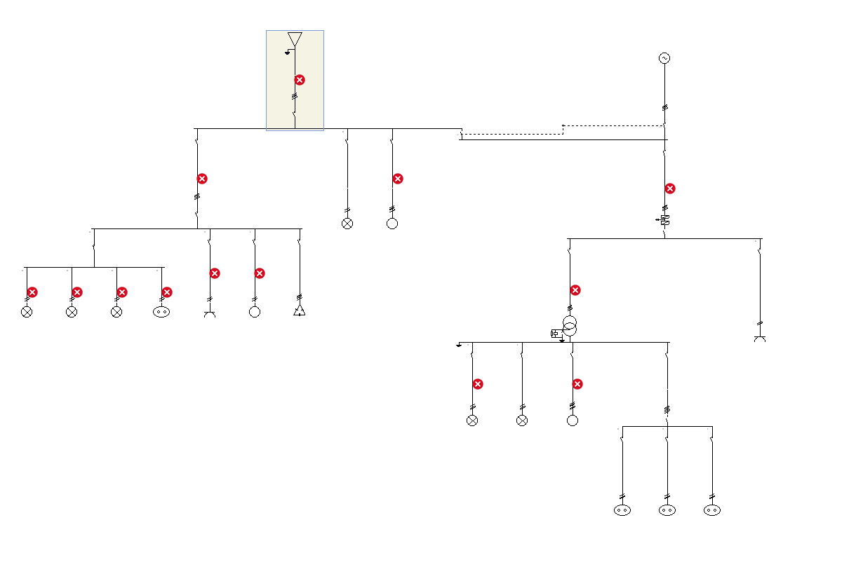
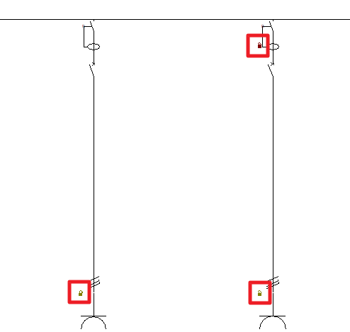
When this operation is carried out, padlock icons may appear on the single-line diagram next to each span of the circuit.
The icon can be red ![]() (indicating that the user has locked the design of an element of the switchgear or the design of the line routing), or green
(indicating that the user has locked the design of an element of the switchgear or the design of the line routing), or green ![]() (indicating that the user has locked the design of the cable section of that span).
(indicating that the user has locked the design of the cable section of that span).
Consult the checks carried out
Allows users to consult the checks made in the last analysis carried out in the job. After selecting the option, users can click on each of the lines to access a window for consulting the checks carried out on them.
As this action does not analyse or update the results, it speeds up the checking and modification of parameters.
If any modifications have been made to the elements in the system, the "Analysis" option must be used for the program to update the displayed results.
Show/Hide incidents
Activating or deactivating this option will highlight or hide marks in the tree and in the single-line diagram on the elements in which an error or warning has occurred in the last analysis. Hovering the mouse cursor over these marks displays a message indicating the existence of issues.