Entering pipes (water distribution)
Within the "Installation" tab, in the "Water distribution" group of the main toolbar, the following options are available to enter the pipes of the system:

Water pipe
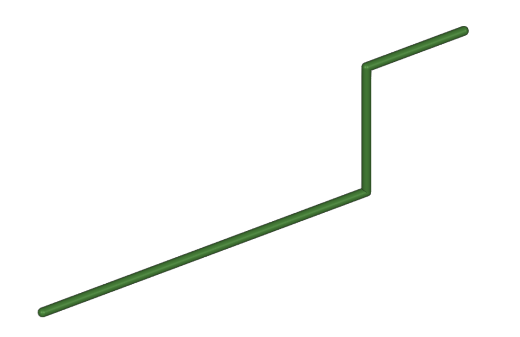
Water pipes can be entered in any direction by drawing them freely in any view of the model.
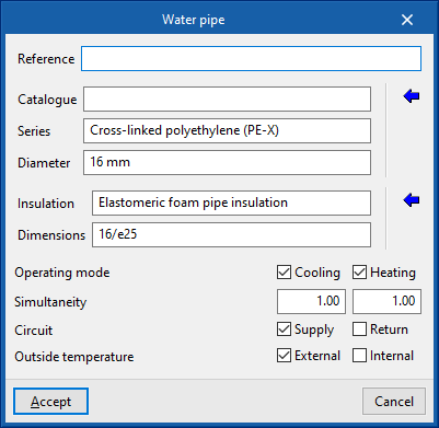
When entering a pipe, the following parameters must be specified:
- Reference
- Pipe selection
- The program selects and imports data from "Manufacturer catalogues" or from the "Library of generic elements" using the wizard on the right-hand side.
- Catalogue
- Series
- Diameter
- Selection of pipe insulation
- The program selects and imports data from the "Library of generic elements" using the wizard on the right.
- Insulation
- Dimensions
- Design conditions
- Operating mode (Cooling (optional); Heating (optional))
- Simultaneity (Cooling; Heating)
- Circuit (Supply (optional) / Return (optional))
- Outside temperature (Outdoor (optional) / Indoor (optional))
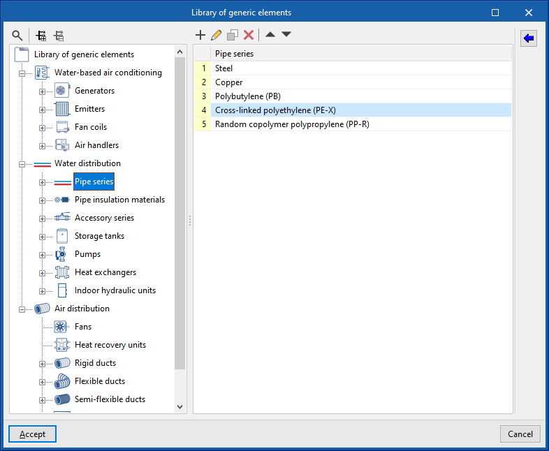
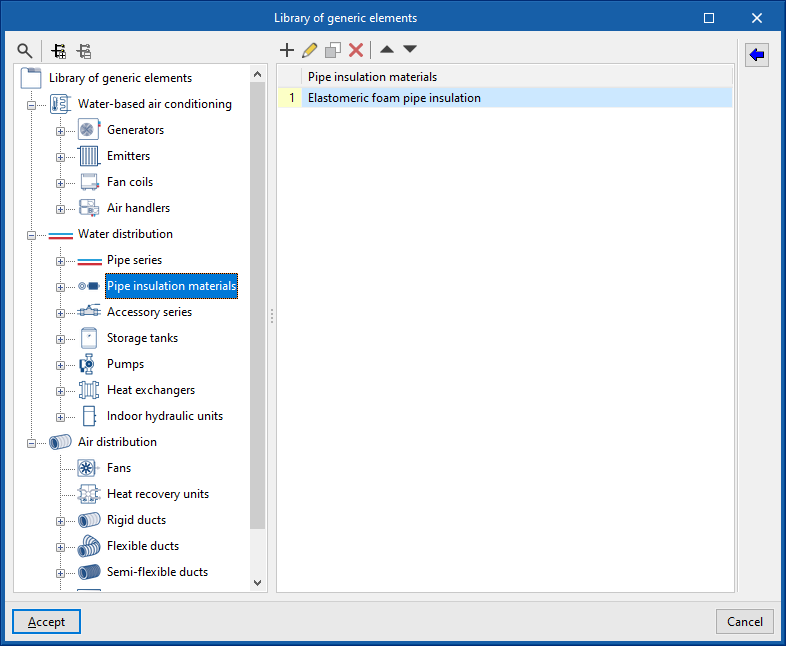
In the "Library of generic elements" option, within the "Project" group, the available generic pipe and insulation libraries can be created and edited.
Pipe library
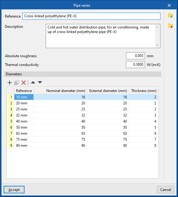
The data associated with each type of pipe is as follows:
- Reference
- Description
- Material
- Absolute roughness
- Thermal conductivity
- Diameters (Reference; Nominal diameter; External diameter; Thickness)
Insulation library
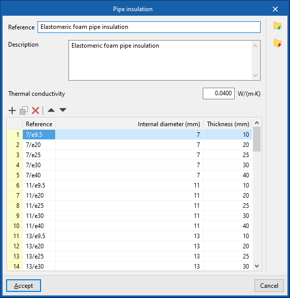
The data associated with each type of insulation is as follows:
- Reference
- Description
- Material
- Thermal conductivity
- Diameters (Reference; Internal diameter; Thickness)
Vertical pipe
Inserts vertical pipes using the elevation of the plan views of the model as a support.
By clicking on this option, the program defines the characteristics of the pipe by means of an editing panel identical to the one that appears when using the "Pipe" option.
Then, in the "Properties - Vertical pipe" dialogue box, the level associated with the "End point" of the pipe is defined, together with a "Displacement" above the indicated level, expressed in positive or negative values. The starting point of the pipe is marked with the cursor on a point in the work area.
The pipe is then laid out from the working plane elevation of the active view, where the starting point has been marked, to the elevation defined by the selected level and the offset indicated in the dialogue box.

Pipe based on the existing pipe
This option inserts new pipes by taking the data from an existing pipe in the model.
To do this, first select the pipe from which the information will be extracted and accept the editing panel. The new pipe is then inserted into the model at the desired position.

