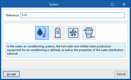
Water-air conditioning systems
Water-based air-conditioning systems include units such as boilers, chillers and air-source heat pump units, as well as the hot or cold water distribution network. Terminal units that may be connected to these systems include radiators, radiant floor heating and fan coils.
Chilled-water system
The definition of chilled-water systems is presented in two sections: "Cold water production equipment" and "Cold water distribution".
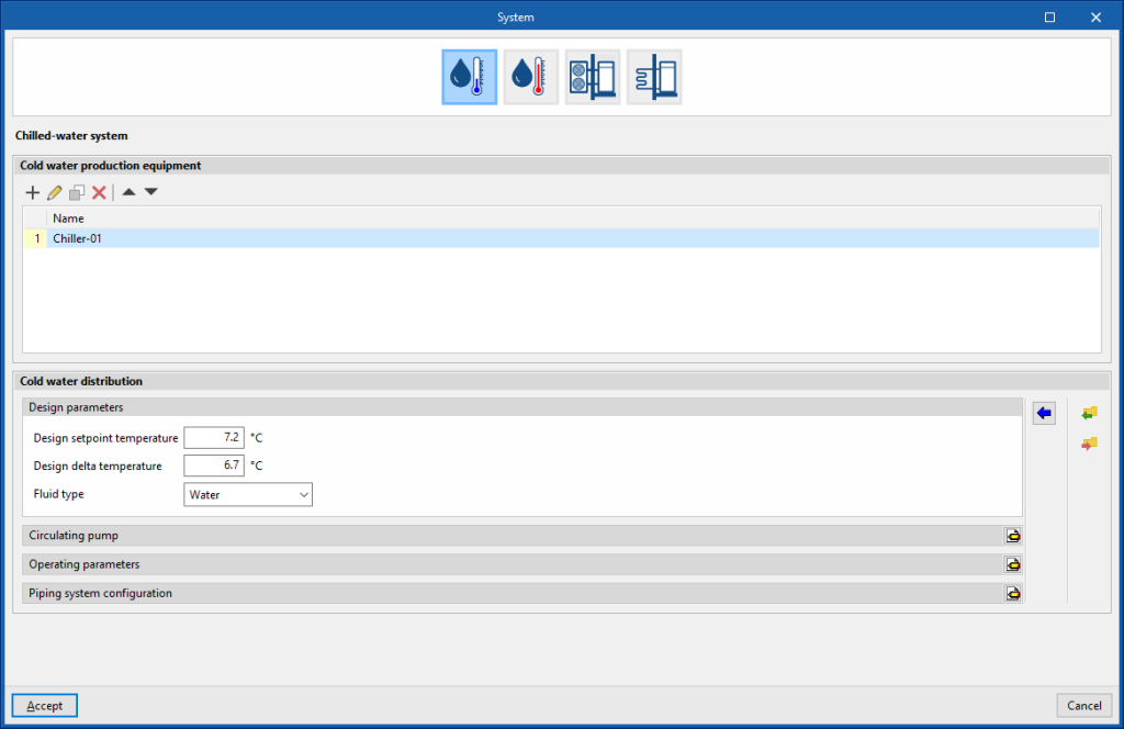
Cold water production equipment (chillers)
This section defines the cold water production equipment (chillers) connected in parallel to the cold water distribution network. A maximum of 10 units can be used.
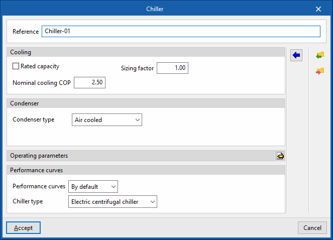
- Reference
Reference of the unit. - Cooling
- Gross rated capacity (optional)
- Sizing factor
If the users do not define a power value, the power of the unit will be determined from the heat load of the zone multiplied by this factor.
- Sizing factor
- Nominal cooling COP
- Gross rated capacity (optional)
- Condenser
- Condenser type (Air cooled / Water cooled / Evaporatively cooled)
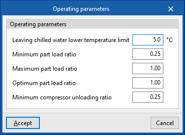
- Operating parameters
- Leaving chilled water lower temperature limit
- Minimum part load ratio
This is the ratio between the minimum power and the gross rated capacity of the unit. Below this load value, the unit operates by switching on and off. - Maximum part load ratio
This is the ratio between the minimum power and the gross rated capacity of the unit. If it is greater than 1, the unit can cover loads above its gross rated capacity. - Optimum part load ratio
This is the ratio between the power that the unit can develop and the gross rated capacity that ensures a higher efficiency. This data only applies if there is more than one unit and, in the "Operating parameters", the loads are to be distributed taking into account this optimum ratio. - Minimum compressor unloading ratio
- Performance curves
- Default
- Electric centrifugal chiller / Electric screw chiller / Electric reciprocating chiller
- User-defined
- Default
Cold water distribution
This section defines the design and operating parameters of the cold water distribution network as well as the circulation pump.
- Design parameters
These parameters are used to automatically calculate the flow rate of the cold water circuit.- Design setpoint temperature
- Design delta temperature
- Type of fluid (Water / Ethylene glycol / Propylene glycol)
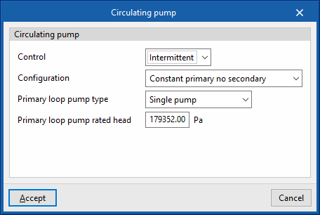
- Circulating pump
- Control (Intermittent / Continuous)
- Intermittent
If the control is intermittent, the pump is switched on and off at the same time as the system. - Continuous
If the control is continuous, the pump is always on, even if there is no demand. In long periods of no demand, heat losses from the pump accumulate in the fluid, which can cause a significant rise in its temperature.
- Intermittent
- Configuration (Constant primary no secondary / Variable primary no secondary / Constant primary variable secondary)
- Primary loop pump type (Single pump / Pump per chiller / Two headered pumps / Three headered pumps / Four headered pumps / Five headered pumps)
- Primary loop pump rated head
- Control (Intermittent / Continuous)
- Operating parameters
- Minimum outdoor temperature
Below this temperature value, the production units do not switch on even if there is demand in the zones. - Load distribution scheme (Optimal / Sequential load / Uniform load / Uniform PLR / Sequential uniform PLR)
This allows users to control the activation of the production units.- Optimal
The units share the load sequentially until the optimum partial load ratio (PLR) indicated for each generator is reached. - Sequential load
The devices are switched on successively, in the order listed, until the load has expired. - Uniform load
The units share the load equally. - Uniform PLR
The units share the load proportionally to their gross rated capacity. - Sequential uniform PLR
This determines how many devices are needed to overcome the load, and the load is distributed among them in proportion to their gross rated capacity. The rest of the units remain switched off.
- Optimal
- Setpoint temperature control (Design setpoint temperature / Outdoor air temperature reset)
During the simulation, the setpoint temperature indicated in this section shall be used.
- Minimum outdoor temperature
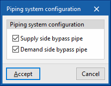
- Piping system configuration
The bypass pipes are used to regulate the power of the circuit in the simulation. They function as valves in a real installation. These options should not be deactivated.- Supply side bypass pipe (optional)
- Demand side bypass pipe (optional)


Hot-water system
There are two sections in the definition of water heating systems: "Hot water production equipment" and "Hot water distribution".
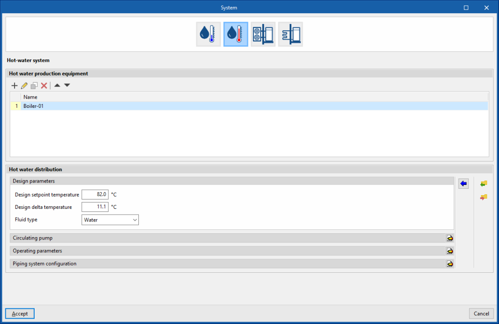
Hot water production equipment
This section defines the hot water production units connected in parallel to the hot water distribution network. A maximum of 10 units can be provided.
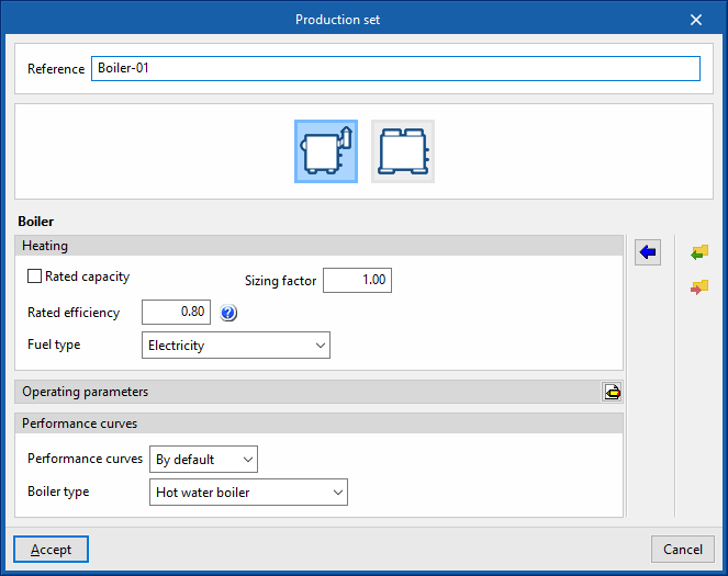
Boiler
- Reference
Reference of the unit. - Heating
- Gross rated capacity (optional)
Allows users to specify a value for the gross rated capacity of the boiler.- Sizing factor
If no power value has been defined, the power of the equipment shall be determined from the heat load of the zone multiplied by this factor.
- Sizing factor
- Rated efficiency
If the performance curve is not defined, the efficiency value of the boiler measured at the following nominal conditions must be given:- Conventional boiler: water outlet at 82°C / Condensing boiler: water inlet at 70°C.
- Fuel type (Electricity / Natural gas / LPG / Diesel / Coal / Biomass / Densified biomass (pellets))
- Gross rated capacity (optional)
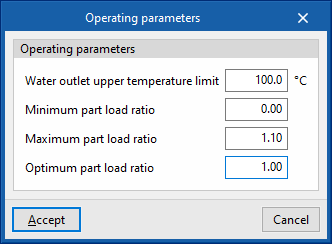
- Operating parameters
- Water outlet upper temperature limit
- Minimum part load ratio
This is the ratio between the minimum power and the gross rated capacity of the unit. Below this load value, the unit operates by switching on and off. - Maximum part load ratio
This is the ratio between the minimum power and the gross rated capacity of the unit. If it is greater than 1, the unit can cover loads above its gross rated capacity. - Optimum part load ratio
This is the ratio between the power that the unit can develop and the gross rated capacity that ensures a higher efficiency. This data only applies if there is more than one unit and, in the "Operating parameters", the loads are to be distributed taking into account this optimum ratio.
- Performance curves
- Default
- Conventional boiler / Condensing boiler
- User-defined
- Default
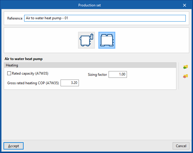
Air to water heat pump
- Reference
Reference of the unit. - Heating
- Gross rated capacity (A7W35) (optional)
Allows users to specify a value for the gross rated capacity of the air-to-water heat pump.- Sizing factor
If no power value has been defined, the power of the equipment shall be determined from the heat load of the zone multiplied by this factor.
- Sizing factor
- Gross rated heating COP (A7W35)
- Gross rated capacity (A7W35) (optional)
Hot water distribution
This section defines the design and operating parameters of the hot water distribution network as well as the circulating pump.
- Design parameters
These parameters are used to automatically calculate the flow rate of the hot water circuit.- Design setpoint temperature
- Design delta temperature
- Type of fluid (Water / Ethylene glycol / Propylene glycol)
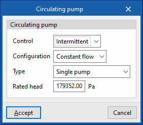
- Circulating pump
- Control (Intermittent / Continuous)
- Intermittent
If the control is intermittent, the pump is switched on and off at the same time as the system. - Continuous
If the control is continuous, the pump is always on, even if there is no demand. In long periods of no demand, heat losses from the pump accumulate in the fluid, which can cause a significant rise in its temperature.
- Intermittent
- Configuration (Variable flow / Constant flow)
- Primary loop pump type (Single pump / Pump per chiller / Two headered pumps / Three headered pumps / Four headered pumps / Five headered pumps)
- Rated head
- Control (Intermittent / Continuous)
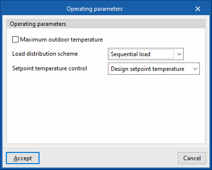
- Operating parameters
- Maximum outdoor temperature
Above this temperature value, the production units do not switch on even if there is demand in the zones. - Load distribution scheme (Optimal / Sequential load / Uniform load / Uniform PLR / Sequential uniform PLR)
This allows the activation of production equipment to be controlled.- Optimal
The units share the load sequentially until the optimum partial load ratio (PLR) indicated for each generator is reached. - Sequential load
The devices are switched on successively, in the order listed, until the load has expired. - Uniform load
The units share the load equally. - Uniform PLR
The units share the load proportionally to their gross rated capacity. - Sequential uniform PLR
This determines how many devices are needed to overcome the load, and the load is distributed among them in proportion to their gross rated capacity. The rest of the units remain switched off.
- Optimal
- Setpoint temperature control (Design setpoint temperature / Outdoor air temperature reset)
During the simulation, the setpoint temperature indicated in this section shall be used.
- Maximum outdoor temperature
- Piping system configuration
The bypass pipes are used to regulate the power of the circuit in the simulation. They function as valves in a real installation. These options should not be deactivated.- Supply side bypass pipe (optional)
- Demand side bypass pipe (optional)
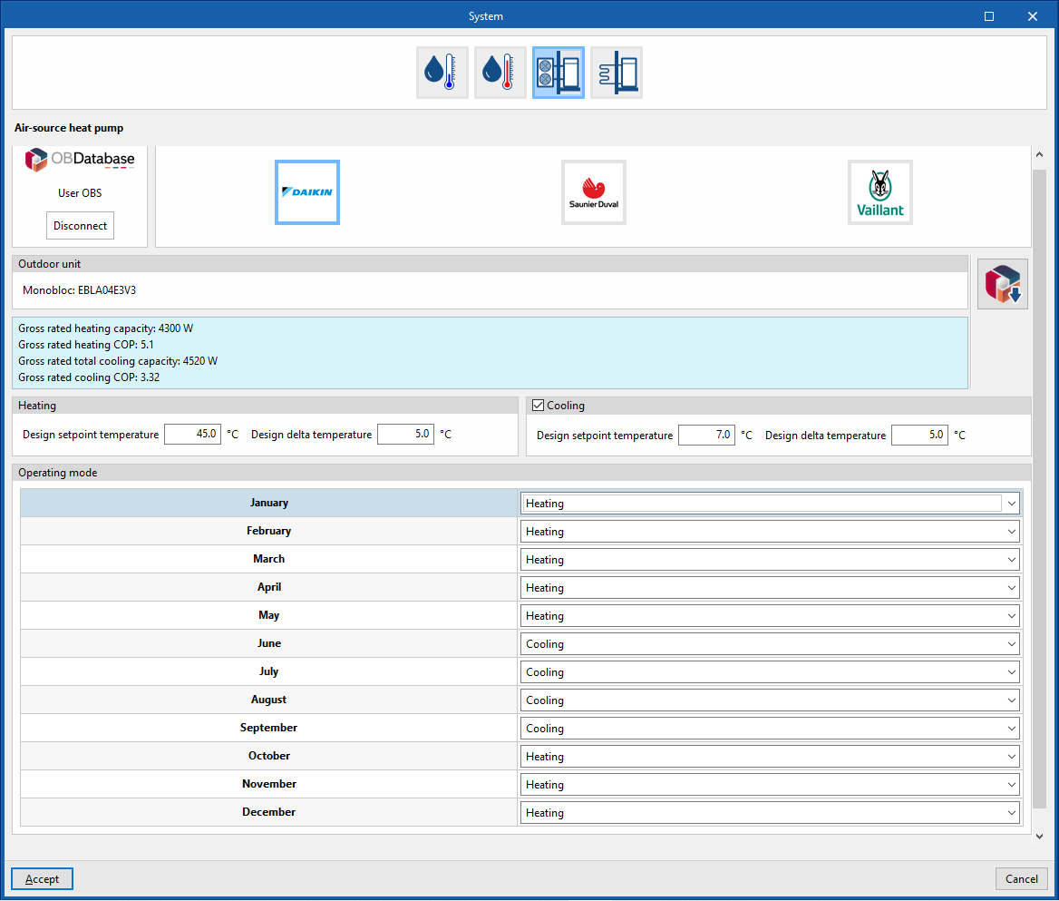
Air-source heat pump system
Manufacturer
Aerothermal
- Open BIM Database unit selection
Allows users to select an aerothermal system from the manufacturers and models available in the Open BIM Database.
Heating
These parameters are used to automatically calculate the flow rate of the water circuit.
- Design setpoint temperature
- Design delta temperature
Cooling (optional depending on the model)
These parameters are used to automatically calculate the flow rate of the water circuit.
- Design setpoint temperature
- Design delta temperature
Operating mode (monthly)
- Heating / Cooling (optional) / Off
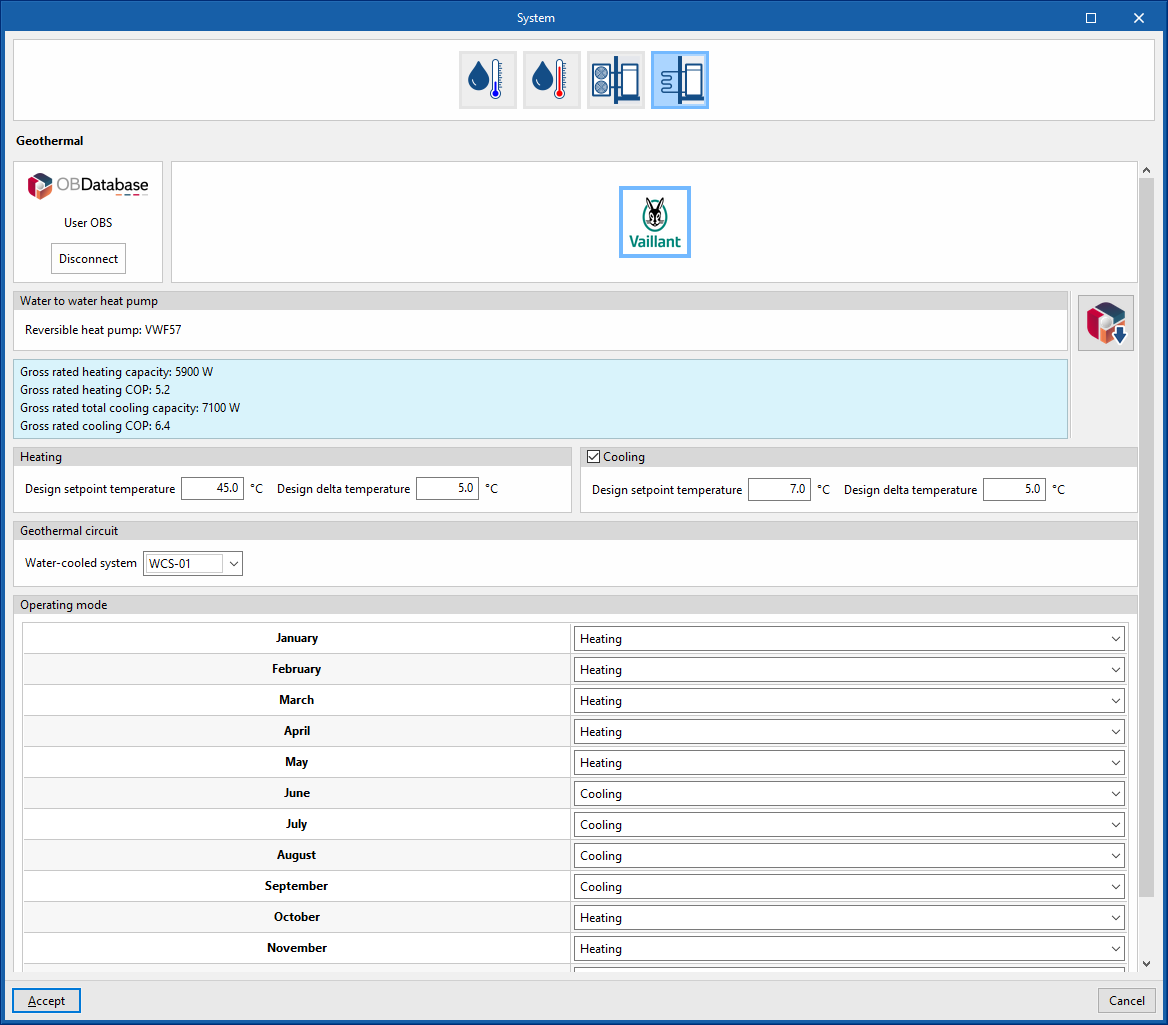
Geometric heat pump
Manufacturer
Geothermal
- Open BIM Database equipment selection
Allows users to select a geothermal heat pump from the manufacturers and models available in the Open BIM Database.
Heating
These parameters are used to automatically calculate the flow rate of the water circuit.
- Design setpoint temperature
- Design setpoint temperature
Cooling (optional depending on model)
These parameters are used to automatically calculate the flow rate of the water circuit.
- Design setpoint temperature
- Design setpoint temperature
Geothermal circuit
Allows users to select a water condensation system at a defined temperature entered in the "Air conditioning systems" section.
- Water-cooled system
Operating mode (monthly)
- Heating / Cooling (optional) / Off