Introduction
Open BIM Cable Routing is a BIM modelling program designed for the distribution of cable routing systems. This tool incorporates the technical information of cables from different manufacturers, for both electrical and telecommunications cables. It can also read the information from the single-line diagram of the electrical system designed in programs such as CYPELEC.

Workflows supported by the program
As an Open BIM tool connected to the BIMserver.center platform, Open BIM Cable Routing offers different workflow options.
Data entry
- Importing models designed in CYPE Architecture.
- Importing models in IFC format.
- Importing models designed in IFC Builder.
- Importing models designed in Autodesk Revit with the Open BIM - Revit Plugin.
- Importing the single-line diagram of the electrical system designed in programs such as CYPELEC.
Data output
- Exporting reports with the material schedule in HTML, DOCX, PDF, RTF or TXT format.
- Exporting drawings to DXF, DWG and PDF formats, among others.
- Exporting IFC and glTF files with the 3D model of the project to the BIMserver.center platform.
- Exporting the bill of quantities in FIEBDC-3 format (.bc3) to use it in quantity surveying programs such as Arquimedes.

Work environment
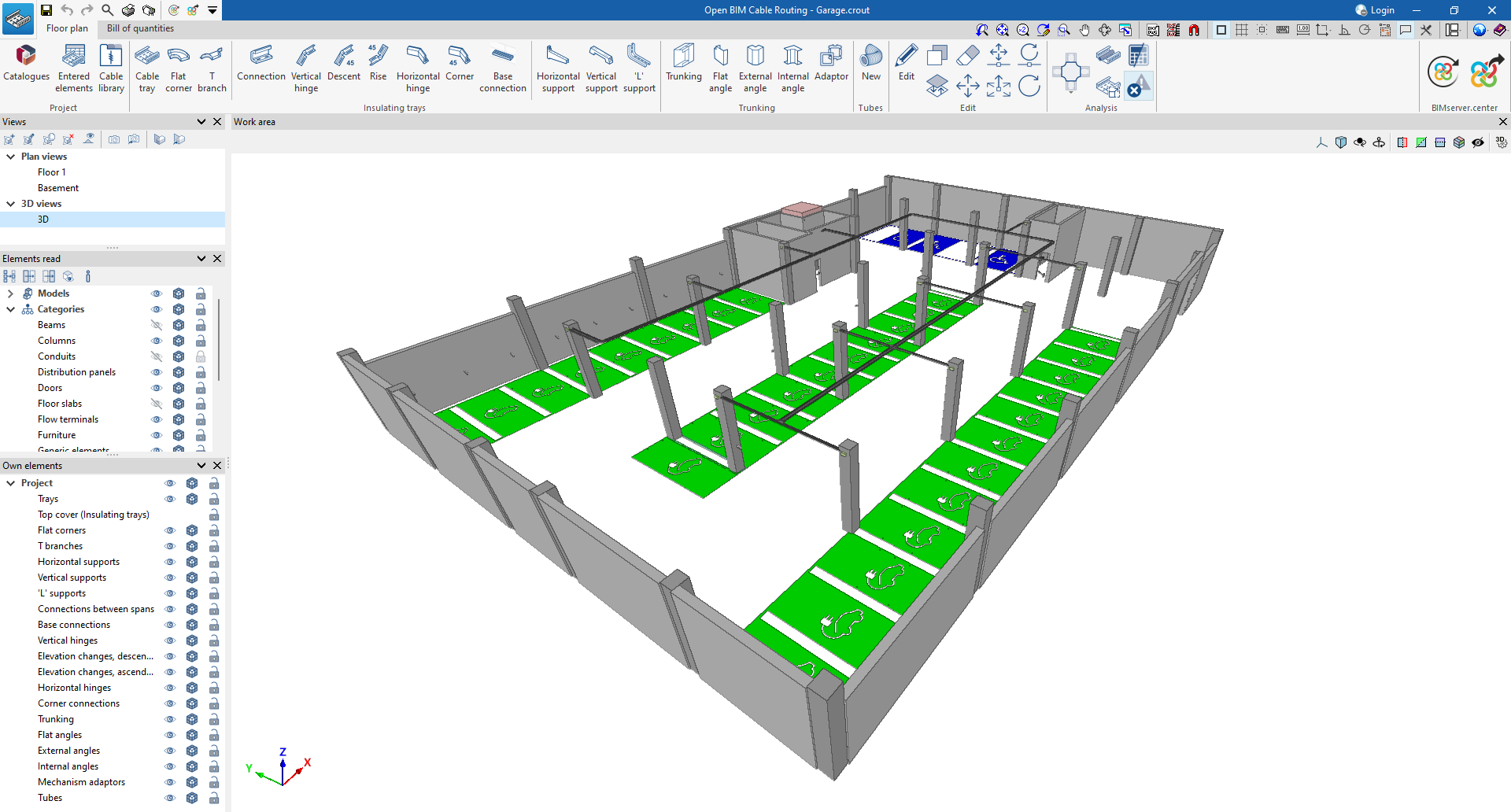
The Open BIM Cable Routing work environment contains two tabs with different work environments: “Floor plan” and “Bill of quantities”.
The default tab activated when launching the program is the "Floor plan" tab. This displays the following:
- At the top are all the tools needed to complete the project, divided into groups related to the project, conduit systems (insulating trays, trunking and conduits), editing and design.
- On the left-hand side are the views of the model, the elements read and the own elements. These can be moved and resized, be floated, pinned to a location within the main application dialogue box, dragged out of the main application dialogue box, and even moved to another screen.
- The modelling area is located in the middle right-hand side of the start screen and is used to enter, edit and view all project elements in 3D.
On the other hand, the "Bill of quantities" tab also shows:
- A top toolbar containing tools for creating and editing the bill of quantities, as well as tools for managing and creating reports.
- A graphic window with its own toolbar, located on the right-hand side, where the conduit systems incorporated in the project can be viewed.
- A specific area for structuring the bill of quantities, on the left-hand side.
Creating a new job and linking it to a project
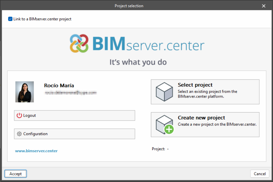
When launching the application and clicking on "New", users are given the option of creating a "New job", which can then be integrated into an existing project in BIMserver.center.
There is also the option to "Create new project". In this case, the created project will be visible from BIMserver.center from that moment on.
Once the new job has been created, users then access the interface, in which the graphic window showing the model or models that have been imported is displayed.
Users also have the option of starting the project without being linked to the BIMserver.center platform. To do this, simply uncheck the "Link to a BIMserver.center project" box in the top left-hand corner.
Files can be shared or imported at any time while the project is in progress via the BIMserver.center tab located at the top right of every program.
Importing BIM models
When creating a new job and selecting a project hosted on the BIMserver.center platform via "Select project", the "Import of BIM models" window appears, which shows the files contained in the project in IFC format.
The application offers users the option of including one or more of the existing models in the project. To do this, check the "Import" box and accept it.
When accessing the interface, the graphical window will display the imported models.

Defining the project characteristics

In the "Floor plan" tab, in the "Project" group of the main toolbar, the following project data can be defined:
Catalogues
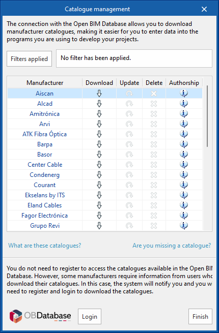
Open BIM Cable Routing allows users to select catalogues of trays, conduits, tubes and cables from leading manufacturers.
The available options include "Download", "Update" or "Delete" for each manufacturer's catalogue. Users can also log in to the Open BIM Database to download other catalogues available on the Open BIM Database platform.
Entered elements
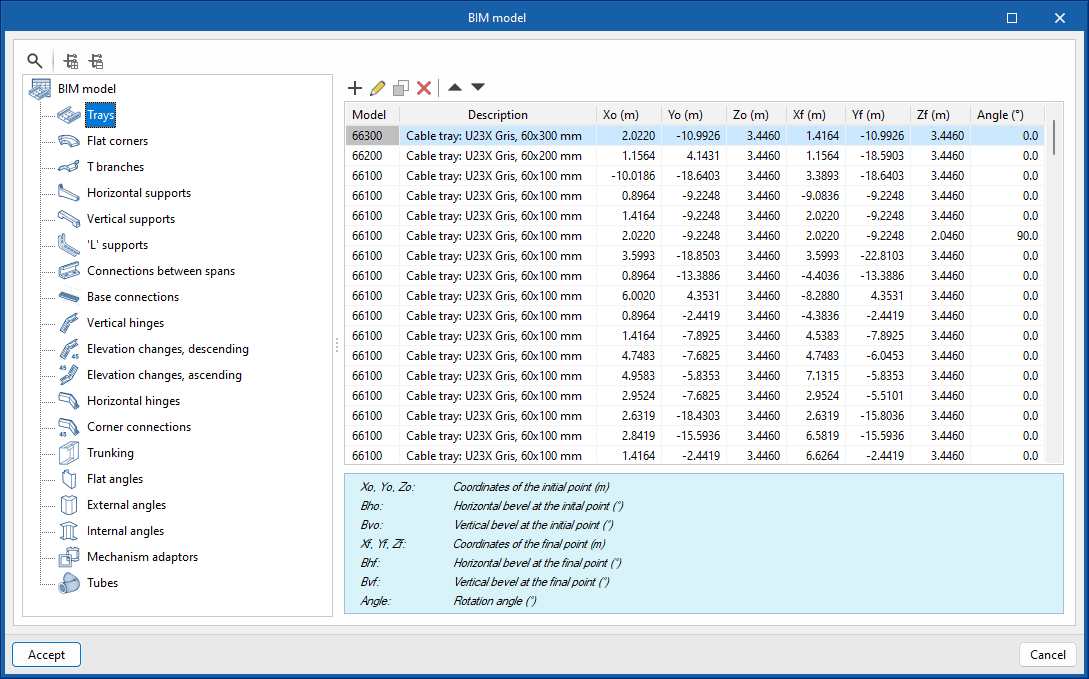
This allows users to consult and modify the data of the elements entered in the model through a series of tables that contain the following information:
- Trays: model, description, Xo, Yo, Zo, Xf, Yf, Zf, angle.
- Flat corners: model, description, X, Y, Z, Ux, Uy, Uz, Vx, Vy, Vz.
- T branches: model, description, X, Y, Z, Ux, Uy, Uz, Vx, Vy, Vz.
- Horizontal supports: model, description, X, Y, Z, Ux, Uy, Uz, Vx, Vy, Vz.
- Vertical supports: model, description, X, Y, Z, Ux, Uy, Uz, Vx, Vy, Vz.
- 'L' supports: model, description, X, Y, Z, Ux, Uy, Uz, Vx, Vy, Vz.
- Connections between spans: model, description, X, Y, Z, Ux, Uy, Uz, Vx, Vy, Vz, angle obtained due to bending of the element.
- Base connections: model, description, X, Y, Z, Ux, Uy, Uz, Vx, Vy, Vz, angle obtained due to bending of the element.
- Vertical hinges: model, description, X, Y, Z, Ux, Uy, Uz, Vx, Vy, Vz, angle obtained due to bending of the element.
- Elevation changes, descending: model, description, X, Y, Z, Ux, Uy, Uz, Vx, Vy, Vz, angle obtained due to bending of the element.
- Elevation changes, ascending: model, description, X, Y, Z, Ux, Uy, Uz, Vx, Vy, Vz, angle obtained due to bending of the element.
- Horizontal hinges: model, description, X, Y, Z, Ux, Uy, Uz, Vx, Vy, Vz, angle obtained due to bending of the element.
- Corner connections: model, description, X, Y, Z, Ux, Uy, Uz, Vx, Vy, Vz.
- Trunking: model, description, Xo, Yo, Zo, Xf, Yf, Zf, angle.
- Flat angles: model, description, Xo, Yo, Zo, Xf, Yf, Zf, angle.
- External angles: model, description, X, Y, Z, Ux, Uy, Uz, Vx, Vy, Vz.
- Internal angles: model, description, X, Y, Z, Ux, Uy, Uz, Vx, Vy, Vz.
- Mechanism adaptors: model, description, X, Y, Z, Ux, Uy, Uz, Vx, Vy, Vz.
- Tubes: model, description.
Cable library
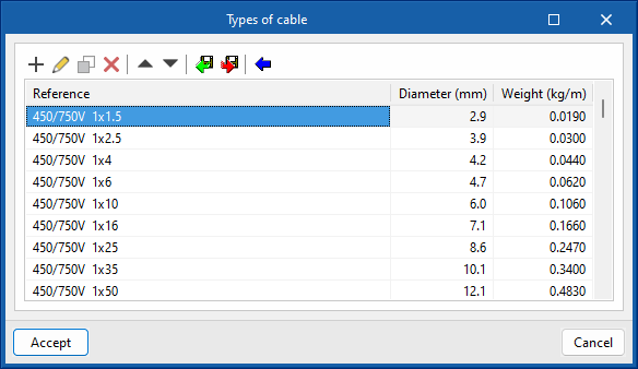
Open BIM Cable Routing allows users to import predefined cable types from the blue arrow, as well as to create new user-defined cable types.
The information collected for each type of cable is the reference, diameter and weight.
Conduit systems

Insulating trays
Within the “Insulation trays” group of the main toolbar, the following elements can be added to the project:
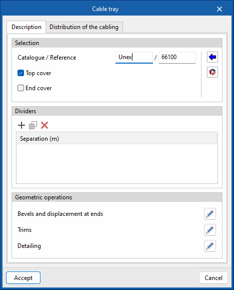
- Cable tray
Users select the manufacturer and type of tray, whether or not it has a top cover and end cover. They can also add compartments, define bevels and/or trims and add wiring. - Flat corner
The manufacturer and type of corner, whether or not it has a cover, are selected. - T branch
The manufacturer and the type of branch, whether or not it has a cover, are selected. - Connection
The manufacturer and the type of connection are selected. - Vertical hinge
The manufacturer and type of hinge are selected. - Descent
The manufacturer and type of elevation change are selected. - Rise
The manufacturer and the type of level change are selected. - Horizontal hinge
The manufacturer and type of hinge are selected. - Corner
The manufacturer and the type of connection are selected. - Base connection
The manufacturer and type of connection are selected. - Horizontal support
The manufacturer and type of support are selected. - Vertical support
The manufacturer and bracket type are selected. - 'L' support
- The manufacturer and bracket type are selected.
Note:
Wiring can be selected in two ways, from the single-line diagram of the project (having previously connected to a BIMserver.center project) or from a manufacturer's catalogue or the library.
Best practice:
The detailing (section and length) will only be available when selecting or editing any element previously entered in the project.
Trunking
In the “Trunking”’ group of the main toolbar, the following elements can be added to the project:
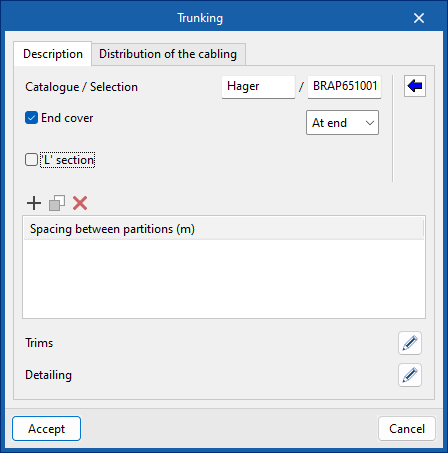
- Trunking
The manufacturer and type of trunking are selected, whether or not the trunking has an end cover and/or ‘L’ section. Users can also add compartments, define trims and add wiring. - Flat angle
The manufacturer and type of angle are selected. - External angle
The manufacturer and type of angle are selected. - Internal angle
The manufacturer and type of angle are selected. - Adaptor
- The manufacturer and type of adaptor are selected.
Tubes
In the “Tubes”’ group of the main toolbar, the following elements can be added to the project:
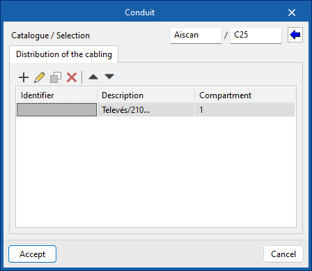
- New
The manufacturer and type of tube is selected, and wiring is selected if desired.
Automatic generation tools

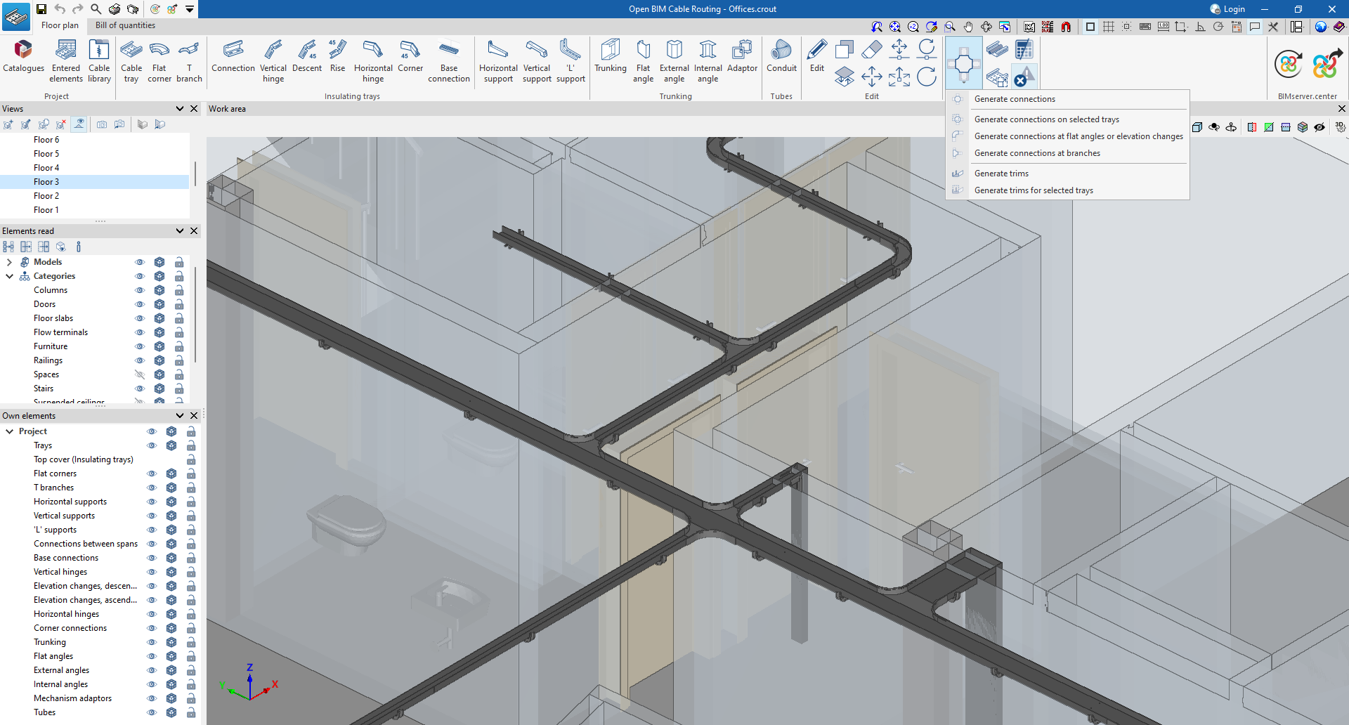
In the “Floor plan” tab, in the “Generate” group of the main toolbar, there are options for automatically generating connections and trims, as well as for showing or hiding the detected issues. The following options are available:
- Generate connections
- Automatically allows users to make bevels and include hinges or flat corners in flat angles and elevation changes, without selecting any elements. Also, in branches, they can carry trims and bevels and include hinges or T-branches.
- Generate connections on selected trays
- Allows users to generate connections on the selected trays.
- Generate connections at flat angles or elevation changes
Allows users to generate connections only at the selected angles or elevation changes. - Generate connections at branches
Allows users to generate connections only at selected branches. - Generate trims
Allows users to automatically generate trims at the intersection of two parts on all trays. - Generate trims for selected trays
Allows users to trim the selected trays. - Generate
Automatically generates the electrical cables that run along the conduits. Please note that this can only be carried out if the conduit route coincides with one of the conduits read from the project it is connected to from BIMserver.center. - Design
Automatically designs the conduits based on their vertical section, ensuring that it is sufficient for the sections of the cables it contains. - Consult checks
Checks the capacity of the cables within the selected conduit, provided that the conduit contains cables. The tool shows the total occupied section, the total available section and the percentage of occupation. - Show/hide incidents
- When this option is activated, the elements in which an error has occurred are highlighted. If the cursor is positioned over these elements, the message describing the error is displayed.
Editing tools
In the "Floor plan" tab, in the "Edit" group of the main toolbar, users will find the main tools for editing the model. Some of these tools are common to other CYPE programs.

 | Edit | Edits the parametric properties of the selected element in the model. |
| Copy | Creates a copy of an element. | |
 | Delete | Deletes a previously entered element. |
 | Move | Moves a single element. |
| Rotate | Rotates an element around an axis defined by two points. | |
| Copy onto another floor plan | Copies the selection to another floor plan. | |
 | Move | Moves a group of elements. |
| Modify height position | Changes the height position of the selection. | |
 | Rotate a group of elements | Rotates a group of elements. |
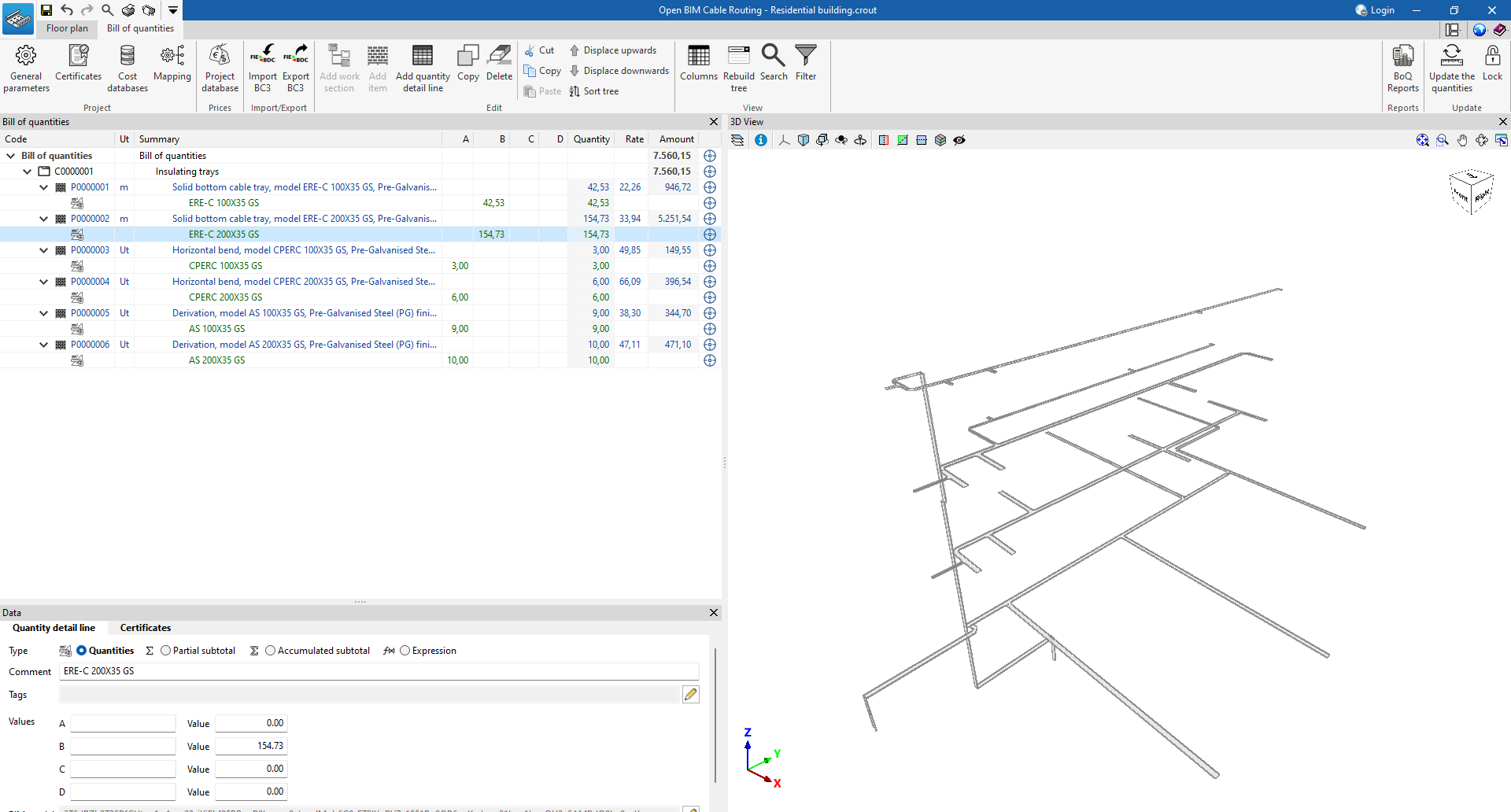
“Bill of quantities” tab

The "Bill of quantities" tab contains tools for generating and managing the bill of quantities.
From this window, users can manage the general parameters, certificates, cost databases, mapping and project databases. There are also options for importing and exporting in BC3, manually editing the bill of quantities, managing its visualisation, generating reports and updating the quantities, among others.
| Más información: |
|---|
| The following link provides detailed information about the "Bill of quantities" tab in Open BIM apps that include it, explaining all the available features in more detail. |
Results output
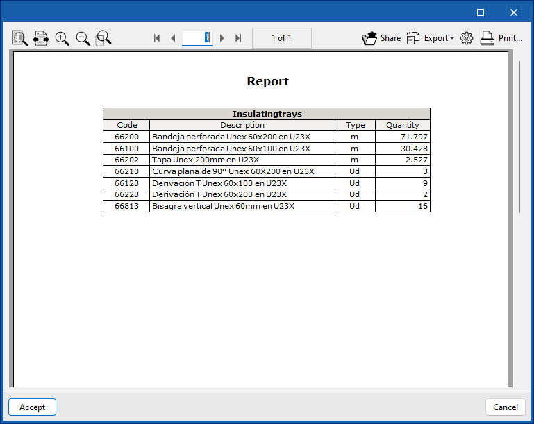
Reports
From the "Reports" option in the top left-hand area of the interface, Open BIM Cable Routing can display the report with the references and description of the cable routing systems entered, including their quantities.
These reports can be printed directly or exported in HTML, PDF, TXT, RTF or DOCX format.
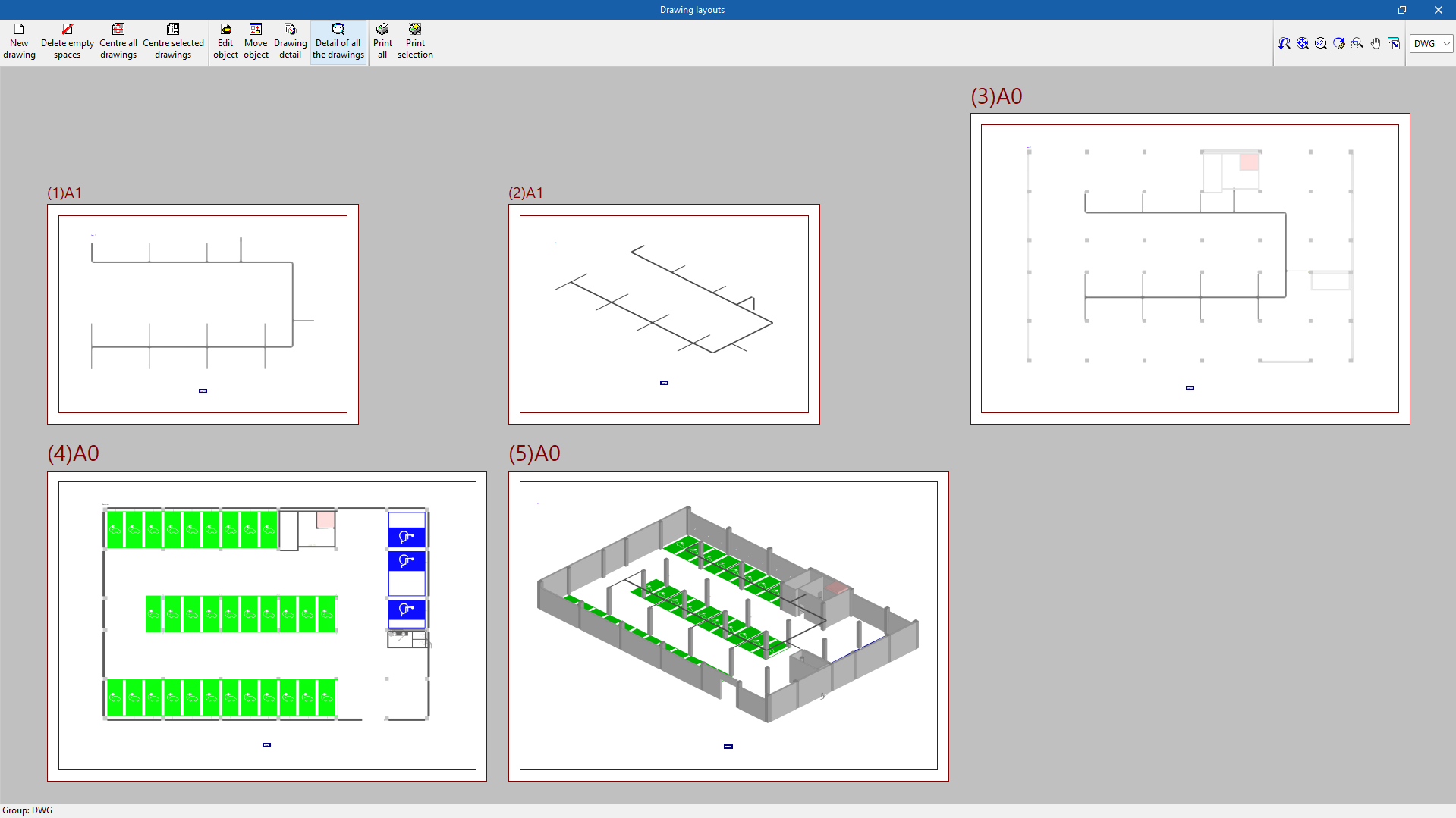
Drawings
Open BIM Cable Routing allows users to generate floor plans or 3D views and export them in DWG, DXF or PDF format, among others.
Drawings can be obtained via the corresponding option at the top left of the program's general interface.
IFC and glTF files, compatible with BIMserver.center
When exporting the project to the BIMserver.center platform, a 3D model in IFC and glTF format will be automatically exported for integrating the structure model into the Open BIM project, allowing:
- viewing the model on the online platform;
- viewing the model in the BIMserver.center application for iOS and Android;
- viewing the model in virtual reality and augmented reality;
- viewing the model in other CYPE tools;
- integrating the model in the project and compatibility with the rest of the project's disciplines with Open BIM Model Checker.
Bill of quantities in FIEBDC-3 format (.bc3)
As well as generating “BoQ Reports”, the bill of quantities can be exported in standard FIEBDC-3 (.bc3) format so that it can be read by any compatible application.
To carry out the export, simply use the “Export BC3” tool in the “Import/Export” group of the “Bill of quantities” tab, assign a name to the file and activate the desired boxes to include associated information (graphic information, attached documents, specifications, technical information, etc.).
Integration into the BIMserver.center platform
Many of CYPE's programs are connected to the BIMserver.center platform and allow collaborative work to be carried out via the exchange of files in formats based on open standards.
Please note that, to work on BIMserver.center, users can register on the platform free of charge and create a profile.
When accessing a program connected to the platform, the program connects to a project in BIMserver.center. This way, the files of the projects that have been developed collaboratively in BIMserver.center are kept up to date.

Options available in Open BIM Cable Routing
In the “Floor plan” tab, in the "BIMserver.center" group of the main toolbar, are the main options for using the model with other BIMserver.center tools.

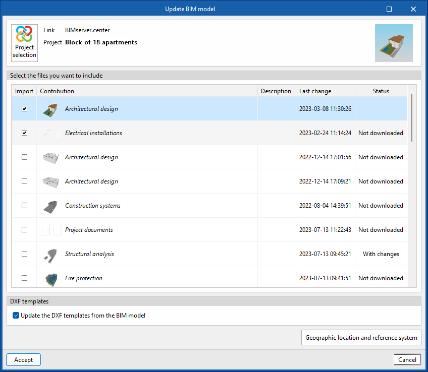
Importing and updating BIM models
The “Update” option allows you to update the information contained in the models previously imported into the project or to import new models if desired.
The import of models is carried out according to the defined configuration and users can choose how new, modified and deleted elements of the BIM model are shared.
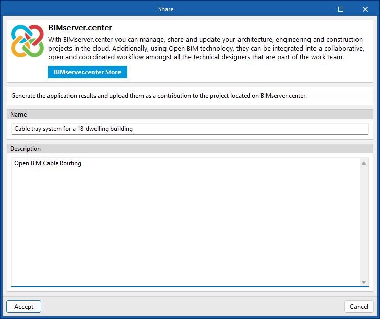
Exporting the BIM model and sharing it with other users
Using the “Share” option, the information contained in the model developed with Open BIM Cable Routing can be exported to BIMserver.center.
During the export process, users can define information related to the identification of the files to be exported.