Setting the analysis and drawing options for the water supply system
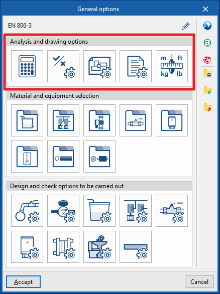
In the "Installation" tab of the "Water Systems" tab, in the "General Options" of the "Project" group in the main toolbar, the "Analysis and drawing options" of the water supply system can be configured:

- Calculation options
- General checks
- Representation options
- Report configuration
- Units
By using the "Import configuration" option, available on the right-hand side of the "General options" panel, this data can be automatically generated for different national and international standards. Similarly, data from different manufacturers can be imported by clicking on the options with their logo.
The other options in the right-hand column are for importing and exporting the complete configuration of the "General options" panel to files on disk, as well as selecting a file with initial values for creating a new job.
Calculation options
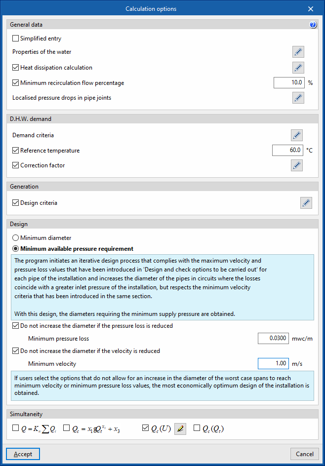
Defines the general data and criteria for the design of the water supply system.
- General data
The formula used in the hydraulic analysis of the system can be consulted using the help button on the right-hand side of this section. The Darcy-Weisbach formula is used to calculate the pressure losses in each section of the network. The expressions that determine the analysis of the hot water return networks are also shown.- Simplified entry (optional)
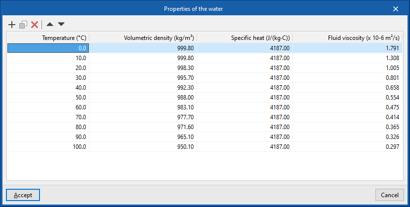
If this option is activated, the panels for entering and editing the elements in the system have a simplified appearance and don't need to be defined by the user. - Properties of the water
This allows the density, specific heat and viscosity of water to be defined for each temperature value. - Heat dissipation calculation (optional)
Activates the heat dissipation calculation. The ambient temperature value must be entered. - Minimum recirculation flow percentage (optional)
Defines a minimum recirculation flow percentage in the hot water return circuits. - Localised pressure drops in pipe joints
Selects the type of local pressure drop to be assigned at the joints of the different kinds of pipes when using the tools for automatically generating "Local pressure drops at pipe joints" available in the "Water supply" group of the main toolbar. The library of pressure loss types can be configured from "Fittings", in the "Design and check options to be carried out" section of the "General options".- Cold water (45° elbow, 90° elbow, Tee, Reducer)
- Hot water (45° elbow, 90° elbow, Tee, Reducer)
- Hot water return (45° elbow, 90° elbow, Tee, Reducer)
- Auxiliary supply (45° elbow, 90° elbow, Tee, Reducer)
- Auxiliary return (45° elbow, 90° elbow, Tee, Reducer)
- Simplified entry (optional)
- D.H.W. demand
- Demand criteria
Defines the available DHW demand criteria, indicating the reference, description and daily demand, per unit (in volume units). This criteria can then be selected to enter the necessary information in the "Consumption" section of the "DHW production" equipment. - Reference temperature (optional)
Defines the reference temperature of the DHW demand. - Correction factor
Defines a correction factor for the DHW demand according to the number of consumers.
- Demand criteria
- Generation
- Design criteria (optional)
Selects the type of pipe that the program assigns to each span of the system during the design, if the "Pipe reference" section is kept unlocked in each pipe entered in the model. The kinds of pipes can be created in "Pipes", in the "Design and check options to be carried out" section of the "General options".- Cold water (Supply connection points, Meter pre-installation, Meter assembly, Shut-off valve, Valve of the room with plumbing, Consumption, Others)
- Hot water (Hot water production, Meter pre-installation, Meter assembly, Shut-off valve, Valve of the room with plumbing, Consumption, Others)
- Design criteria (optional)
- Design
- Minimum diameter
If this option is chosen, the system design is carried out with the maximum values of velocity and pressure loss entered for each pipe from "Pipes", in the "Design and check options to be carried out" section of the "General options". With this design, the minimum possible diameters are obtained, if the supply pressure is sufficient. - Minimum available pressure requirement
If this option is chosen, the program starts an iterative design process which, as well as complying with the maximum values of velocity and head loss introduced for each pipe (in "Piping", in the "Design and check options to be carried out" section of the "General options") increases the diameter of the pipes in the circuits where the losses condition a higher inlet pressure in the system, respecting the minimum velocity criteria entered in the same section. This design obtains the diameters that require the minimum possible supply pressure. Furthermore, if the following options are selected, which do not allow the diameter of the most unfavourable sections to be increased when reaching a minimum speed or a minimum pressure loss, a sizing of the system that is closer to the optimum economic design is obtained:- Do not increase the diameter if the pressure loss is reduced (optional)
- Minimum pressure loss
- Do not increase the diameter if the velocity is reduced (optional)
- Minimum velocity
- Do not increase the diameter if the pressure loss is reduced (optional)
- Minimum diameter
- Simultaneity
Selects and defines the simultaneity analysis methods available in the project. It is then possible to choose one of these methods for each pipe defined in "Pipes", in the "Design and check options to be carried out" section of the "General options".- Q = Kn Σ Qi
Defines the simultaneous flow rate as a function of the sum of the instantaneous flow rates (Qi) and the coefficient (Kn). This coefficient depends on the number n of consumptions and its calculation expression takes different forms, which can be selected for each pipe defined in "Pipes", in the "Design and check options to be carried out" section of the "General options". - Qc = x1 × Qtx2 + x3
Defines the simultaneous or calculation flow rate as a function of the gross flow rate (Qt) and the x1, x2 and x3 parameters, which can be defined by flow rate ranges. This method is proposed in some documents such as the UNE 149201:2017 standard. - Qc (U)
Defines the simultaneous or calculation flow rate (Qc) as a function of the number of consumption units (U). - Qc (Qt)
Defines the simultaneous or calculation flow rate (Qc) as a function of the gross flow rate (Qt).
- Q = Kn Σ Qi
General checks
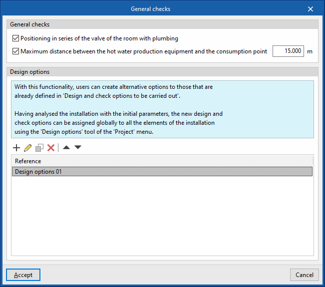
Defines the general checks of the water supply system.
- General checks
- Positioning in series of the valve of the room with plumbing (optional)
- Maximum distance between the hot water production equipment and the consumption point (optional)
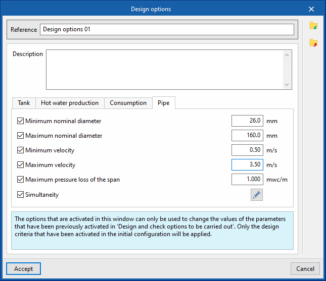
- Design options
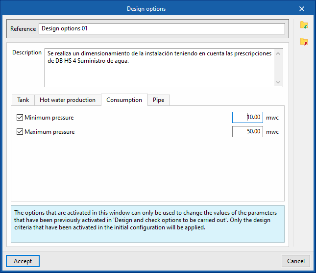
With this feature, users can configure alternative design options globally for all the elements in the system. The parameters activated and entered in this window are only used to change the values of the parameters that are previously activated in each type of element defined in the "General options", from where the "Design and check options to be carried out" are accessed. Furthermore, once defined, these options will not be applied to the design of the system until the user assigns them using the "Design options" option in the "Project" group of the top tool menu in the general interface.- Reference
- Description
- "Deposit" tab
- Minimum pressure (optional)
- Maximum pressure (optional)
- “Hot water production” tab
- Minimum pressure (optional)
- Maximum pressure (optional)
- “Consumption” tab
- Minimum pressure (optional)
- Maximum pressure (optional)
- “Pipe” tab
- Minimum nominal diameter (optional)
- Maximum nominal diameter (optional)
- Minimum velocity (optional)
- Maximum velocity (optional)
- Maximum pressure loss of the span (optional)
- Simultaneity (optional)
Representation options
Configures the graphical representation of the elements in the water supply system.
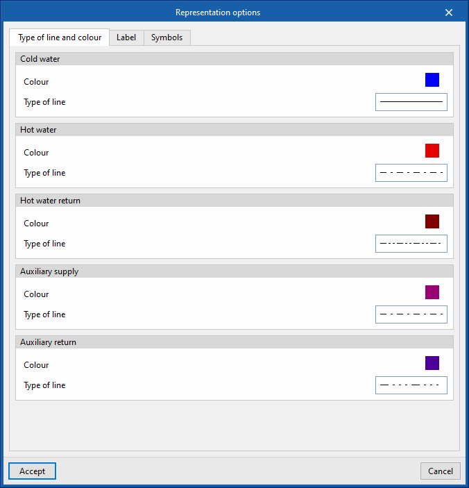
- “Type of line and colour” tab
Modifies the type of line and the colour used in the graphical representation of the different types of pipes.- Cold water (Colour, Type of line)
- Hot water (Colour, Type of line)
- Hot water return (Colour, Type of line)
- Auxiliary supply (Colour, Type of line)
- Auxiliary return (Colour, Type of line)
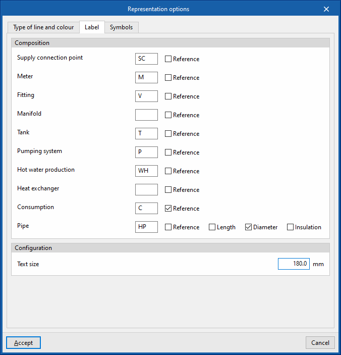
- “Label” tab
Adjusts the information displayed in the labels of the different elements in the water supply system and their text size.- Composition (Supply connection point, Meter, Fitting, Manifold, Tank, Pumping system, Hot water production, Heat exchanger, Consumption, Pipe)
- Configuration
- Text size
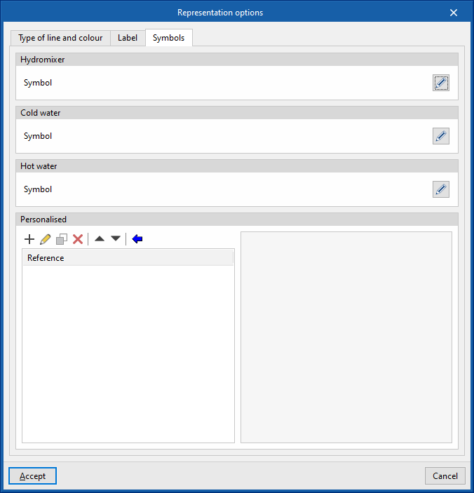
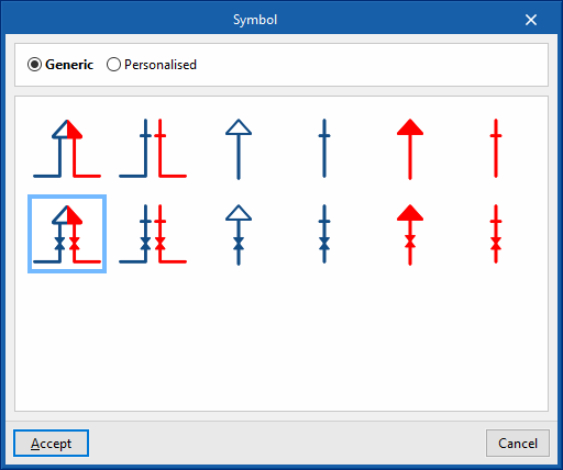
- “Symbols” tab
- Hydromixer (Symbol), Cold water (Symbol), Hot water (Symbol)
Selects the symbol used in the graphical representation of the water supply system consumption from the generic symbols available or the previously created customised symbols. - Personalised
Creates customised symbols using a drawing editor or imports symbols contained in DXF, DWG or DWF files saved on disk.
- Hydromixer (Symbol), Cold water (Symbol), Hot water (Symbol)
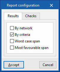
Report configuration
Configures the information that appears in the water supply system reports.
- Results
Configures the information that appears in the results report.- By network (optional)
- By criteria (optional)
- Worst case span (optional)
- Most favourable span (optional)
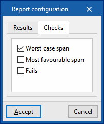
- Checks
Configures the information that appears in the check report.- Worst case span (optional)
- Most favourable span (optional)
- Fails (optional)
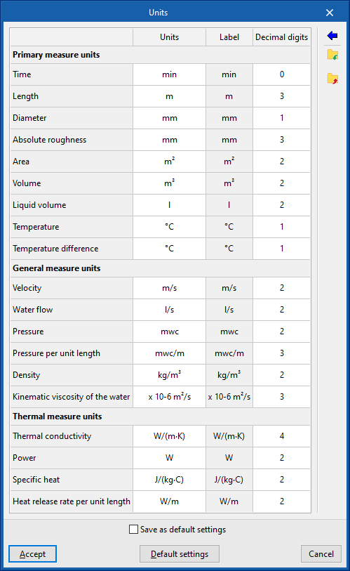
Units
Configures the units, the label and the number of decimal places for each of the magnitudes related to the water supply system:
- Primary measure units (Time, Length, Diameter, Absolute roughness, Area, Volume, Liquid volume, Temperature, Temperature difference)
- General measure units (Velocity, Water flow, Pressure, Pressure per unit length, Density, Kinematic viscosity of the water)
- Thermal measure units (Thermal conductivity, Power, Specific heat, Heat release rate per unit length)
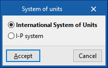
By using the "Import one of the predefined systems of units" option, available on the right-hand side of the panel, one of the following systems of units can be imported:
- International System of Units
Imports the units of the International System of Units. - I-P system
Imports the units of the I-P (Inch-Pound) or imperial system.