Setting the analysis and drawing options for the water evacuation system
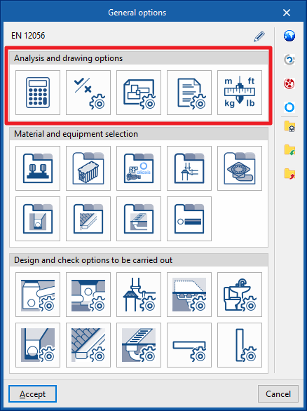
In the "Installation" tab of the "Water Systems" tab, in the "General Options" of the "Project" group in the main toolbar, the "Analysis and drawing options" of the water supply system can be configured:

- Calculation options
- General checks
- Representation options
- Report configuration
- Units
By using the "Import configuration" option, available on the right-hand side of the "General options" panel, this data can be automatically generated for different national and international standards. Similarly, data from different manufacturers can be imported by clicking on the options with their logo.
The other options in the right-hand column are for importing and exporting the complete configuration of the "General options" panel to files on disk, as well as selecting a file with initial values for creating a new job.
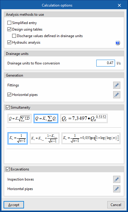
Calculation options
Defines the general data and criteria for the design of the water evacuation system.
- Analysis methods to use
- Simplified entry (optional)
If this option is activated, the panels for entering and editing the elements in the system have a simplified appearance and don't need to be defined by the user. - Design using tables (optional)
PerActivates the design using tables in the system.- Discharge values defined in drainage units (optional)
When this option is activated, the program allows users to enter the drainage units associated with each discharge from "Discharges", in the "Design and check options to be carried out" section of the "General options".
- Discharge values defined in drainage units (optional)
- Hydraulic analysis (optional)
Activates the hydraulic analysis of the system. The help button on the right allows users to consult the expressions used. The diameter of horizontal pipes is checked with the Manning formula, while the diameter of vertical pipes is checked with the Dawson and Hunter formula (for wastewater) and the Wyly-Eaton formula (for stormwater).
- Simplified entry (optional)
- Drainage units
- Drainage units to flow conversion
Defines the conversion factor from drainage units to flow units.
- Drainage units to flow conversion
- Generation
- Fittings (optional)
Selects the type of fitting to be assigned to the pipe joints when using the tools for the automatic generation of fittings available in the "Fittings" group of the main toolbar. The library of fittings can be configured in "Fittings" in the "Design and check options to be carried out" section of the "General options".- Elbow 45º
- Elbow 90º
- Tee 45º
- Tee 90º
- Horizontal pipes (optional)
Selects the type of horizontal pipe that the program assigns to each span of the system during the analysis, in the event that the "Pipe reference" section is kept unlocked in each horizontal pipe entered in the model. The horizontal pipe types can be created in "Horizontal pipes, in the "Design and check options to be carried out" section of the "General options".- Foul water (Discharge, Discharges, Floor trap, Cleanout, Drainpipe, Inspection box, Others)
- Rainwater (Discharge, Discharges, Floor trap, Cleanout, Drainpipe, Inspection box, Others)
- Fittings (optional)
- Simultaneity
Selects and defines the simultaneity analysis methods in the system. If necessary, it is possible to specify a different simultaneity method for each pipe defined in "Horizontal pipes / Vertical pipes" in the "Design and check options to be carried out" section of the "General options".- Q = K (Σ UD)1/2
Defines the simultaneous flow rate (Q) as a function of the sum of discharge units (DU) and the K coefficient. This coefficient can be entered in the box immediately below. The wizard on the right allows importing default values of the K coefficient for different cases of sanitary appliance use. - Q = Kn Σ Qi
Defines the simultaneous flow (Q) as a function of the sum of the instantaneous flows (Qi) and the Kn coefficient. This coefficient depends on the number (n) of discharges and its calculation expression takes different forms, which are shown and selected in this section. - Qc = 7.3497 × Qa0.5352
Defines the simultaneous or calculation flow rate (Qc) as a function of the accumulated flow rate (Qa).
- Q = K (Σ UD)1/2
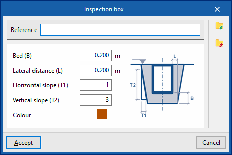
- Excavations
Defines the geometric properties of the transverse sections of the excavation of the following elements in the system, their reference and the colour of the representation. The defined excavation sections can be subsequently selected in the inspection box or horizontal pipe types created in "Inspection boxes / Horizontal pipes", in the "Design and check options to be carried out" section of the "General options".- Inspection boxes (Reference, Bed (B), Lateral distance (L), Horizontal slope (T1), Vertical slope (T2), Colour)
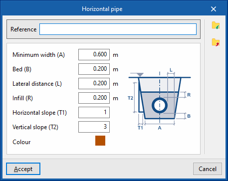
- Horizontal pipes (Reference, Minimum width (A), Bed (B), Lateral distance (L), Infill (R), Horizontal slope (T1), Vertical slope (T2), Colour)
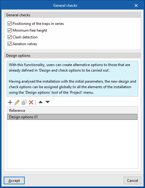
General checks
Defines the general checks of the water evacuation system.
- General checks
- Positioning of the traps in series (optional)
Check for the existence of traps arranged in series in the system. - Minimum free height (optional)
Checks that the system complies with the minimum free height defined for each floor. - Clash detection (optional)
Performs clash detection between overlapping elements in the system. - Aeration valves (optional)
Checks the need for aeration valves in the system.
- Positioning of the traps in series (optional)
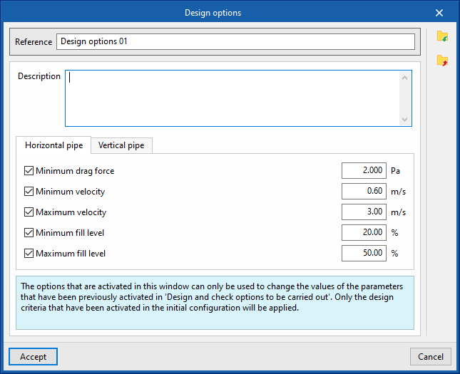
- Design options
With this feature, users can configure alternative design options globally for all the elements in the system. The parameters activated and entered in this window are only used to change the values of the parameters that are previously activated in each type of element defined in the "General options", from where the "Design and check options to be carried out" are accessed. Furthermore, once defined, these options will not be applied to the design of the system until the user assigns them using the "Design options" option in the "Project" group of the top tool menu in the general interface.- Reference
- Description
- "Horizontal pipe" tab
- Minimum drag force (optional)
- Minimum velocity (optional)
- Maximum velocity (optional)
- Minimum fill level (optional)
- Maximum fill level (optional)
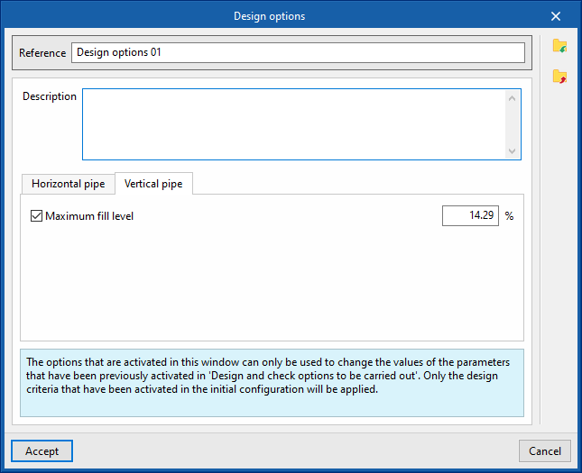
- "Vertical pipe" tab
- Maximum fill level (optional)
Representation options
Configures the graphical representation of the elements in the water evacuation system.
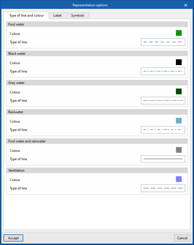
- “Type of line and colour” tab
Modifies the type of line and the colour used in the graphical representation of the different types of pipes.- Foul water (Colour, Type of line)
- Black water (Colour, Type of line)
- Grey water (Colour, Type of line)
- Rainwater (Colour, Type of line)
- Foul water and rainwater (Colour, Type of line)
- Ventilation (Colour, Type of line)
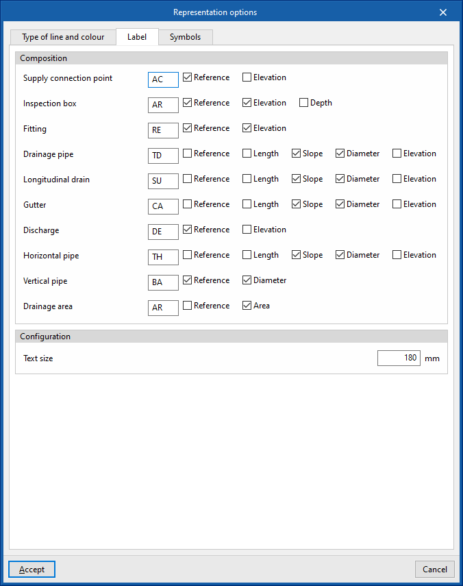
- “Label” tab
Adjusts the information displayed in the labels of the different elements in the water supply system and their text size.- Composition (Supply connection point, Meter, Fitting, Manifold, Tank, Pumping system, Hot water production, Heat exchanger, Consumption, Pipe)
- Configuration
- Text size
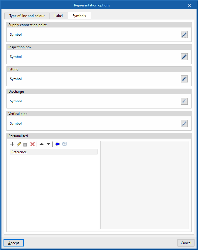
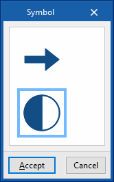
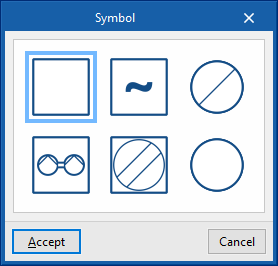
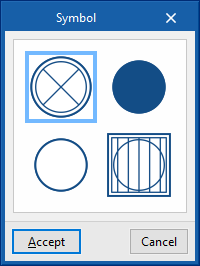
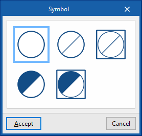
- “Symbols” tab
- Punto de acometida (Símbolo), Arqueta (Símbolo), Accesorio (Símbolo), Descarga (Símbolo), Bajante (Símbolo)
Selects the symbol used in the graphic representation of the elements of the water evacuation installation from the generic symbols available or from the previously created customised symbols. - Personalised
Creates customised symbols using a drawing editor or imports symbols contained in DXF, DWG or DWF files saved on disk.
- Punto de acometida (Símbolo), Arqueta (Símbolo), Accesorio (Símbolo), Descarga (Símbolo), Bajante (Símbolo)
Report configuration
Configures the information that appears in the water supply system reports.
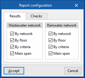
- Results
Configures the information that appears in the results report.- Wastewater network
- By network (optional)
- By floor (optional)
- By criteria (optional)
- Main span (optional)
- Rainwater network
- By network (optional)
- By floor (optional)
- By criteria (optional)
- Main span (optional)
- Wastewater network
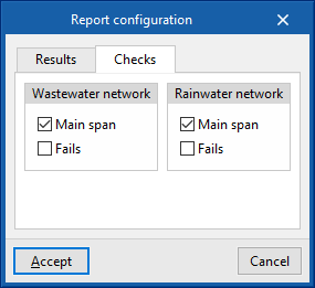
- Checks
Configures the information that appears in the check report.- Wastewater network
- Main span (optional)
- Fails (optional)
- Rainwater network
- Main span (optional)
- Fails (optional)
- Wastewater network
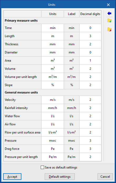
Units
Configures the units, the label and the number of decimal places for each of the magnitudes related to the water evacuation system:
- Primary measure units (Time, Length, Diameter, Absolute roughness, Area, Volume, Liquid volume, Temperature, Temperature difference)
- General measure units (Velocity, Water flow, Pressure, Pressure per unit length, Density, Kinematic viscosity of the water)
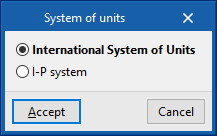
By using the "Import one of the predefined systems of units" option, available on the right-hand side of the panel, one of the following systems of units can be imported:
- International System of Units
Imports the units of the International System of Units. - I-P system
- Imports the units of the I-P (Inch-Pound) or imperial system.