Selecting the materials and equipment for the water evacuation system
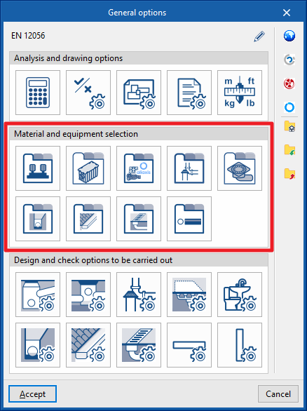
In the "Installation" tab of the "Water Systems" tab, in the "General options" from the "Project" group in the main toolbar, the "Material and equipment selection" of the following elements of the water evacuation system can be carried out:

- Pressure pump catalogue
- Catalogue of grease and hydrocarbon separators and bio-filtration systems
- Inspection box
- Fittings catalogue
- Drains catalogue
- Drainage pipes catalogue
- Gutter catalogue
- Longitudinal drains catalogue
- Pipes catalogue
Si se utiliza la opción "Importar configuración", disponible a la derecha del By using the "Import configuration" option, available on the right-hand side of the "General options" panel, this data can be automatically generated for different national and international codes. It is also possible to import data from different manufacturers by clicking on the options showing their logo.
The other options in the right-hand column can be used to import and export the complete configuration of the "General options" panel to files on disk, as well as to select a file with initial values for creating a new job.
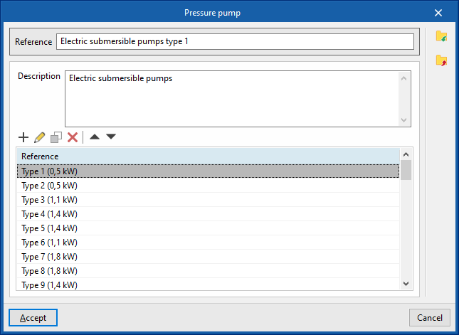
Pressure pump catalogue
Defines the catalogue of pressure pumps. The subsequent layout in the pumping inspection box model is carried out by means of the inspection box entry options in the "Registers" group of the program's general interface. The program allows users to select one of the pressure pump catalogues created when entering a particular inspection box, so that a type of inspection box must be used with the "Pressure pump" option activated, which is accessed through "Inspection boxes", in the "Design and check options to be carried out" section of the "General options".
When defining the pressure pump catalogues in this section, the following parameters must be specified:
- Reference
Pressure pump catalogue reference. - Description
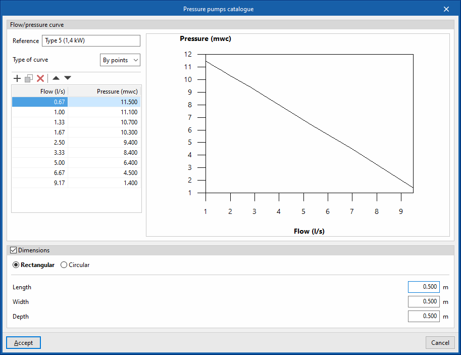
Pressure pump catalogue description. - Flow/Pressure curve
Defines the flow/pressure curves available in the pressure pump catalogue by adding entries in the table.- Reference
Curve reference. - Type of curve
- Midpoint
Enters the values defining the midpoint of the flow/pressure curve and displays a graph with the associated curve.- Flow
- Pressure
- By points
Enters flow/pressure point pairs and display a graph with the associated curve.- Flow
- Pressure
- Midpoint
- Dimensions (optional)
Defines the dimensions of the pressure pump.- Rectangular (Length, Width, Depth)
- Circular (Diameter, Depth)
- Reference
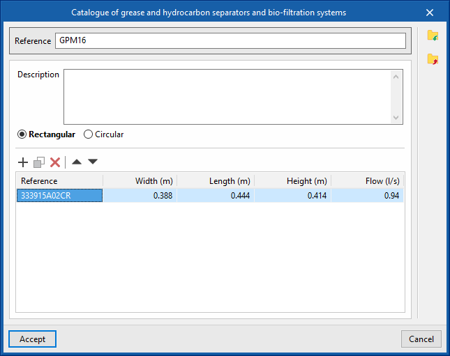
Catalogue of grease and hydrocarbon separators and bio-filtration systems
Defines the catalogue of grease and hydrocarbon separators and bio-filtration systems. The subsequent layout in the pumping inspection box model is carried out by means of the inspection box entry options in the "Registers" group of the program's general interface. The program allows users to select one of the catalogues of grease and hydrocarbon separators and bio-filtration systems created when entering a particular inspection box, so that a type of inspection box must be used with the "Grease separator" option activated in "Inspection boxes", in the "Design and check options to be carried out" section of the "General options".
When defining the catalogues of grease and hydrocarbon separators and bio-filtration systems in this section, the following parameters must be specified:
- Reference
Reference of the catalogue of grease and hydrocarbon separators and bio-filtration systems. - Description
Description of the catalogue of grease and hydrocarbon separators and bio-filtration systems. - Type (Rectangular / Circular)
Defines the reference, dimensions and flow rate of each grease and hydrocarbon separator or each bio-filtration system by adding entries in the table, after indicating whether they are rectangular or circular.- Rectangular
- Reference, Width, Length, Height, Flow
- Circular
- Ordering Number, Diameter, Head, Flow
- Rectangular
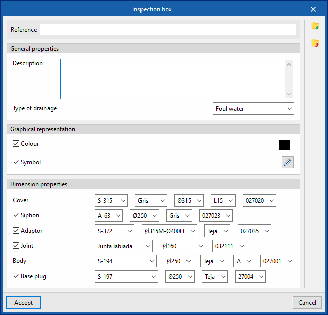
Inspection box
Defines the inspection boxes of the manufacturer's collection systems. The subsequent selection and layout of these elements in the model can be carried out using the options for entering collection systems in the "Records" group in the program's general interface.
To define the inspection boxes in this section, first it is necessary to download the catalogue of the collection system after logging in to the Open BIM Database. Then, when creating a inspection box in this section, the following parameters must be specified:
- Reference
Inspection box reference. - General properties
- Description
- Type of drainage (Foul water / Black water / Grey water / Rainwater / Foul water and rainwater)
- Graphical representation
- Colour (optional)
- Symbol (optional)
- Dimension properties
Defines the dimension properties of each element by selecting a model from among those available.- Cover
- Siphon (optional)
- Adaptor (optional)
- Joint (optional)
- Body (optional)
- Base plug (optional)
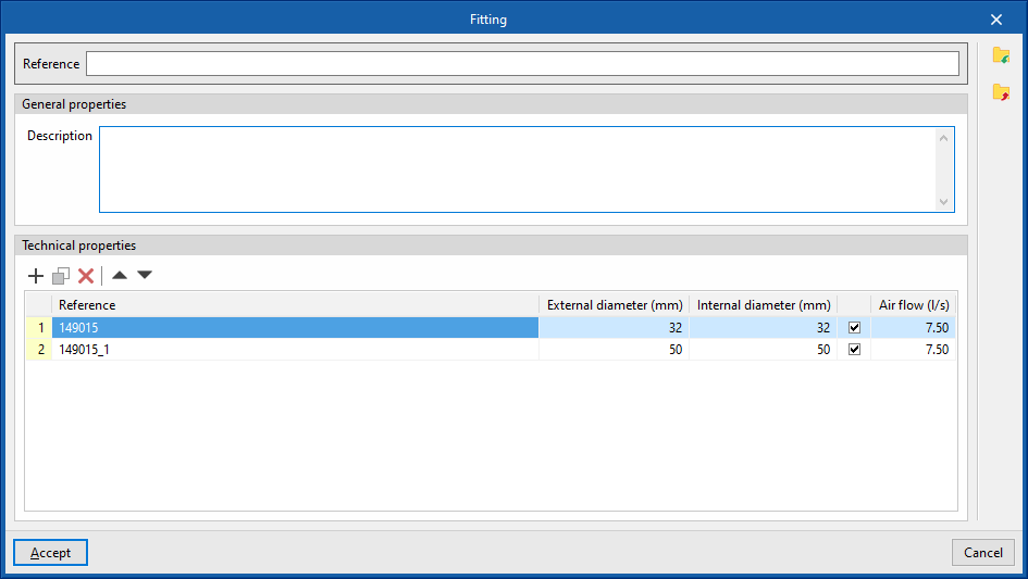
Fittings catalogue
Defines the catalogue of materials . The subsequent layout in the pumping inspection box model is carried out by means of the inspection box entry options in the "Registers" group of the program's general interface. The program allows users to select one of the catalogues of grease and hydrocarbon separators and bio-filtration systems created when entering a particular inspection box, so that a type of inspection box must be used with the "Grease separator" option activated in "Inspection boxes", in the "Design and check options to be carried out" section of the "General options".
Defines the dimension properties of each element by selecting a model from among those available.
- Reference
Material or equipment reference. - General properties
- Description
Material or equipment description.
- Description
- Technical properties
Enters the technical properties of the fitting by adding entries in the table.- Reference
- External diameter
- Internal diameter
- Air flow (optional)
Permissible air flow for aeration valves.
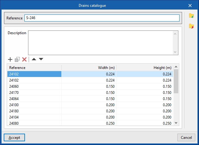
Drains catalogue
Defines the catalogue of materials corresponding to the drains. The materials defined here can be assigned to the drains created in "Downloads", in the "Design and check options to be carried out" section of the "General options", by activating the "Drain" and "Material" boxes. The subsequent layout of these elements in the model is done via the options in the "Downloads" group in the program's general interface.
When defining the drains in this section, the following parameters need to be specified:
- Reference
Material or equipment reference. - Description
Material or equipment description. - Properties
The properties of each drain in the series can be entered into the program by adding entries in the table.- Reference
- Width
- Height
Drainage pipes catalogue
Defines the catalogue of materials corresponding to the drainage pipes. The materials defined here can be assigned to the drainage pipes created in "Drainage pipes", in the "Design and check options to be carried out" section of the "General options". The subsequent layout of these elements in the model is carried out by means of the "Drainage pipes" option in the "Pipes" group in the program's general interface.
When defining the drainage pipes in this section, the following parameters must be specified:
- Reference
Material or equipment reference. - Description
Material or equipment description. - Manning’s coefficient
Coefficient used in Manning's formulation. - Properties
The properties of each drainage pipe in the series can be entered into the program by adding entries in the table.- Reference
- Nominal diameter
- External diameter
- Thickness
Gutter catalogue
Defines the catalogue of materials corresponding to the gutters. The materials defined here can be assigned to the gutters created in "Gutters", in the "Design and check options to be carried out" section of the "General options". The subsequent layout of these elements in the model is carried out by means of the "Gutter" option in the "Pipes" group in the program's general interface.
When defining the gutters in this section, the following parameters must be specified:
- Reference
Material or equipment reference. - Description
Material or equipment description. - Manning’s coefficient
Coefficient used in Manning's formulation. - Properties
The properties of each gutter in the series can be entered into the program by adding entries in the table.- Reference
- Nominal diameter
- External diameter
- Thickness
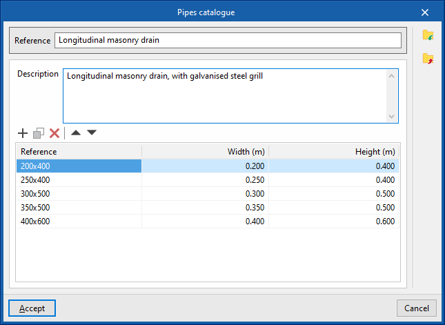
Longitudinal drains catalogue
Defines the catalogue of materials corresponding to the longitudinal drains. The selection and subsequent layout of these elements in the model is carried out by means of the "Longitudinal drain" option in the "Piping" group in the program's general interface.
When defining the longitudinal drains in this section, the following parameters must be specified:
- Reference
Material or equipment reference. - Description
Material or equipment description. - Properties
The properties of each longitudinal drain in the series can be entered into the program by adding entries in the table.- Reference
- Width
- Height
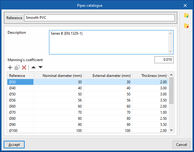
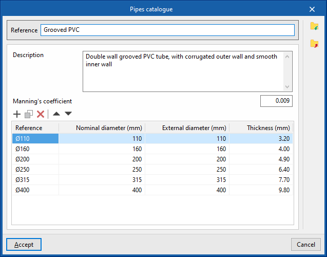
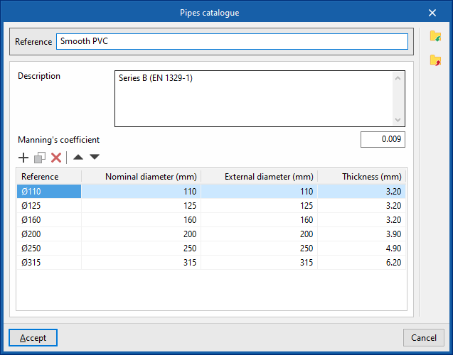
Pipes catalogue
Defines the catalogue of materials corresponding to the pipes. The materials defined here can be assigned to the horizontal and/or vertical pipes created in "Horiztonal pipes / Vertical pipes", in the "Design and check options to be carried out" section of the "General options". The subsequent arrangement of these elements in the model is carried out by means of the corresponding options in the "Pipes" group in the program's general interface ("Pipe", "Vertical pipe").
When defining the pipes in this section, the following parameters must be specified:
- Reference
Material or equipment reference. - Description
Material or equipment description. - Manning’s coefficient
Coefficient used in Manning's formulation. - Properties
The properties of each pipe in the series can be entered into the program by adding entries in the table.- Reference
- Nominal diameter
- External diameter
- Thickness