Entering drainage areas in the water evacuation system
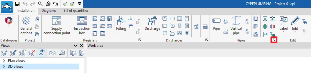
In the "Installation" tab of the "Sanitary Systems" tab, in the "Pipes" group of the main toolbar, there are options for inserting drainage pipes, gutters and longitudinal drains into the drainage system:

Pipe
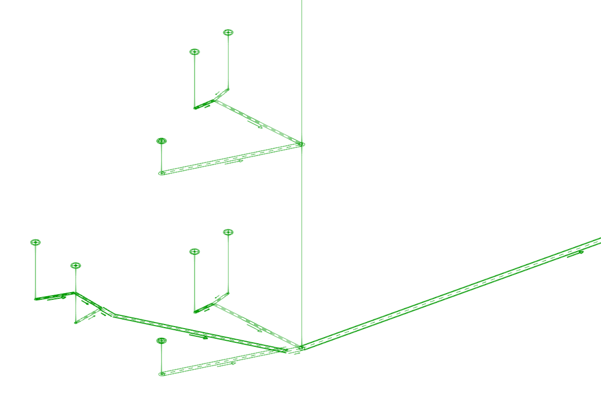
Inserts a pipe into the drainage system in any position, horizontally or vertically, either for rainwater and/or wastewater drainage or for ventilation.
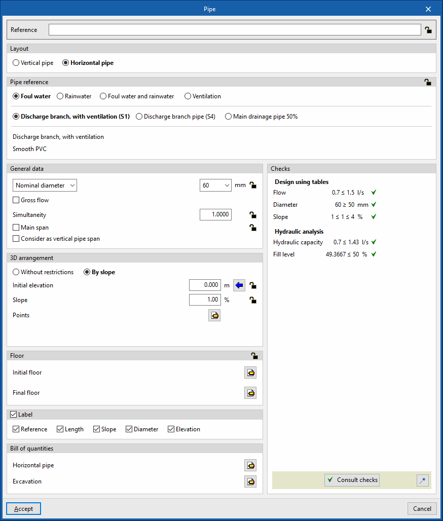
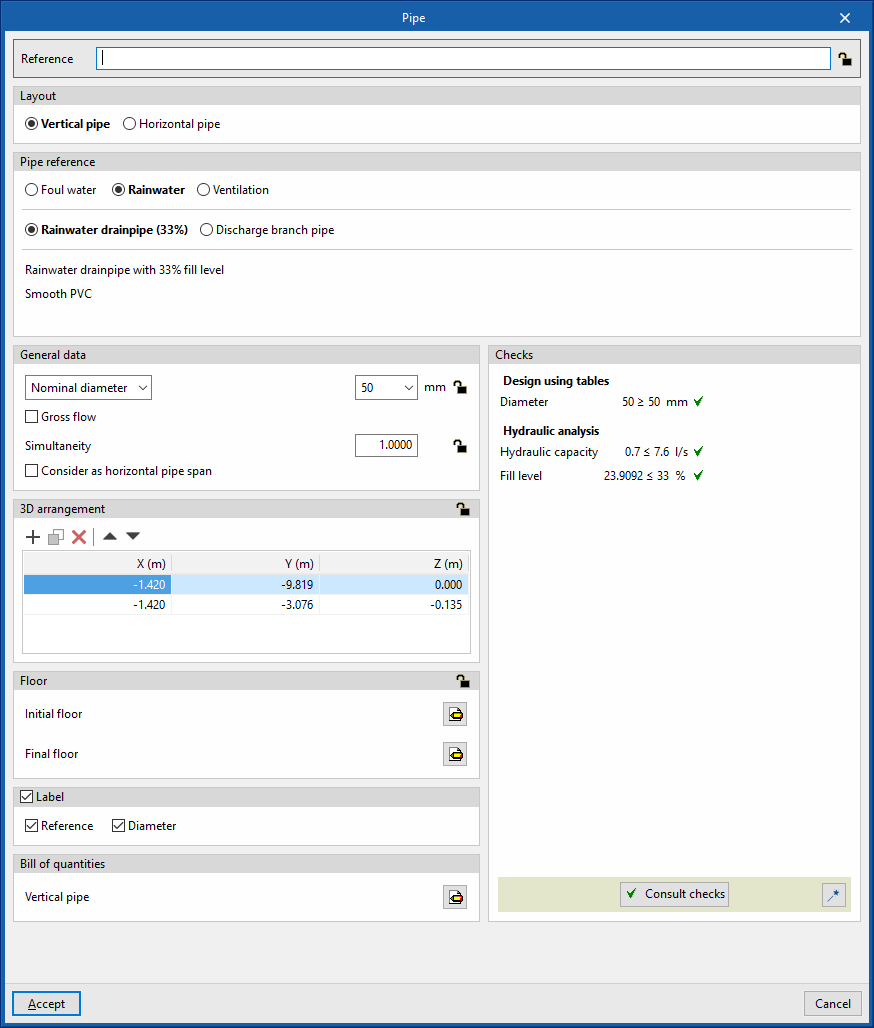
When entering or editing a pipe, the following parameters can be configured. Some parameters only appear if the "Simplified entry" option, which can be found in the "Design options" of the "General options", is kept deactivated:
- Reference
Element reference. This value can be locked or unlocked. If unlocked, the program will create or modify the reference when updating results. - Layout (Horizontal / Vertical)
Defines whether the pipe layout is horizontal or vertical. - Pipe reference
Selects the type of pipe by its reference and according to the type of drainage assigned to each one and the selected layout. These types can be created and edited in “Horizontal pipes / Vertical pipes” which can be accessed in the “Project” group when selecting “General options” and then "Design and check options to be carried out". - General data
Defines the element's general data. Some of these values can be locked or unlocked. If a value is locked, it is not modified when updating the results and remains unchanged.- Nominal diameter / External diameter / Internal diameter (Lock/Unlock)
Selects and defines the diameter of the pipe. - Drainage units (Lock/Unlock)
Defines the number of drainage units associated with the gutter. This option only appears if the "Discharge values defined in drainage units" checkbox is activated in the "Design options" of the "General options", and if "Drainage units" is selected in the "Design using tables" tab, within the "Analysis methods to use" of the pipe type chosen. - Design area (Lock/Unlock)
Defines the design area associated with the pipe. This option only appears if the "Discharge values defined in drainage units" checkbox is activated in the "Design options" of the "General options". If this value is unlocked, the program can modify it when updating results. - Gross flow (optional) (Lock/Unlock)
Defines the flow rate of the pipe and enables the "Hydraulic analysis" checks. - Simultaneity (Lock/Unlock)
Defines the simultaneity coefficient of the pipe. - Main span (optional) (Lock/Unlock)
Used to consider the pipe as a main span. The main spans are the main elements of the installation and impose the elevation and layout of the rest of the pipes that are connected to them. This option only appears in horizontal pipes. - Consider the pipe as a vertical pipe span (optional)
Used to consider the pipe as a vertical pipe span, deactivating the checks associated with the type of horizontal pipe selected. This option only appears in vertical pipes. - Consider the pipe as a horizontal pipe span (optional)
Used to consider the pipe as a horizontal pipe span, deactivating the checks associated with the type of horizontal pipe selected. This option only appears in horizontal pipes.
- Nominal diameter / External diameter / Internal diameter (Lock/Unlock)
- 3D layout
Defines the 3D layout of the element. This section only appears when editing a previously entered element.- In vertical pipes
In these pipes, the program provides a table that directly enters the absolute spatial coordinates X, Y and Z of the points on the polygonal line defining the axis of the element. - In horizontal pipes
In these pipes, the program provides a number of options for defining the 3D layout of the element:- Without restrictions
Directly enters the absolute X, Y and Z spatial coordinates of the points on the polygonal line defining the axis of the element. - By slope
Defines the 3D layout of the element by entering the on plan coordinates of the points through which it passes, the initial coordinate of the first point and the slope of the element. If the values for initial elevation and slope are unlocked, the program can adjust them when updating results.- Initial elevation (Lock/Unlock)
Defines the initial elevation of the element. - Slope (Lock/Unlock)
Defines the slope of the element. - Points
Defines the absolute X and Y plan coordinates of the points on the polygonal line defining the axis of the element.
- Initial elevation (Lock/Unlock)
- Without restrictions
- In vertical pipes
- Floor (Lock/Unlock)
Defines the data of the “Initial floor” and “Final floor” assigned to the pipe. This section only appears when editing a previously entered element. If this section is unlocked, the program can modify this data, which is generated according to the layout of the element in the model. Using the wizard available on the right, the data of a floor plan defined in the "Floor plans" section of the "Project" group can be imported.- Reference
- Initial elevation
- Installation depth
- Minimum free height
- Label (optional)
Manages the information visible in the element's label.- In vertical pipes
- Reference (optional)
- Diameter (optional)
- In horizontal pipes
- Reference (optional)
- Length (optional)
- Slope (optional)
- Diameter (optional)
- Elevation (optional)
- In vertical pipes
- Bill of quantities
Controls the generation of the element's bill of quantities using filters.- In vertical pipes
- Vertical pipe
- In horizontal pipes
- Horizontal pipe
- Excavation
- In vertical pipes
- Consult checks
Used to consult and list the checks carried out on the element, if defined in the selected drainage area type. - Design
This feature, accessed by clicking on the button in the bottom right-hand corner, is used to automatically design the parameters considered in the drainage area editing panel so that they comply with the defined checks.
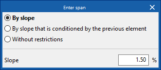
When inserting a horizontal pipe into the model, the program displays the "Enter span" dialogue box, which has the following options:
- By slope
Directly defines the value of the slope of the span. Then, the points defining the span in plan are entered in the model. The program will select "By slope" in the "3D layout" section of the span editing panel and will fill in the "Slope" value, without locking it. If it is kept unlocked, when designing the program this value can be modified according to its configuration parameters and the layout of the span in the installation.- Slope
- By slope that is conditioned by the previous element
This defines the span by slope without specifying its value. Then, the points defining the span in plan are entered in the model. The program will select "By slope" in the "3D layout" section of the span editing panel and will fill in the "Slope" value conditionally to the previous span. If it is kept unlocked, when designing the program, this value can be modified according to its configuration parameters and the layout of the span in the installation. - Without restrictions
Used to freely enter the points defining the span in the space. The program will select ‘No restrictions’ in the ‘3D layout’ section of the span editing panel.
Therefore, in the case of horizontal pipes, the program will use the slope parameters defined in the "Analysis methods to be used" tab and, within this, in "Design by tables", within the defined configuration (from "General options" and in the "Design options and checks to be carried out" section, accessing "Horizontal pipes") for each type of pipe entered. This tab appears if the "Design by tables" option is activated in the "General options" (by accessing the "Analysis and design options" and then "Analysis options"). It will also apply the minimum and/or maximum slope criteria defined in the "General data" tab, available in the same window for each type of pipe.
The value of the slope may also vary depending on the layout of the span in the system, to accommodate other spans imposed by the geometry of the system.
Creating intersections
The program has two tools to manage the connections or intersections between vertical pipes and horizontal pipes:
- Create intersection between a vertical pipe and a horizontal pipe
Selects a specific vertical pipe and a horizontal pipe and creates the intersection between them. - Create intersections between vertical pipes and all pipes in contact with them
Automatically creates all intersections between the vertical pipes in the model and the horizontal pipes in contact with them.
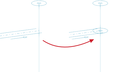
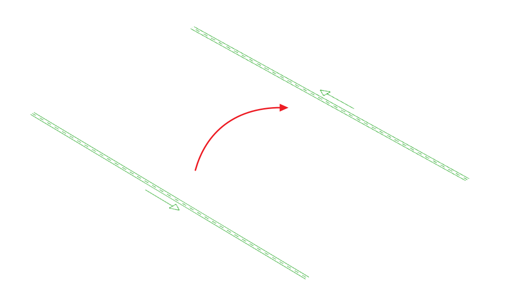
Changing the direction of the flow
Changes the direction of flow of a span in the drainage system.
For spans entered with the "Pipe" option, the default flow direction is defined according to the order of insertion of points. The flow direction can be displayed by means of a symbol next to the middle part of the span.
For spans entered with the "Vertical pipe" option, the default flow direction is downward. If necessary, this option can be used to achieve an upward flow direction. In the latter case, the program displays a symbol indicating the flow direction over the middle part of the span.
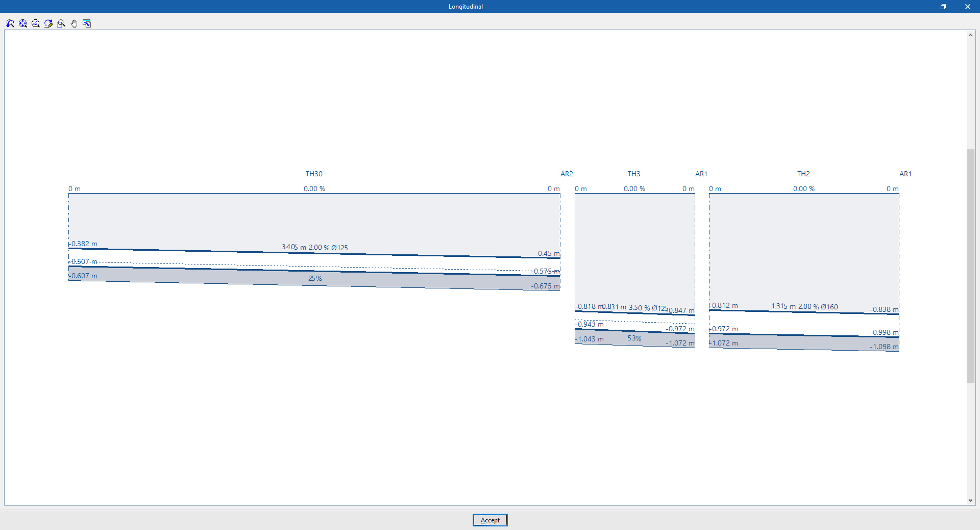
Longitudinal
Used to display the longitudinal section of the excavation in several consecutive spans of the water drainage system, after selecting the starting and end points or spans of the desired section in the model.
To be able to use this option, the "Excavations" option must be activated in the "Design options" of the "General options", where the excavation sections available for the inspectio boxes and horizontal pipes can be defined. Then, these excavation sections are assigned to the horizontal pipes defined in "Design and check options to be carried out", in the "General options", and used in the model.
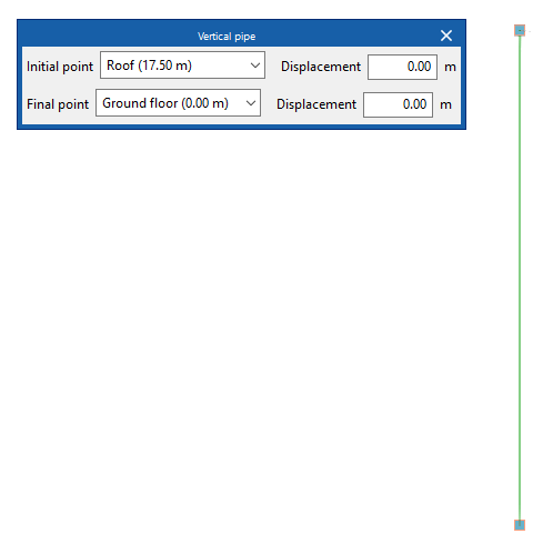
Vertical pipe
Allows a vertical pipe to be inserted into the water drainage system, either for rainwater and/or wastewater drainage or for ventilation.
By clicking on this option, the program can be used to define the characteristics of the vertical pipe by means of an editing panel identical to the one that appears when using the "Piping" option, in the event that the "Vertical pipe" type is selected in this panel.
Then, when a vertical pipe is inserted in the model, the program displays the "Vertical pipe" dialogue box, where the level associated with the "End point" of the pipe is defined, together with a "Displacement" above the indicated level, expressed in positive or negative values.
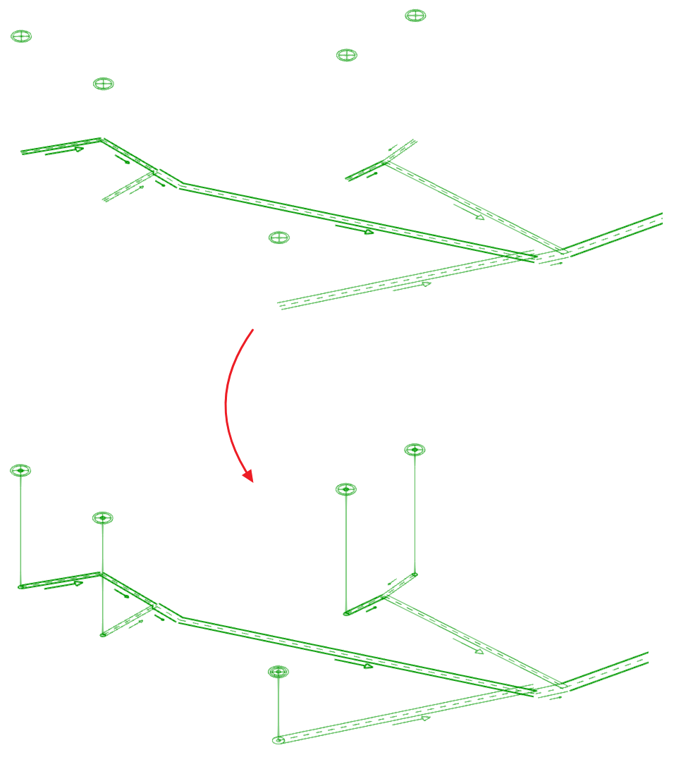
Generating vertical pipes
The program offers two utilities for the automatic generation of vertical pipes connecting other elements (such as pipes or discharges) previously laid out in the model.
- The first option generates the vertical pipes at all points of the job where possible.
- The second option generates the vertical pipes between the elements selected by the user, if possible.
After using any of these tools, the program reports the number of horizontal pipes generated. From here, the pipes created in the process can be edited or deleted, if desired.
This tool only generates a vertical pipe between two elements located at different heights if their ends, or points where the connecting vertical pipe is to be placed, have the same plan coordinates.
These options are equivalent to those available in "Design and check options to be carried out" under "General options" in the "Project" group.