The use of BIM (Building Information Modelling) methodology is a trend that is becoming a mandatory legal requirement for the design of buildings and public works. The advantages of this workflow (less wasting of both time and resources in the design phase, more efficient data management during the construction of the building and throughout its life cycle, and construction savings of around 20%) suggest that the different specialists in the industry should opt to work in a synchronised way.
BIM has influenced the traditional design process by providing a highly collaborative process that allows various parties and members of the project to work simultaneously. In this context, we are going to analyse and propose a way of working to integrate reinforced concrete structures into the BIM workflow. A speciality that, due to its very nature (concrete sections and reinforcement design), is still causing problems among professionals who want to work in a BIM environment.
In order to meet the needs of users who are designing with BIM, concrete design software must comply with the following critical aspects:
- Solving all cases covered by the design codes.
- Using stable information exchange processes that do not depend on the software used.
- Reducing manual entry of data that has been previously entered in other software.
- Displaying results according to the latest technological framework.

Work proposal for achieving these objectives
BIMserver.center's work proposal for modelling concrete structures in BIM is based on working with IFC files that are generated using a 3D geometric model produced by any architectural modelling software, just like the other specialist applications (CYPE offers the free CYPE Architecture program on our platform).
This geometric model is shared on the BIMserver.center platform, allowing direct communication between all users and applications involved in the project. This file format allows users to use the applications of their choice, as long as they import and export IFC files.
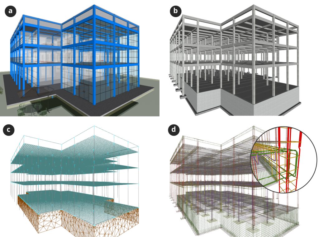
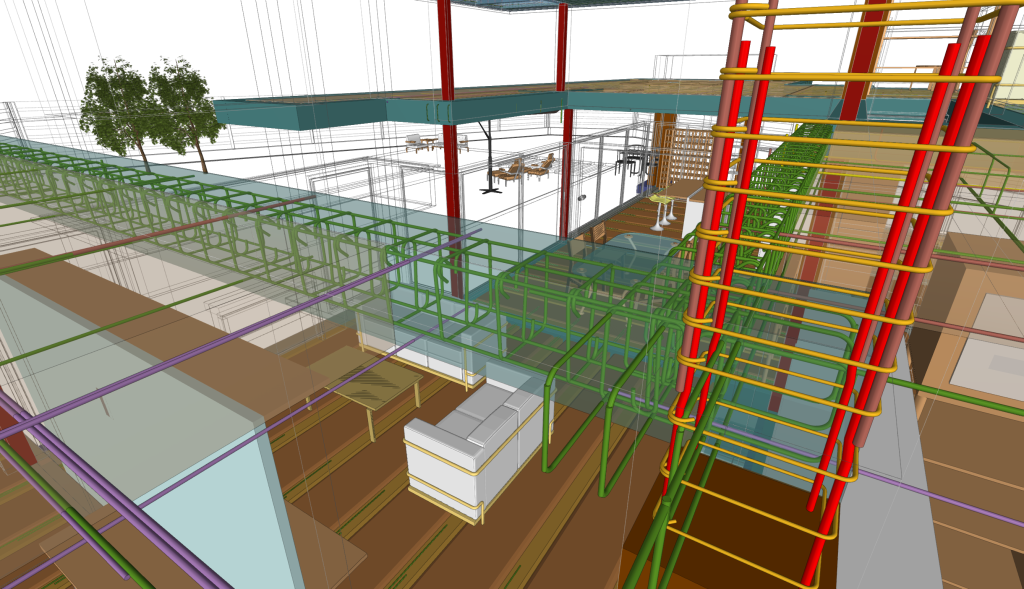
a) Initial proposal for the structure, entered into the project during the conceptual design phase. b) Structural model developed from the architectural model. c) Analytical model. d) Reinforcement detailing model.
Generating the different models of the structure
To work in this BIM environment, the software used by professionals must be able to generate the different models of the structure in a decoupled way:
- Architectural model (external walls, partitions, spaces, levels, etc.). We have CYPE Architecture on our platform.
- Structural model (beams, columns, slabs, walls, etc.); analytical model (finite elements, outline conditions, reactions, etc.); and model that meets the codes (reinforcement ratios, resistant sections, etc.). In order to generate these models, the following programs are available: CYPECAD, CYPE 3D, CYPE Connect and StruBIM Shear Walls.
- Detailing model (3D position of reinforcement, bending of stirrups, etc.). In BIMserver.center, we have the following applications: StruBIM Rebar (for concrete), StruBIM Steel (for steel) and CYPECAD, a program that already generates the reinforcement detailing model in its latest updates.
- Fabrication model and implementation (machine sequences, interactive augmented reality, etc.). CYPECAD and StruBIM Steel provide these models.
As we have seen, in BIMserver.center we have several programs that can carry out all these models and decouple them from each other so that, once their needs have been met, work can be carried out integrally via the IFC files. So, for example, CYPECAD can produce the structural model and the analytical model, while the compliance of shear walls according to ACI 318 can be analysed in StruBIM Shear Walls.
If the designer is working on a mixed concrete and steel structure, both the concrete part and the foundations are solved in CYPECAD and the steel parts in CYPE 3D, CYPE Connect and StruBIM Steel.
Goals that can be achieved with the use of BIM in structures
Objective 1: Solve the cases covered by the design codes.
To solve this objective, at BIMserver.centre we have specific CYPE software that checks the structural model in accordance with the selected design code, thanks to the results of the analytical model. For example, StruBIM Shear Walls can check shear walls after importing them together with their forces, the latter coming from the finite element analysis of the analytical model.
However, this is just one example of the regulatory cases that can be solved with the software available at BIMserver.center, as tools such as CYPECAD or CYPE 3D have structural code compliance (from different countries) in their DNA.
The imported and exported data in this BIM work process should be the basic data and results of the speciality to be solved in each of the models so that all programs can exchange information with each other in a stable way.
Objective 2: Use stable information exchange processes that do not depend on the software used.
As we have seen above, the exchange of information between programs must be carried out using the necessary data so that it does not need to rely on the ergonomics layers provided by each program (meaning that a program with more ergonomic layers is more intuitive). The only thing that can be transmitted between different programs, even from other software manufacturers, is the necessary data. Transmitting this data (the geometry, materials and forces in the example shown above) between applications achieves the goal of stable information exchange.
Not working with this necessary data leads to situations where one program uses some data while a second application uses different data to solve the same problem. This makes it impossible for the two to communicate with each other. In BIMserver.center, the StruBIM software suite gives users the option to insert basic data, as well as a higher level of data using ergonomics layers.
Objective 3: Reduce manual input of data that has already been entered into other software.
This objective is met by employing the philosophy shown in the previous section. Programs can import all the information they need (previously entered into another program to solve a previous model of the structure) without the need to re-enter the data manually.
This objective is essential to increase specialists' productivity, as it is estimated that the manual data entry process accounts for 80% of the time spent resolving a given discipline within a project.
Objective 4: Show results according to the latest technological framework.
One of the main objectives of BIM is to provide better views of the project in order to reduce errors and improve the understanding of the adopted solutions. 3D viewing in programs has always been an important function for BIM software. However, the opportunities created by new technologies such as augmented reality and virtual reality also need to be taken into account.
In BIMserver.center, users can obtain a 3D view of the different models and, at the same time, take advantage of all the benefits of augmented reality because all projects developed using the BIMserver.center workflow can be immediately displayed in AR using the application from our platform on handheld devices and with no need to carry out any prior steps.
The viewing of the results should not be restricted to the structural elements, but it is also advisable to view the design results, such as the interaction surface areas of columns and beams. This can be carried out in BIMserver.center and makes it easier to acquire information at any stage of the project, even in the maintenance stage, when renovations have to be carried out.