New features

2018.i version

7 February 2018
Index

New features of the 2018.i version

StruBIM Embedded Walls (new program)

StruBIM Embedded Walls is the new version of Embedded Retaining Walls that is integrated in the Open BIM workflow. Both programs have the same features, and design and check different types of embedded walls (reinforced concrete, pile, mini pile, steel sheet pilings and generic embedded walls) for building and civil works.

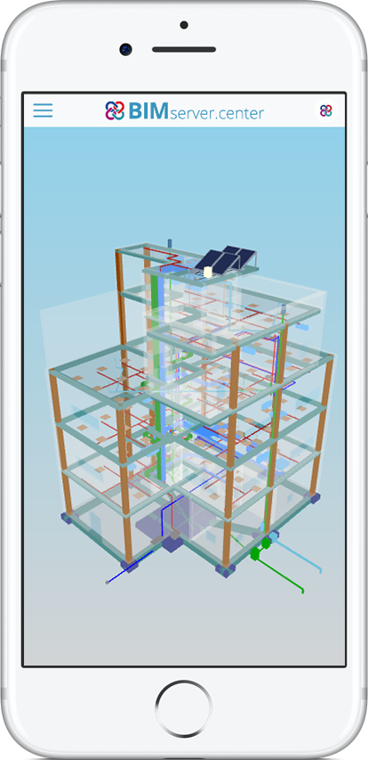
StruBIM Embedded Walls is downloaded exclusively from the BIMserver.center platform. Users whose license is updated to the 2018 version of “Embedded Retaining Walls” can also use “StruBIM Embedded Walls” with any of the modules they have acquired. To do so, they will simply have to copy the permits of their local physical or electronic license key to BIMserver.center.

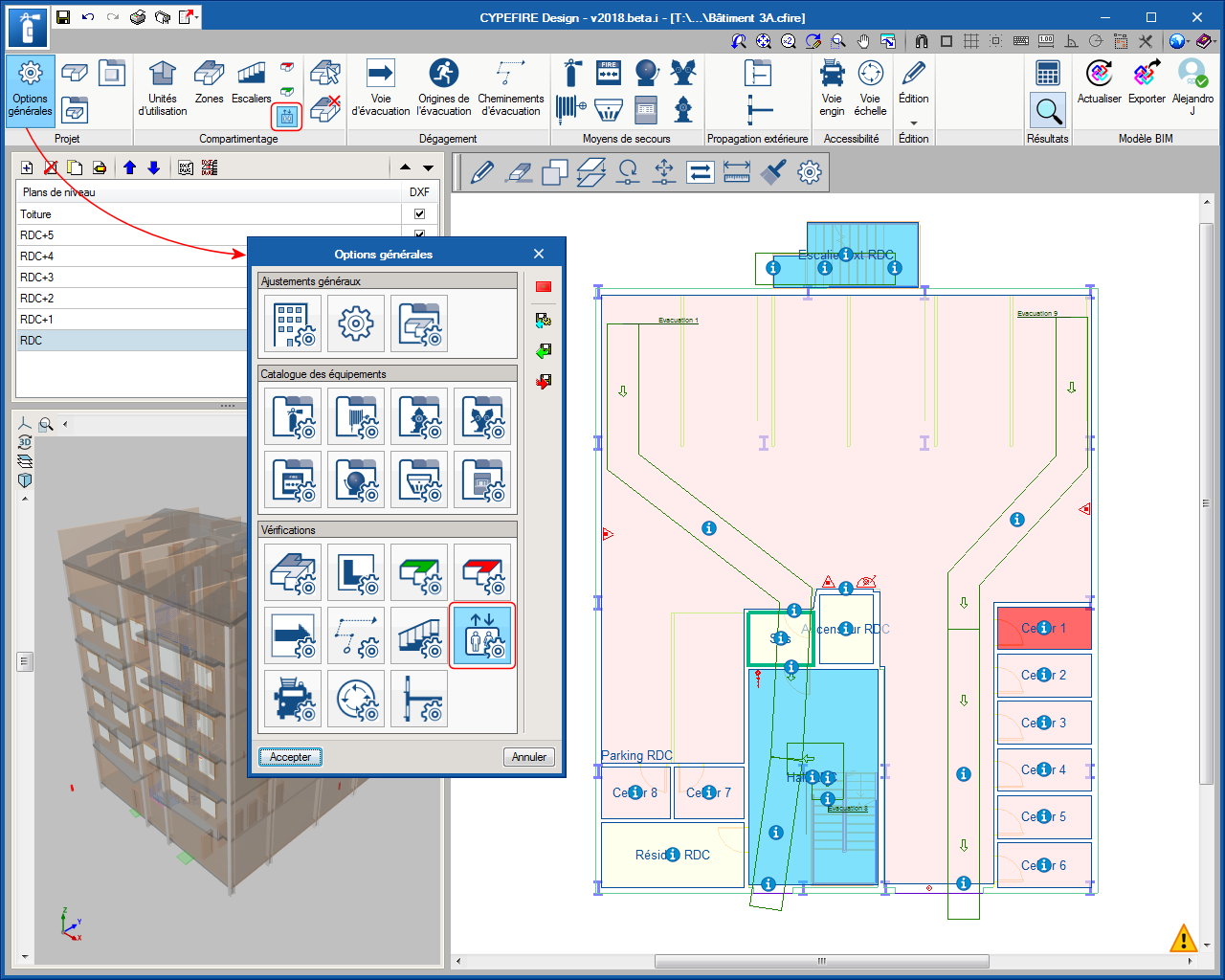
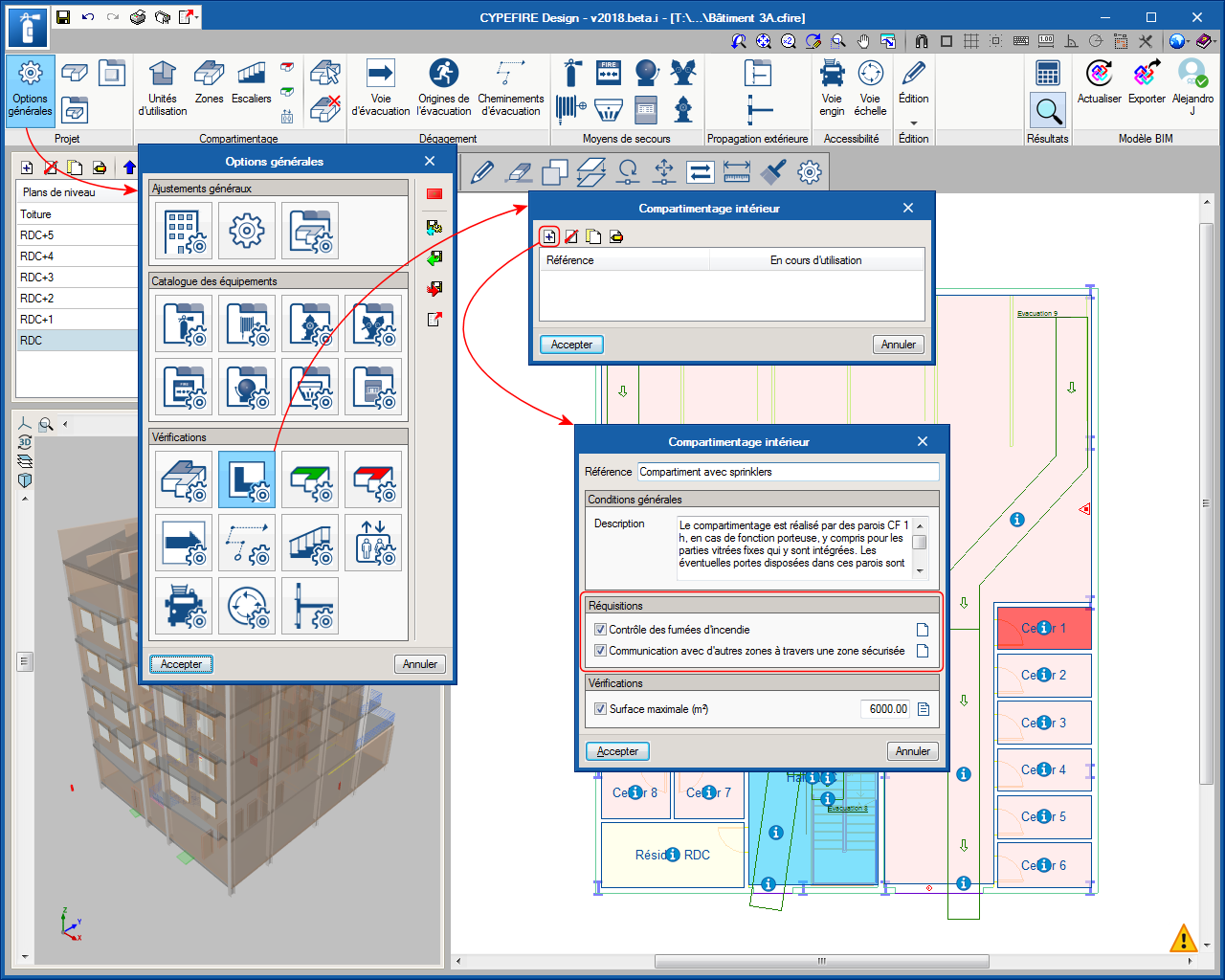
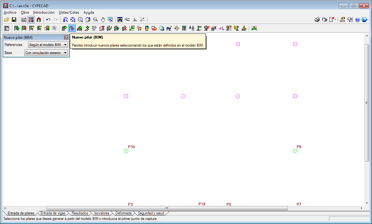
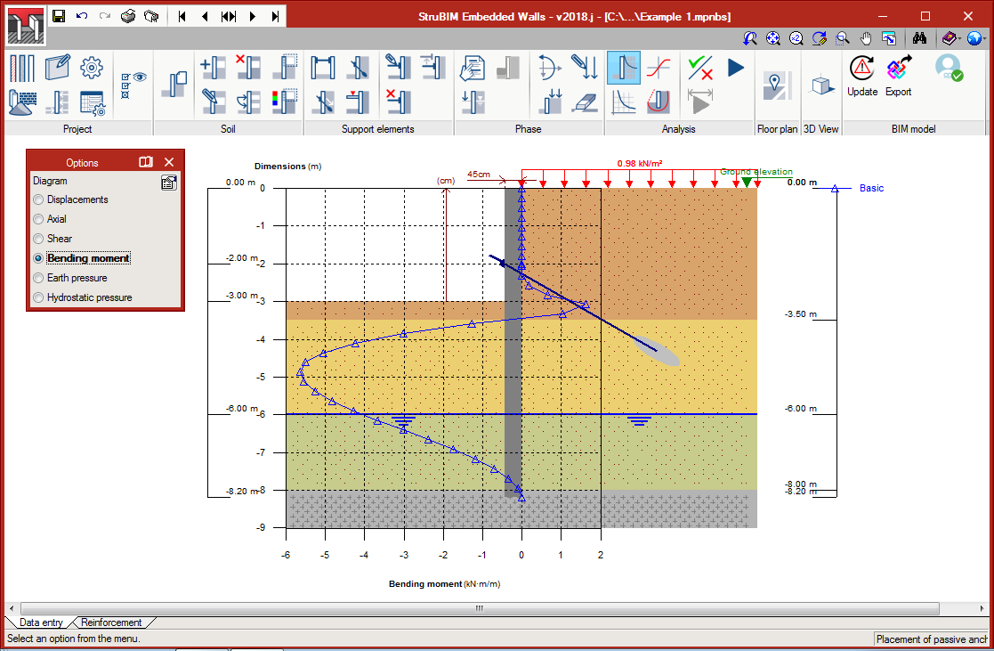
The workspace of StruBIM Embedded Walls is slightly different to that of Embedded Retaining Walls. The buttons that represent the program tools look and have been organised differently, although they have the same functions. The advantage of using StruBIM Embedded Walls is its integration in the Open BIM workflow.

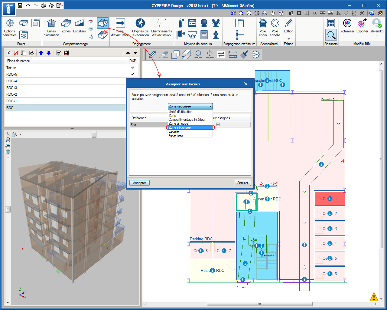
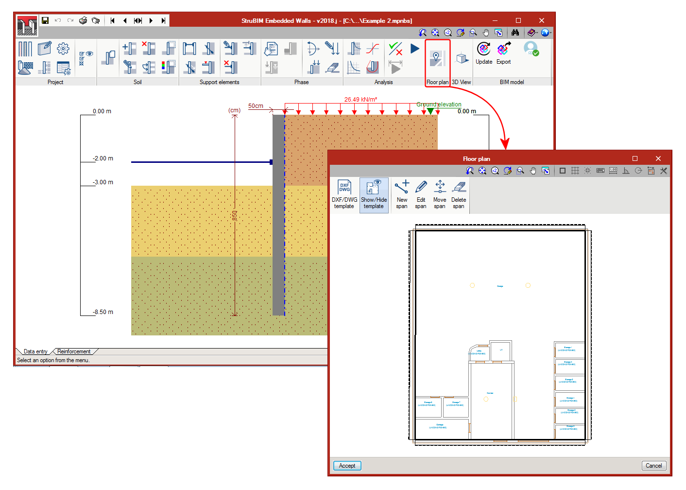
StruBIM Embedded Walls includes an additional tool that allows users to define the path of the walls on plan (with the option to import DXF or DWG files). This way, when the project is exported to the BIM model, each span of the wall will be placed at its position in the architectural model.

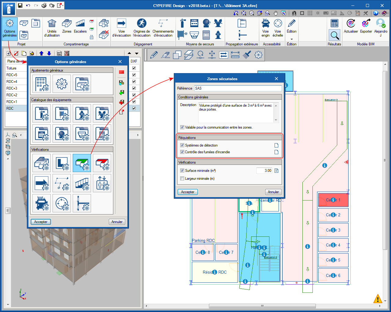
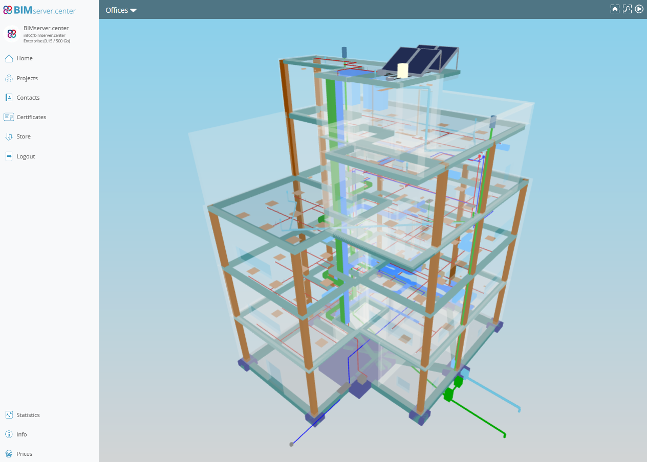
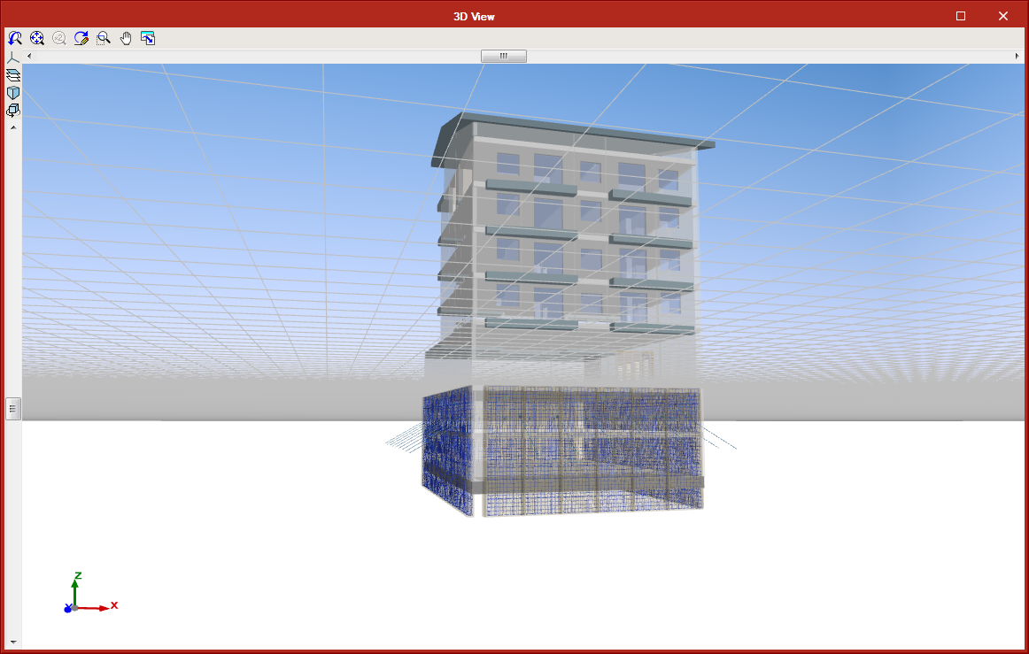
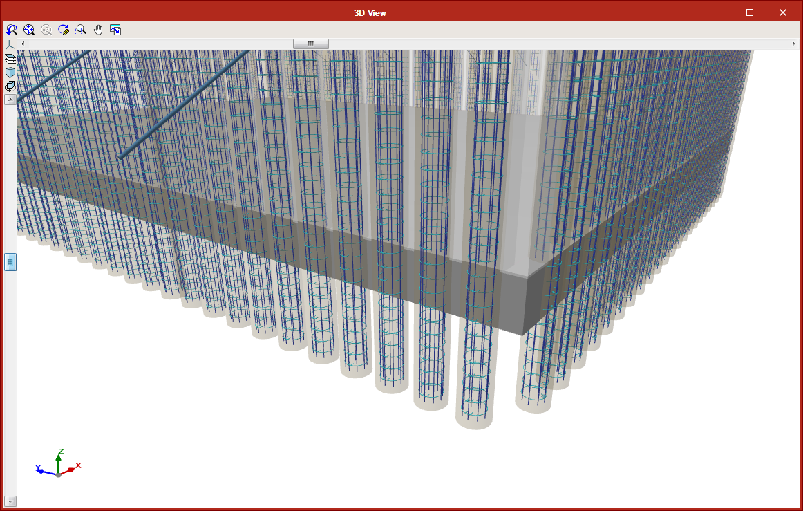
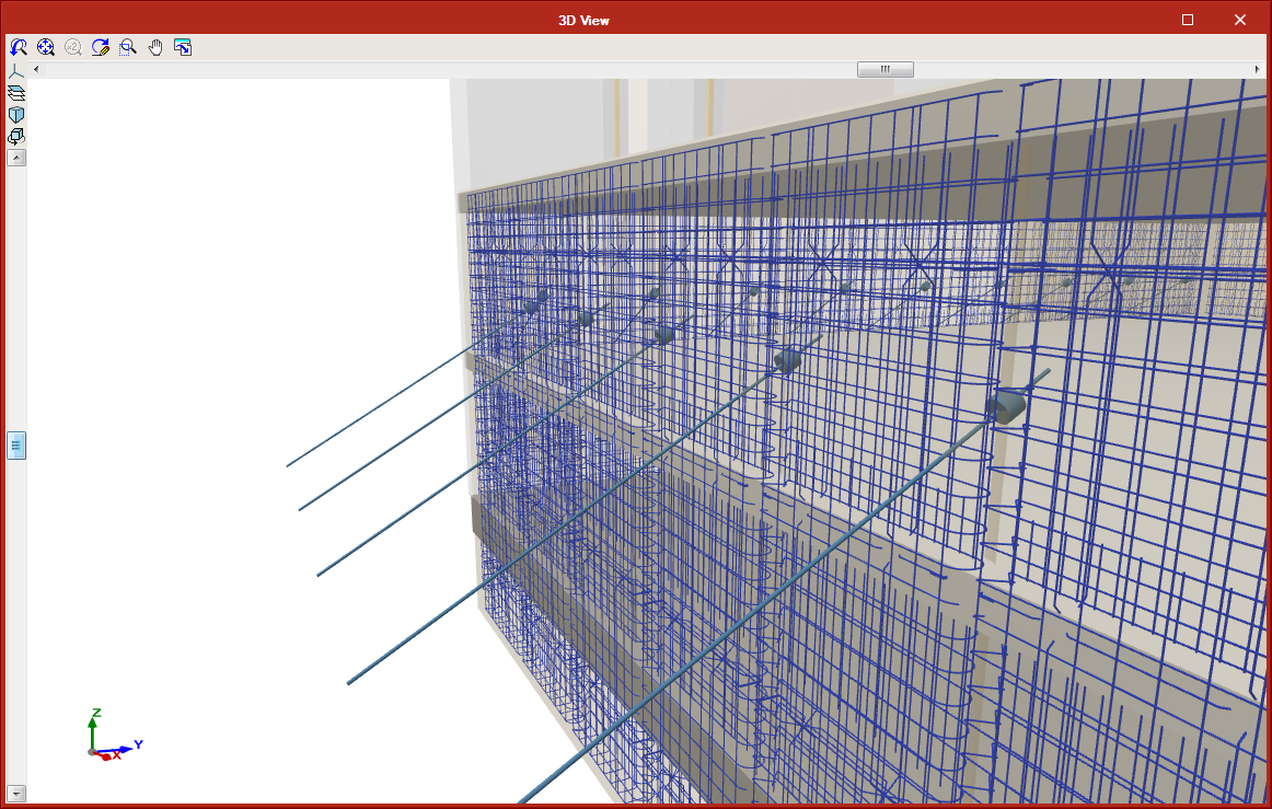
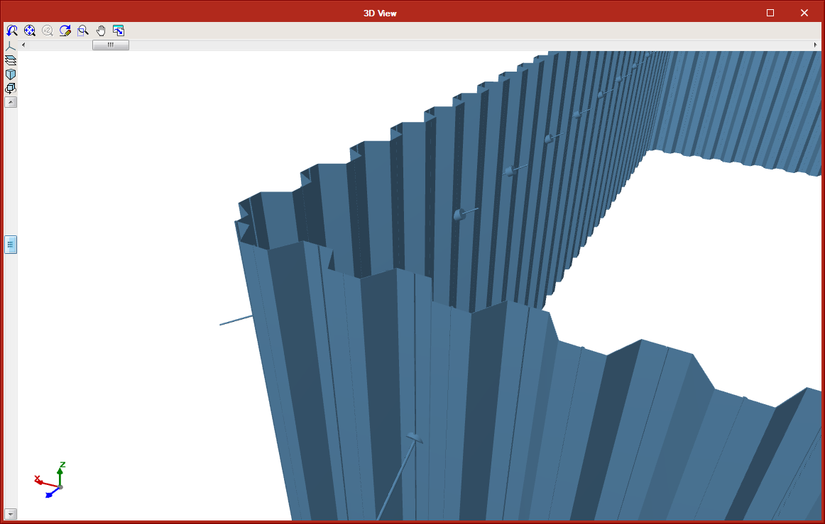
StruBIM Embedded Walls exports the anchors and elements that correspond to each type of wall (concrete volume, reinforcement, piles, mini piles or steel sheet pilings) to the BIM model.

More information will soon be available on the “StruBIM Embedded Walls” webpage.

View of the BIM model generated by CYPE Open BIM programs

As of the 2018.i version, CYPE programs integrated in the Open BIM workflow generate models with “GLTF” format (GL Transmission Format) that are exported to the BIMserver.center platform together with the corresponding “IFC” format file. The standard and open GLTF format, offers greater interoperability possibilities between applications dedicated to the generation and visualisation of 3D content. This way, CYPE joins other companies that have adapted the GLTF format such as Google, Microsoft, Adobe, Oculus and NVIDIA.

The generation of these models from CYPE applications allows users to have a direct view from the viewer that is integrated in the BIMserver.center web platform and in the application for mobile devices.

Interpreting the columns of the BIM model

Generating the columns of the BIM model

The 2018.i version of CYPECAD includes the automatic generation of concrete columns based on the columns of the BIM model. The program will generate a rectangular or circular concrete column of the same size and at the same position for each column that has been defined in the BIM model.

To do so, the assistant that is activated when a project is created from a BIM model, contains the new stage “Columns”. In this stage, users can select the columns that are to be generated depending on their material. The assistant generates the columns with the same reference they have in the BIM model or with an automatic reference. In this stage, users can also select the type of support (with or without external fixity) columns starting at the first level will have. Columns starting on higher floors will be generated without external fixity.

The fixed point of the column will also be generated in accordance with the fixed point of the column of the BIM model.

Updating the columns of the BIM model

When users decide to update the BIM model with the changes the architectural model may contain, any columns that have been generated previously will not be modified. Neither will their position be changed nor will they be deleted nor new columns added, even though these changes have occurred in the BIM model. What is updated is the template of the BIM model and it is up to users to decide what to do when a column has been moved, deleted or introduced, as this affects intersections with the beams, columns and floor slabs that have already been introduced in CYPECAD.

In the previous version (2018.h), the way CYPECAD acts when a column is added or an existing column is moved was modified. As of this version, CYPECAD does not automatically recreate column-beam intersections and users can choose to recreate the intersections manually or have the program recreate them automatically for a floor using the “Reload group” option.

New column (BIM)

To be able to introduce a column that interprets another column of the BIM model that was not present when the connection of the CYPECAD project to the BIM model was launched (after the first import), the tool, “New column (BIM)” has been implemented. When this option is selected, the outlines of all the columns of the BIM model will appear. Then, if we click on one of these outlines, a column will be generated with the same dimensions as the column of the BIM model on each floor.

Users must bear in mind that including a new column may interfere with beams that are already present in floors of the CYPECAD project. Nonetheless, how the program behaves, regarding the automatic adjustment of beams, when a new column is introduced or an existing one is moved, was modified in the previous version of CYPECAD (2018.h). As of that version, the program does not automatically recreate column-beam intersections. Users can recreate them manually or use the “Reload group” option (“Beam Definition” tab > “Groups” menu) to recreate them automatically in the current floor group.

Managing the templates of the BIM model

Since the possibility of connecting to a BIM model from CYPECAD was implemented in the 2018.c version, the program could obtain two types of templates from the BIM model:

  • The DXF or DWG templates associated with the BIM model. Furthermore, when a BIM project is launched from IFC Builder, users can automatically export a template in DXF format with the outline of each floor.
  • The templates of the “BIM model” that display the outlines of the floor slabs and outlines of the columns. These are updated when the BIM model is updated if the initial model has any changes.

The views of the DXF/DWG templates (including those IFC Builder may generate in the BIM model) can be managed from the “View selection” dialogue box.

As of the 2018.i version, another section appears in the same dialogue box in which users can also manage the templates of the BIM model. The templates of the BIM model will be shown in magenta when they are generated for the first time (validated outlines). When the BIM model is updated, new outlines or outlines that have undergone any changes will be displayed in cyan (Outlines not validated). In the “View selection” dialogue box, users can mark “Outlines not validated” outlines of the BIM model (cyan) as “Validated outlines” (magenta).

With this improvement, the outlines before the update can be clearly distinguished from the new outlines and so graphically appreciate the changes the architectural model has undergone.

Template visibility upon opening the project

The behaviour of the program when opening projects, regarding the visibility of templates in DXF or DWG format, or those of the BIM model, has been modified. In previous versions, when projects were loaded, the visibility of all the templates assigned to the “Column Definition” and “Beam Definition” templates was maintained. As of the 2018.i version, when a project is opened, this visibility is deactivated.

The reason for this change is because projects containing visible templates take longer to open, the time required being greater the larger the templates are and the larger the number of visible templates that are present. With this new behaviour, projects are loaded more quickly. Users can easily activate or deactivate the templates (DXF, DWG or BIM model) assigned to each floor or at the “Column Definition” tab by pressing the F4 key.

Grouping frames in frame drawings

An option has been included where users can indicate whether or not frames with the same geometry and reinforcement should be grouped in frame drawings (Frame drawings > Configure > General options).

In previous versions, the program always grouped frames with the same geometry and reinforcement.

Project comments

The possibility to add comments to the project has been implemented. The comments are managed in the “Job description” dialogue box (File > Job description).

The comments users add can be included in the Project report. This improvement allows, for example, users to manage a history of comments, modifications or revised versions of the project.

Project documents manager

The 2018.i version of CYPEPLUMBING Sanitary Systems (also the 2018.i version of CYPEPLUMBING Water Systems) includes a documents manager where users can view all the reports that are generated by the program. With this manager, users can create a document that includes selected reports, and then print it, export it to various format files (PDF, DOCX, Text, HTML, RTF) or attach it to the BIM project in PDF format (see the section on Export documents to the BIM project). The reports users can include in this document are organised in chapters with their indices and in the order they wish for them to be. It is also possible to configure the document headers and styles.

New reports (Design criteria, Checks and Materials)

The 2018.i version of CYPEPLUMBING Sanitary Systems includes three new reports that users can view and select to include in the project documents with the new Document manager (see previous section) together with the Results and Quantity reports that were already present in previous versions:

  • Design criteria
    Here users can specify all the design options corresponding to the selected code or customise the design options.
  • Checks
    In previous program versions, the program could generate a report of all the checks that have been carried out on the selected span (one by one). The checks report that is implemented in the 2018.i version gathers all the checks of all the spans.
  • Materials
    The materials report is created with the material catalogues that are used to design the project.

Configuration of the results and check reports

The “Results” report and the new “Checks” report can be configured.

Now, users can organise the information of the results report (by network, by floor, by criteria and/or by main span) and include the checks of the most important spans (main span and/or spans that fail checks), independently for the wastewater and rainwater networks.

Export documents to the BIM project

CYPEPLUMBING Sanitary Systems allows users to export the quantities of the project to the BIM model in FIEBDC-3 standard format (so it can be treated by bill of quantities programs such as Arquimedes) and the document configured by users using the Document manager (also implemented in this version) in PDF format.

Project documents manager

The 2018.i version of CYPEPLUMBING Water Systems (also the 2018.i version of CYPEPLUMBING Sanitary Systems) includes a documents manager where users can view all the reports that are generated by the program. With this manager, users can create a document that includes selected reports, and then print it, export it to various format files (PDF, DOCX, Text, HTML, RTF) or attach it to the BIM project in PDF format (see the section on Export documents to the BIM project). The reports users can include in this document are organised in chapters with their indices and in the order they wish for them to be. It is also possible to configure the document headers and styles.

Improvements in the design criteria report

Implemented in the design criteria report is the simultaneity information described in the design options defined by the selected code and by the possible technical customisation users can carry out.

New reports (Checks and Materials)

The 2018.i version of CYPEPLUMBING Water Systems includes two new reports that users can view and select to include in the project documents with the new Document manager (see project documents manager) together with the Design criteria, Results and Quantity reports that were already present in previous versions:

  • Checks
    In previous program versions, the program could generate a report of all the checks that have been carried out on the selected span (one by one). The checks report that is implemented in the 2018.i version gathers all the checks of all the spans.

    Additionally, the 2018.i version allows users to introduce customised descriptions in the checks report for each span and in general.
  • Materials
    The materials report is created with the material catalogues that are used to design the project.

Configuration of the results and check reports

As of the 2018.i version of CYPEPLUMBING Water Systems, the “Results” report and the new “Checks” report can be configured.

Now, users can organise the information of the results report (by network, by floor, by criteria and/or by main span) and include the checks of the most important spans (main span and/or spans that fail checks).

Export documents to the BIM project

CYPEPLUMBING Water Systems allows users to export the quantities of the project to the BIM model in FIEBDC-3 standard format (so it can be treated by bill of quantities programs such as Arquimedes) and the document configured by users using the Document manager (also implemented in this version) with PDF format.

Generation of vertical spans in the 3D view between elements introduced on the same floor but at different elevations

The program generates, in the 3D view, any vertical spans that join two elements introduced in the same floor but with different elevations. This already occurred as of the 2018.g version for consumption elements. These elements are introduced in the same floor plan as the pipe that feeds them. In the 3D view they appear joined by a vertical span without the need to have to manually introduce it.

Now, these vertical spans are also generated between pipes with different elevations or between other elements to which users assign a different elevation to that of the plane along which the pipe runs (connections, meters, tanks, pressure groups ...).

The vertical spans that are generated automatically by the program are drawn in the 3D view in a slightly lighter colour than the pipes and verticals spans introduced by users. The vertical spans that are generated will have the same diameter as the pipe from which they descend. If users wish to modify their diameter, the vertical span must be introduced manually using a vertical pipe.

In the attached image, the vertical spans that have been generated automatically are marked with a red circle (both in the 3D view and in the plan view).