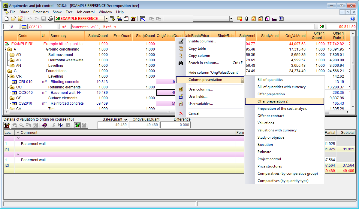
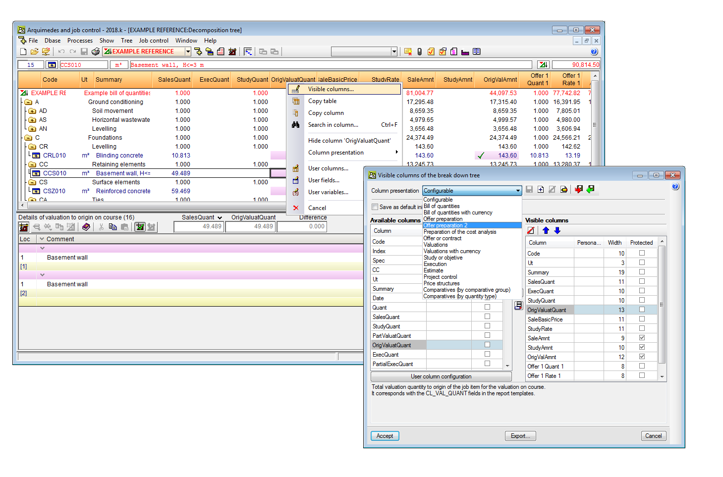
New features

2018.k Version

3 April 2018
Index

New features of the 2018.k version

CYPELEC Multiline (new program)

CYPELEC Multiline is a program designed to draw the multiline diagram of an electrical installation. This application is integrated in the Open BIM workflow using the IFC standard.

The program allows users to manually introduce the multiline diagram or generate it automatically using the information contained in an IFC file of the BIM model. With this second option, the single-line diagram that has been used to export the IFC must have the phase which each single-phase line is connected to.

The CYPE programs that can generate an IFC file with this information are:

CYPELEC REBT and CYPELEC NF can generate the multiline diagram of the installation themselves, however users cannot modify the diagram that is generated. With CYPE Multiline, users can obtain a proposal for a multiline diagram and edit it to carry out the modifications s/he desires.

To be able to use CYPELEC Multiline, the user license must include the “Multiline diagram” module permits.

CYPELEC Multiline is only available by downloading it from the BIMserver.center platform.

More information on CYPELEC Multiline will be available shortly.

Export data to BIMserver.center

3D viewer

Since the 3D view in “GLTF” format was implemented in the 2018.i version of programs that are integrated in the Open BIM workflow, 3D models can be viewed using the viewer that is integrated in the BIMserver.center web platform and using the application (App) for mobile devices.

As of the 2018.k version, the information that is exported to the 3D viewer of BIMserver.center is increased for the following CYPE programs:

Documents and drawings

As of the 2018.k version, the following CYPE programs incorporate more documents to BIM projects located in the BIMserver.center platform:

  • CYPELUX, CYPELUX CTE, CYPELUX RECS, CYPELUX LEED y CYPELUX HQE
    The drawings that are elaborated by these applications are exported as documents attached to the IFC file. More information can be found in the “Export drawings to the BIM project” section.


  • CYPELUX LEED y CYPELUX HQE
    The justification reports of each certification and the drawings of the project are exported. More information can be found in the “Export drawings and documents to the BIM project” section.

Generation of the 3D view of the Revit model in BIMserver.center

When the “Open BIM complement for Revit” exports the architectural model to the project located in the BIMserver.center platform, a “.GLTF” file is generated (as well as the IFC file), which allows users to view the 3D view of the REVIT project in the BIMserver.center platform, using the Web version and application (App) for mobile devices.

Access to “Wall forces” from the reinforcement editing window

As of the 2018.k version, users can consult the forces in walls in the “Edit reinforced concrete wall reinforcement” and “Edit block wall reinforcement” windows. To do so, both dialogue boxes include the new “Forces” button, which provides access to the force consultation dialogue box of the selected wall.

Block reinforced concrete wall reinforcement

The 2018.k version allows users to block the reinforcement of reinforced concrete walls. To do so, a new option has been implemented: “Block reinforced concrete wall reinforcement” in the “Beams/Walls” menu of the “Results” tab. This option opens a dialogue box in which users can assign a “Blocked reinforcement” or “Unblocked reinforcement” property to reinforced concrete walls. The reinforcement of walls that have been assigned the “Blocked reinforcement” property will not change during the design process.

Compatibility of the NTC 2017 (Mexico City) concrete code with the CF 2015 and CF 2008 earthquake codes of Mexico

As of the 2018.k version, if the selected concrete code is the “NTC 2017 (Mexico City)” code, the following earthquake codes of Mexico can be selected (as well as the NTC 2017 itself):

  • CFE 2015
    Manual de Diseño de Obras Civiles. Diseño por Sismo. Sección C: Estructuras. Tema 1: Criterios generals de análisis y diseño. Mexico 2015.
  • CFE 2008
    Manual de Diseño de Obras Civiles. Diseño por Sismo.

Short circuit currents

With the 2018.k version, the calculation of short circuit currents in accordance with the IEC 60909 international code is added to the calculation of load flows.

The “Short circuit” section has been created in the toolbar of the program, which includes all the options that allow users to configure and obtain the design results of the short circuit currents:

  •  Calculation of the short circuit current
  •  Analysis of the short circuit loadcases
  •  Results view
  •  Results report
  •  Design settings
  •  Checks
  •  Show/Hide results

Calculation of the short circuit current 

Calculates the initial symmetrical short circuit current in the electrical installation for the following short circuit types:

  • Three-phase short circuit current
  • Two-phase short circuit current
  • Two-phase earth connection short circuit current
  • Single-phase earth connection short circuit current

Analysis of short circuit loadcases 

With this option, a dialogue box opens where users can view, for each loadcase, two tables which display the design results of the short circuit currents (Results tab) and the short circuit check for switches (Protection tab).

  • Results tab
    Displays a table containing all the short circuit currents that have been calculated, by phase, maximum and minimum values.


  • Protection tab
    Shows a table that displays the switches that are contained in the installation and checks that the cut-off power of the switch is greater than the maximum short circuit current.

Results view 

This option opens a new toolbar that allows users to configure the view of the results on-screen. Users can choose to:

  • View the three-phase short circuit current, two-phase short circuit current, two-phase earth connection short circuit current or single-phase earth connection short circuit current, or all at once.
  • Select the desired short circuit phase.
  • Select the maximum or minimum short circuit currents.

Results report 

Displays a table containing the short circuit currents, with the maximum and minimum values for each bus displayed in bold. It should be noted that the type of short circuit that gives rise to the highest current depends on the direct sequence, inverse and homopolar short circuit impedance of the system.

Design settings 

This button opens a dialogue box containing 5 sections:

  • Voltage factor “c” to calculate the maximum and minimum short circuit currents
    Specified in this section are the values of voltage factor “c” of table 1 of the IEC 60909-0 code. These values can be modified and its value affects the calculation of the maximum and minimum short circuit currents.
  • Default impedance
    Users have the option to specify a default impedance value for cases where they consider that the short circuit is not clear (with null impedance).
  • Cut-off power in switches according to the IEC standard
    In this section, users can choose the cut-off power (serviceability or ultimate) that is compared with the maximum short circuit current, for the specific short circuit check of the switch.
  • Selection of loadcases to analyse
    Users can select the loadcases with which the short circuit can be calculated.
  • Selection of the elements to analyse
    The buses or relative positions of the cable for which the short circuit current is to be calculated can be selected here.

Checks 

This option displays a panel containing the short circuit checks that fail. One of these is the validity of the short circuit switches that have been installed.

Show/Hide results 

Shows or hides the short circuit results on-screen.

Short circuit currents at a relative position of the cable

A cable or transmission line that is situated between two buses. CYPELEC Networks calculates the short circuit currents in both buses, i.e. calculates the current at either end of the cable.

The program has an option that allows users to calculate short circuit currents at a relative position of the cable as well as at its ends. To do so, the “Short circuit at a relative distance of the cable” option must be activated and users have to indicate the relative position (between 0 and 1) where the short circuit occurs. After the analysis, the program will display the results of this short circuit next to the representation of the cable or transmission line.

Coverage contour map diagrams in BIMserver.center

When a project that has been designed using CYPETEL Wireless is exported to the project located in the “BIMserver.center” platform, the IFC file that is generated includes a “GLTF” file with the coverage contour maps in the 3D view. This allows users to view the diagram with the 3D viewer of “BIMserver.center” using the Web version or application for mobile devices (App).

This “GLTF” file is independent to that generated by CYPETEL Wireless with emitters, so each file can be viewed independently.

Radiation diagram and predefined antenna types

As of the 2018.k version, users can define the radiation gain and diagram of the emitter antenna, for each frequency band. The program also incorporates an assistant to help users to import the properties of different predefined types of antennas.

Equipment height control

The 2018.k version has incorporated checks to warn users of incorrectly defined heights for emitters and work planes with respect to the height of the space.

Design optimisation

The design process has been optimised and can now design several emitters simultaneously, thus considerably reducing the time required to perform the analysis.

Design options have been added, which allow users to define the influence emitters have on receivers on other floors, specifying the elements to be considered in the analysis.

Improvements in results reports

The information contained in the results reports, for each receiver point, has been redistributed for a better understanding of the calculations that have been carried out.

New example project

A new project called “Detached house” has been included, where users can view an example of a designed installation.

Design options and check

Users can now add a series of complementary checks that modify and complement the specific design options and checks of the selected code.

Since the program’s first version, the design options and checks of the selected code are defined in the “Design and check options to be carried out” section of “General settings”. In the 2018.k version, the “General checks” button has been added to the “Analysis and drawing options” section of the “General settings” dialogue box, which opens a panel with same name, that allows users to configure more design and check options:

  • General checks
    • Positioning of the traps in series
      By activating this option, users can check that these elements have not been placed in series.
    • Minimum free height
      The field “Minimum free height” has been included in the definition of each floor. By activating the “Minimum free height” option in the “General checks” dialogue box, the program will check that the lowest point of each pipe span of each floor does not exceed the minimum free height that has been defined.
  • Calculation options
    In this section of the “General checks” panel, users can create alternative options to those that have already been defined in “Design and check options to be carried out”. Several design option groups can be configured. Once defined, they will not be applied to the design of the installation until they have not been assigned by users using the “Design options” button of the “Project” section of the top tool menu.

DXF templates in drawings

The DXF/DWG templates that have been previously uploaded in the project can now be added to the drawings that are generated by the application. This option can be activated from the drawing configuration window.

Export drawings to the BIM project

Drawings that have been elaborated by the application can now be exported as documents attached to the IFC file that is generated by CYPELUX programs. This way, the drawings of the installation become a part of the BIM model.