New features

2019.g Version

4 April 2019
Index

New modules and programs

Open BIM Residential Furniture (new program)

Open BIM Residential Furniture is a free application that allows users to introduce a furniture layout proposal for residential projects.

"Open BIM Residential Furniture" is integrated in the Open BIM workflow using the IFC standard. The program can be downloaded from the BIMserver.center platform and installed in Catalan, English, French, Italian, Spanish or Portuguese.

"Open BIM Residential Furniture" has a catalogue with numerous furniture combinations for all rooms of residential buildings: beds, tables, worktops, shelves, chairs, sofas, extractor fans, refrigerators, stoves, microwaves and televisions, which users place in the 2D view of the floor that is being viewed.

The program provides the 3D representation of the furniture that has been introduced in the linked project and becomes visible in all the 3D views of the applications participating in the project.

It also notifies the "Open BIM Electrical Mechanisms" application so users of this program know that electrical outlets have to be placed in the vicinity of the electrical appliances.

Open BIM workflow

New requirements and errors

The applications included in the Open BIM workflow of the 2019.g version include new requirements and errors that are communicated between them.

  • Between “Open BIM Residential Furniture” and “Open BIM Electrical Mechanisms”
    Electrical outlets should be introduced near electrical appliances.


  • Between “CYPEFIRE CTE” and “IFC Builder”
    The horizontal and vertical dimensions of façade openings must be at least 0.80 m and 1.20 m respectively, and be located at a height, with respect to the floor, not exceeding 1.20 m, according to DB SI 5 Fire-fighter intervention - Section 2.

The requirements and errors that are currently implemented in the Open BIM workflow can be found in the “List of requirements and errors” section of the “Open BIM workflow requirements” webpage.

CYPECAD / CYPE 3D

Tekla® Structures export update

The export process to “Tekla® Structures” carried out by CYPECAD and CYPE 3D has been updated.

The 32-bit 2019.g version of CYPECAD and CYPE 3D continues to export to the same Tekla versions. In other words, it exports the analysed and designed structure to versions 12.0, 12.1, 13.0, 13.1, 14.0, 14.1, 15.0 SR1, 16.0, 17.0, 18.0, 19.0, 21.1 (32 bits) of “Tekla® Structures”.

The 64-bit 2019.g version of CYPECAD and CYPE 3D, exports the analysed and designed structure to versions 21.1 (64 bits), 2018, 2018i and 2019 of “Tekla® Structures”.

More information on the export to Tekla® Structures.

Open BIM Health and safety

Scaffolding

European scaffoldings can now be defined. The scaffolding is introduced by defining the number of spans, levels of each span and elements each module is composed of.

Fences

A tool to introduce fences easily has been implemented. When the “Fence” button is pressed, two options appear; “Simple introduction” and “Multiple introduction”. With the second option, users can introduce the fences along a previously defined polyline.

Guardrails

The 2019.g version also includes a tool to introduce guardrails more easily. It is available by selecting the “Multiple introduction” option of the “Guardrail” menu.

Import the topographic model

As of version 2019.g, users can import the topographic model of the terrain from the BIM project and interact with it. The elements that have been introduced will be placed at the detected elevation of the topographic model. Users can select whether or not the topography is to be visible.

For "CYPE Health and safety" to correctly interpret the topographic model, the program that generates the model of the terrain must do so in an "IFCSite" or "IFCGeographicalElement" type entity.

Assign construction phases

A tool has been implemented to assign a selection of elements to the constructions phases in which they are to present (Edit > Assign phases).

StruBIM Anchors ACI-318

Edit the anchorage plate and section

As of the 2019.g version, an interface panel has been dedicated to create and edit anchorage plates and metal sections. As far as the plate is concerned, any geometry composed of a polygonal can be introduced, for which, users introduce its points. For design purposes, the plate is considered rigid. It can be level with the concrete, on a mortar filling or suspended from the anchors. In this last case the program distinguishes whether the anchors have a washer and base nut in contact with the concrete or not.

Furthermore, as of this version, users can introduce the metal section that is to be joined to the plate. It can be an I-section, circular hollow section or rectangular hollow section.

Generic edit of the concrete element

A panel dedicated to the concrete element has been added. In it, users can edit its thickness, reinforcement, their minimum cover and distance from each edge to the geometric centre of the section.

Introduction of the forces of the section

As of this version, users can introduce the forces of the section instead of the forces of each anchor. The forces are those of the one-dimensional structural elements: axial, shear and bending moments in both directions and torsional moment.

In the case of plates level with the concrete element or on a layer of mortar, the program performs an iterative calculation, due to the non-linear behaviour of the materials, until the integration of the stresses in the section, given a deformation plane, coincides with the forces imposed by the metallic profile. The behaviour of the materials is as follows:

  • Anchors
    Stress diagram - linear tensile deformation, with a modulus of elasticity of 210 GPa and null in compression (it is assumed they provide no compression resistance).
  • Concrete and mortar
    Stress diagram - deformation with constant compression (AISC Steel Design Guide 1) with a value of 0.85fc (ACI 318-14 22.8.3.2) and null in tension.

When the plate is suspended from the anchors, the concrete does not contribute and the anchors behave linearly in tension and compression.

The option to introduce the forces in each anchor can be used by pressing the top selection buttons of that panel.

3D view of the connection

A 3D view has been added in the top right of the program interface. This view shows the section, plate, anchors, and concrete element. The properties of the 3D view are:

  • The view adapts to the geometry that is introduced of all the elements.
  • Regarding the anchors, the anchor that is selected in the input table for the anchor coordinates is highlighted.
  • The reinforcement in the concrete element can be viewed depending on whether it has been introduced or not. The position of the reinforcement depends on the cover.

Open BIM workflow

View plates and anchors in the BIM model

The plates and anchors that are generated in the program can be viewed in the BIM model view. The model view will regenerate and display the latest changes of the plates and anchors by pressing the "Redraw" button Redibujar Vista 3D located in the view panel itself. Furthermore, a new panel has been added in the lower part of the user interface to edit the position of the plate - anchors set in the context of the project.

Export to the BIM model

As of version 2019.g, the 3D view of the plate and anchors is exported to the BIM project via a GLTF file contained in the IFC file that is generated by the program. This IFC file will also contain the PDF file with the check reports, as was done in previous versions.

Improvements in ergonomics

A button has been added in the upper left part of the interface where users can obtain a report where they can consult all the checks of the designed plates. In the dialog that appears, users can select the plates that are to appear in the results report.

The design button has been divided into two buttons, one to design the selected plate and another to design all the plates. This is because, when the number of plates and the number of combinations is high, it may take some time to design them all.

A button has been added in the top right to be able to see the 3D view of the BIM model in a new pop-up window.

AcoubatBIM by CYPE

New magnitudes to evaluate indoor and outdoor sound

As of the 2019.g version, AcoubatBIM by CYPE broadens the available acoustic indices to evaluate indoor and outdoor airborne sound. The new indices are:

Magnitudes for outdoor airborne sound insulation

  • Global apparent sound reduction index (R’w)
  • Global, A-weighted, apparent sound reduction index A (R’A)
  • Global, A-weighted, apparent sound reduction index for dominant automobile or aircraft outdoor noise (R’Atr)

Magnitudes for indoor airborne sound insulation

  • Global, A-weighted, apparent sound reduction index (R’A)
  • Global, A-weighted, apparent sound reduction index for dominant automobile or aircraft outdoor noise (R’Atr)

All the sound indices that are available in the program can be consulted in the General data section of the “AcoubatBIM by CYPE” webpage.

Open BIM Electrical Mechanisms

Open BIM workflow

Requirement in Open BIM Electrical Mechanisms. Installation of electrical outlets

Programs such as Open BIM Residential Furniture (implemented in this version) allow users to introduce appliances (televisions, refrigerators, microwaves ...) that need an outlet in their vicinity. These programs generate a requirement in "Open BIM Electrical Mechanisms" so that users of this program take into account that they must introduce these outlets.

"Open BIM Electrical Mechanisms" reads the appliances using "IFC" files belonging to the connected Open BIM project, located on the BIMserver.center platform, if they have been previously included in programs such as Open BIM Residential Furniture.

New tools

New tools are included in the top menu.

Notes

The “Notes” block is included, which manages text tags, elevations or measurements.

Modify height position

Tool used to quickly modify the height of the elements that have been introduced.

This tool operates in a similar way as in other CYPE programs.

CYPELUX / CYPELUX EN

3D rotation of lights

As of the 2019.g version, CYPELUX allows users to rotate lights about their3 axes. This way, lights can be installed on the walls of the project and to direct projectors in a specific direction. The orientationcan be configured using the editing panel of the lights (indoor, outdoor and emergency), where users must indicate the rotation angle of the light on each of its axes:

  • Rx: Rotation angle of the light about its longitudinal axis, corresponding to the horizontal photometric plane of 0-180 degrees. Positive anti-clockwise when looking in the direction of the axis.
  • Ry: Rotation angle of the light about its transverse axis, corresponding to the horizontal photometric plane of 90-270 degrees. Positive anti-clockwise when looking in the direction of the axis.
  • Rz: Rotation angle of the light about its normal axis. Positive anti-clockwise when looking in the direction of the axis.

The rotations are applied in the following order: Rx, Ry and Rz.

Match rotation of lights

Now, the "Match" option, located in the "Edit" group of the toolbar, can be used to copy the orientation of one light to others. The corresponding values will be assigned to rotation angles Rx, Ry and Rz. This option was already available in previous versions of the application for "Height" and "Type of light” properties.

CYPEFIRE Sprinklers

Design of fire hose reels (FHR)

As of the 2019.g version, CYPEFIRE Sprinklers carries out an exhaustive analysis to design fire hose reels.

From the “General options” panel, users can access the data, which as of now, will be configured in the fire hose reel design:

  • Specific requirements for each space
    A section has been added to this panel for fire hose reel checks, where users can define the minimum pressure and flow checks.
  • Fire hose reel libraries
    When a new fire hose reel catalogue is defined, the hydraulic analysis is carried out using a fixed flow or by applying a discharge factor K.

Once the previous steps have been completed and the analysis has been carried out, the indicated checks can be seen for the fire hose reels.

CYPETHERM Improvements Plus

Consumption of primary energy

Primary energy consumption has been added within the performance indicators of the systems. This value is imported from IFC files generated by CYPETHERM programs with the EnergyPlus™ engine of version 2019.g or higher.

CYPETHERM EPlus

Multiple editing of project elements

A new tool has been implemented that allows users to edit the elements of the same type that have been defined in the project. It is a multiple editing tool and works with an assistant that starts by pressing the “Multiple edit” button located in the upper toolbar. The "Multiple precinct editing" button that appeared in previous versions has been integrated in this new tool.

The multiple editing assistant allows users to modify the properties of the zones, spaces, terminal units and of certain elements defined in the library, using the buttons at the top of the window. The assistant will only modify the properties chosen by users of the elements selected in the assistant itself (Elements that have been introduced-Zones, Spaces, and Terminal Units-, or Library elements- Spaces, Doors, Glazed openings, and Skylights).

The multiple editing assistant also allows users to delete zones and terminal units.

Open BIM workflow

Thermal envelope of the building in GLTF standard format

As of the 2019.g version, "CYPETHERM EPlus", "CYPETHERM HE Plus" and "CYPETHERM RECS Plus" export two independent GLTF files (attached to the IFC) with the thermal information of the building envelope to the BIM project located on the BIMserver.center platform. Each GLTF file allows users to view the data in a different way in any viewer that interprets the GLTF standard format (AUTODESK Viewer, glTF Viewer, BIMserver.center web viewer...):

  • Thermal model, by element
    The complete construction solutions used in the building are displayed, as well as their properties (reference, thickness and thermal resistance).
  • Thermal model, by layers
    The individual layers that make up each construction solution together with their properties (reference, thickness and thermal resistance) are displayed.

Export results to the Open BIM project

As of the 2019.g version, CYPETHERM programs with the EnergyPlus™ analysis engine (CYPETHERM EPlus, CYPETHERM HE Plus and CYPETHERM RECS Plus) can export the results reports they generate to the Open BIM project to which they are linked.

To do so, the Export button has been added in the "Results" tab. As with other programs included in the Open BIM workflow, this export generates a file with IFC format that is included in the BIM project, located on the BIMserver.center platform (other programs that also generate graphic documentation will include other "IFC" " in the project). The IFC files of CYPETHERM with the EnergyPlus™ analysis engine contains the PDF files corresponding to the results lists. These PDF files will be accessible from the BIMserver.center platform by any member of the BIM project team that has the appropriate role.

Import VRF equipment from Open BIM FUJITSU

As of the 2019.g version, CYPETHERM programs with the EnergyPlus™ engine (CYPETHERM EPlus, CYPETHERM HE Plus and CYPETHERM RECS Plus) can import the Fujitsu "VRF Airstage" equipment that have been defined in the Open BIM project using Open BIM FUJITSU.

Import data from Open BIM TOSHIBA

As of the 2019.g version, CYPETHERM programs with EnergyPlus™ engine (CYPETHERM EPlus, CYPETHERM HE Plus and CYPETHERM RECS Plus) import new data from the air conditioning systems defined in Open BIM TOSHIBA. Specifically, they import pipe lengths and the installation dimensions of the 1x1 split equipment with distribution by ducts, and the outlet water temperatures defined in the aerothermal equipment.

New CYPETHERM Eplus project examples

Two new example projects have been added:

  • Restaurant
    It consists of an isolated place for restaurant use whose room is air-conditioned using a compact roof unit that distributes the air through ducts.
  • Residential Row Houses
    Represents an urbanisation of residential homes, with individual heating, air conditioning and solar DHW installations.

Arquimedes

Configure decimals. Truncate

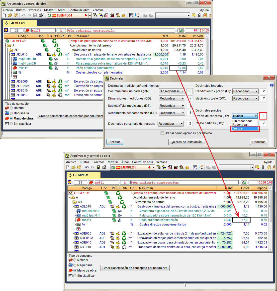
The possibility of truncating decimals of any of the magnitudes (prices, performances, amounts ...) that are defined in the "Decimals" dialogue box (Show menu> Settings> Decimals) has been implemented. Therefore, as of the 2019.g version, users can configure the decimals of each magnitude using the following options:

  • Not rounded
    Arquimedes works with all the decimals of the magnitude configured in this way.
  • Rounded
    configured this way are rounded to the indicated number of decimals.
  • Truncate
    Magnitudes configured this way are truncated with the indicated number of decimals.

Even though the following considerations already existed before the “Truncate” option was implemented in the decimals configuration, please recall that:

  • If a certification has been closed, it will not be possible to modify the configuration of the decimals corresponding to the quantity and certification tables.
  • Before modifying the decimal configuration, the program automatically copies the database so changes that imply the modification of the decimal configuration can be undone. The list of safety copies can be found in “Processes” > “Database copies list”.