Version 2025.d includes two new modules for checking and analysing piles (Piles II and Piles III) in CYPECAD, CYPE 3D and Foundation elements.
In the previous version 2025.c, the Piles I module was already implemented in the same programs. Therefore, as of version 2025.d, users of CYPECAD, CYPE 3D and Foundation elements have three pile modules that complement the design of deep foundations using pile caps. The three pile modules are the following:
- Piles I: Calculation of sinking load (v.2025.c)
This module, already implemented in the previous version (2025.c), is used to verify the bearing capacity of reinforced concrete piles under different loading conditions, taking into account the characteristics of the soil and of the pile itself. More information on this module can be found in the new features of version 2025.c.
In version 2025.d, the Piles I module includes a new feature in the pile sinking resistance analysis by allowing the selection of two analysis modes. More information on this can be found in the new feature of this version "Analysing the sinking resistance of piles using allowable bearing pressures".
- Piles II: Structural check (v.2025.d)
Implemented in this version (2025.d), Piles II offers the possibility to easily define the pile section and its reinforcement, and thus to check its resistance against the requesting forces transmitted by the pile cap to the pile head. More information on this module can be found in "Piles II: Structural check (new module)" in the new features of this version.

- Piles III: Lateral stability analysis (v.2025.d)
Also implemented in version 2025.d, Piles III incorporates the lateral stability analysis to facilitate the design of deep foundations subjected to significant lateral forces. This module can be used to carry out the checks of the "Piles II: Structural check" module (if it is included in your license) also considering the lateral forces transmitted by the pile cap to the head of the piles. The analysis is carried out using the OpenSees© analysis engine and is based on a finite element model where the behaviour of the ground is assimilated to a series of non-linear springs. More information on this module can be found in "Piles III: Lateral stability analysis (new module)" in the new features of this version.

To use this module, the following permissions are required in the license, depending on the program to be used:
- In CYPECAD
“CYPECAD”, “Pile caps” and the pile modules you wish to use. - In CYPE 3D
“CYPE 3D”, “Pile caps” and the pile modules you wish to use. - In Foundation elements
“Foundation elements” and the pile modules you wish to use.
In addition, in any of the three programs listed above, the user license must also have the "OpenSees©. Professional version" if the "Piles III: Lateral stability analysis" module is one of the modules being used.
As of version 2025.d, CYPEHVAC includes a new module that can analyse and design controlled mechanical ventilation (CMV) systems. The program includes all the elements required for this type of installation: ducts, heat recovery units, plenums, supply valves and exhaust valves, silencers, etc. from different manufacturers.
To use these features and others included in CYPEHVAC, the user license must have the appropriate permissions.
As of version 2025.d, the "Project selection" window in the apps connected to BIMserver.center incorporates a new notification system to inform users about the latest new features on the platform.
This space displays relevant messages about new features, enhancements and recommendations related to BIMserver.center. In addition, direct links to documents, tutorials and additional resources will be included to facilitate the adoption of these new features.

As of version 2025.d, when clicking the "Share" option of the apps (before starting the generation of the contribution files), a check is made to ensure that the user is part of the BIMserver.center project team. If the user does not have the appropriate permissions, a warning message is displayed. This prevents the generation of unnecessary files when the user does not have editing rights.

In version 2025.d, CYPE Architecture has new furniture elements grouped into two new sections: Accessibility and Waste.
- The "Accessibility" section contains the following: stair lifts, platform lifts, grab rails and shower chairs.
- The "Waste" section contains containers of different sizes, models and types (waste, organic, glass, paper and plastic).

As of version 2025.d, Open BIM Site can obtain maps via WMS services from the following data source:
- France
- Géoplateforme - WMS INSPIRE Raster.

As of version 2025.d, a new tool has been incorporated to automatically calculate the area of the nodes that make up the carpentry according to the number of leaves it is made up of.
This improvement will make it possible to obtain the thermal transmittance of the window and door frames in a simpler way, optimising their integration into the building's energy model.
The feature is available exclusively for manufactured carpentry, both for interior and exterior windows.
In version 2025.d, the ability to convert steel structures and 3D models integrated into native elements within the Revit environment has been added.

This feature can be used to import projects from CYPECAD or CYPE 3D that contain steel or composite structural components and their subsequent conversion to native Revit entities.

In this update, two new categories have been added to the Revit native entity converter: IfcPile and IfcMember, to extend and improve the classification and conversion of structural elements.

- IfcPile
Corresponds to deep foundation elements, specifically piles, which are topped by a pile cap. With this incorporation, these elements can be correctly identified within the IFC model and, subsequently, converted to native elements within Revit.

- IfcMember
Represents steel bar-type elements that are part of a structural assembly. With its implementation, these bars will be classified as column elements or beam elements, depending on their function within the structure, thus allowing their conversion to native elements without loss of information.

As well as the conversion of the structural elements "piles" themselves, in this 2025.d version, the possibility of converting the reinforcement of the piles into native entities within Revit has been incorporated.
This means that the reinforcement associated with these elements can be imported and recognised as native elements in the Revit model.

A new toolbar has been added to the plugin's main interface to improve the accessibility and organisation of the options. It is structured in two main sections: "Settings" and "Tools".

Settings
The configuration section brings together options for customisation, conversion control and IFC data management.
- IFC options
Defines specific configurations for the import and export of models in IFC format.


Tools
The tool section includes additional tools for viewing, filtering and managing structural models, making it easier to navigate and analyse BIM content.

- Applying transparencies to structural elements
Modifies the visibility of certain structural categories in the Revit model quickly and also applies them to the views of the user's choice, without the need to modify the visibility and graphics editor in the Revit interface.
- The categories that will be available for this tool are:
- Floors
- Walls
- Structural columns
- Structural frame
- Ramps
- Structural foundations
- Stairs
- The categories that will be available for this tool are:

- Assign colour filters to reinforcements
This tool can be used to assign colours to the rebars according to their diameter for the available views selected by the user without the need to create a filter for each one of them. The colours can be customised by the user, as well as the series of colours used in the original design program.

- Information on levels
This provides specific details on project levels, facilitating project analysis and organisation.

- Search instance
Facilitates the location of instances within the Revit project.

In version 2025.d, the CYPECAD, CYPE 3D and Foundation elements programs incorporate structural checking of reinforced concrete piles for deep foundations.
The new module "Piles II: Structural check" complements the design of this type of foundation, verifying the safety of piles as a structural element of reinforced concrete according to the criteria of the selected codes.
The program can be used to easily define the section of the piles and their reinforcement and to check their resistance to the forces transmitted by the pile cap to the pile head. If the lateral stability analysis is carried out, the stresses obtained from this analysis are also taken into account. The lateral stability analysis is part of the other pile module implemented in this version "Piles III: Lateral stability analysis".

In the "General data > Foundation elements with external fixity" panel, some options have been implemented that allow considering minimum values of the bending moment and axial force to be considered, as well as setting the buckling length of the pile for the calculation. These values can also be modified for each pile cap individually.

The verification has been implemented for the entire collection of codes available in the CYPECAD, CYPE 3D and Foundation elements programs.
To use this module, the following permissions are required in the license, depending on the program to be used:
- In CYPECAD
“CYPECAD”, “Pile caps” and “Piles II: Structural check”. - In CYPE 3D
“CYPE 3D”, “Pile caps” and “Piles II: Structural check”. - In Foundation elements
“Foundation elements” and “Piles II: Structural check”.
In version 2025.d, the CYPECAD, CYPE 3D and Foundation Elements programs incorporate the lateral stability analysis module to facilitate the design of deep foundations subjected to significant lateral forces.
This module complements the structural check of reinforced concrete piles (if your licence includes the "Piles II: Structural check" module), by allowing the checking of pile sections and reinforcements under various loading scenarios. For this purpose, the soil characteristics are integrated by means of p-y curves, and the non-linear behaviour of the soil is considered in the analysis.

The analysis is carried out using the OpenSees© analysis engine and is based on a finite element model where the behaviour of the soil is assimilated to a series of non-linear springs. The stiffnesses of these springs are determined according to the geotechnical parameters previously defined in the specifications of the soil layer.
The forces and displacements obtained at each point can be viewed on screen and exported to a CSV file. Furthermore, if your license includes the "Piles II: Structural check" module, the calculated forces are used to check the reinforcement of the pile section in accordance with the applicable codes.

To use this module, the following permissions are required in the license, depending on the program to be used:
- In CYPECAD
"CYPECAD", "Pile caps", "Piles III: Lateral stability analysis" and "OpenSees©. Professional version". - In CYPE 3D
"CYPE 3D", "Pile caps", "Piles III: Lateral stability analysis" and "OpenSees©. Professional version". - In Foundation elements
"Foundation elements", "Piles III: Lateral stability analysis" and "OpenSees©. Professional version".
Version 2025.d includes the option to select the calculation mode of the pile sinking resistance in the module "Piles I: Calculation of sinking load":
- By indicating the "Geotechnical parameters" (available since previous version -2025.c)
- By indicating the "Allowable bearing pressures"(implemented in version 2025.d)
This option is used to calculate the pile considering the allowable bearing pressures defined in the geotechnical study. This feature also introduces the possibility to include the effect of "negative friction" by entering negative values.
This selection is made in the "Advanced setup" dialogue box (Job menu > General data > "Foundation elements with external fixity" option > "Advanced settings" option).

In version 2025.c, the possibility of using precast concrete joist floor slab systems was implemented in CYPECAD. Now, in version 2025.d, the possibility of using joists with with lattice girders is implemented. A system or assembly is defined by the selection of a joist, a vault and the thickness of the compression layer. The selection of the precast elements is done by using the manufacturer's product catalogues that have been incorporated into the program.

The program designs the most suitable joist from those available for the selected assembly, as well as the reinforcement to be installed on site to comply with the safety requirements established by the standard. To this end, checks are carried out on the ultimate and serviceability limit states, as well as other geometric and quantity checks. To carry out the checks, the real section of the concrete is generated, both precast and poured on site, with its corresponding reinforcement.

The checks can be consulted and listed in detail, and any modification made by the user to the result proposed by the program will have an effect on the checks.
The floor systems are available for the concrete standards Structural Code and Eurocode 2 (including the various national annexes). In addition to the requirements of the concrete standard, the provisions of EN - 15037 have been considered, which complements the specifications for the particular case of precast joists.

CYPECAD version 2025.d includes the following program improvements and corrections for some specific cases:
- An error that occurred when consulting the node checks has been fixed. This error could occur in some cases after editing a frame from the checks panel.
- A systematic error that occurred when importing a CYPE 3D structure with aluminium sections as an integrated 3D structure has been fixed.
- The checking of bar spacing has been improved. Previously it was being done with the limitations of the EHE08 standard.
- An error that could occur in the "Check the geometry of the current group" option in the "Analysis" menu has been fixed. This error occurred if vertical loads had been defined on any column.
- Wind action according to ASCE 7-10. Correction in the gust factor analysis.
In the case of applying the wind action standard ASCE 7-10, the criteria for classifying a structure as rigid or flexible has been corrected for the purpose of analysing the gust factor according to 26.9. Up until now, the program classified a structure as rigid if it met the requirements for "Low-rise building" (section 26.2). From this version onwards, a structure is classified as rigid if it meets these requirements, or if the natural frequency of the structure is equal to or higher than 1Hz. - An error that could occur in the "Export in CSV format" when the value of the thousands separator symbol in the Windows configuration was a blank string has been fixed.
- An error that occurred systematically when consulting the "Critical perimeter" check on punching bolts if the selected standard is "Eurocode (Spain)" has been fixed.
- The import of integrated 3D structures from a CYPE 3D work has been improved. In some cases, the import was not allowed to be carried out because it was not correct to check that all the nodes with external links were at the same level.
- An error that occurred when designing columns has been fixed. This error occurred systematically if a concrete column with a rectangular or circular section had been defined, which started on a concrete column with a generic section.
- The "Deformed" option has been improved. The "View structure" check is now functional. This option was accidentally removed when making an upgrade in a previous patch.
- An error that used to occur when designing frames has been fixed. This could occur for beams with variable depth, whose upper plane was not horizontal.
- An error has been fixed in the "Transverse reinforcement > Match reinforcement spans" option in the portal frame editor. This error could sometimes occur when editing the "Layout" after selecting a span.
- An error that occurred in the fire resistance check of columns has been fixed. This error could occur in certain cases, when the µfi value was greater than 1.
- An error that could occur when checking concrete nodes has been fixed. This error could eventually occur in the case of having defined several steel beams connected to a concrete column during the process of analysing the job without obtaining the reinforcement.
- An error in the frame editor has been fixed. The functionality of the "Centre beam" check, which inadvertently stopped working in patch 2025.c due to changes related to hardware acceleration in the editor, has been restored.
- The import of jobs from BIMserver.center and those created from an IFC has been improved. In some cases, depending on the definition of the columns in the source program, the position and fixed point of some columns were not correctly interpreted.
- In CYPE 3D and CYPECAD the "Reports on a selection of elements" has been improved. The language can now be taken into account to obtain reports and drawings.
- The design of solid slabs and waffle slabs has been improved. Loads associated with user static earthquake loads can now be assigned.
- The drawing of joist lengths on screen and in drawings has been improved. Previously it was not displayed for joists with a length shorter than the length of the text.
- The "Drawing composition" with beam frame drawings has been improved. In some cases, after moving a frame, it was not displayed in the new position, even though the change of position had occurred.
- The inclined beam drawing has been improved. If "Quantities summary" has been selected, an empty box is no longer displayed when there is no concrete beam.
- The "Reinforcement ratios, per diameter", ‘Foundation element report", "Strip footing report" have been improved. Previously, if the selected concrete standard was ACI type, "Grade x" type steels were shown as "Grade x".
- The "Sloped floor slabs/El. Changes" panel has been improved. The colours for white wallpaper were always displayed, now the colours for the selected wallpaper are displayed.
- An error has been fixed in the "Punching shear" option. This error occurred when defining a panel delimited by two extended columns joined at their ends by beams, and this panel is inside another one.

- The search for references has been improved. The search for shear wall references was not being carried out.
- The creation of jobs from a CYPE 3D job has been improved. The library of aluminium sections is now imported.
- The fire checking of beams has been improved. Beams embedded in walls and crown beams are now checked.
- An error that occurred when inserting walls has been fixed. This error could occur when inserting a wall in an open job after having inserted walls with a defined pressure law.
- The drawing of beam axes in drawings has been improved. In some cases, with beams facing each other and depending on the angle between them, the axis of one of them could extend outside the plan.
- An error that could occur when editing the reinforcement of a portal frame, after having modified the width of a beam in contact with an abacus, has been fixed.
- The "Assign base reinforcement" option has been improved. In some cases, if there were floors with different edges on the same floor, it was not possible to assign a valid base reinforcement for the selected panel.
- An error in the generation of floor plans has been fixed. This error could occur if floor plans and beam portal plans are generated at the same time and the floor plans show anchor plate details. Instead of showing anchor plate details, some beam portal frames could be shown.
- The "Renumber" option in "Columns, shear walls and starts" has been improved. If the initial reference was P01, the next one generated was P2. In version 2025.d it is P02.
- The "Template object snaps" have been improved. There is now one selection for the "Column definition" tab and another selection for all other tabs. In addition, each time the program is opened, the last selections made are maintained.
- An error in the columns schedule drawing that could occur if the diameter of the abutment branches at the start was different from the diameter of the trusses has been fixed.
- An error that could occur when opening a job showing the message "(trv) != NULL" has been fixed. This error is due to an inconsistency in the data of the intersection of several beams. Now a message is displayed to redo the geometry at that intersection.
- The "Design options" panel that is displayed when designing a job has been improved. If none of the possible options can be activated, it is not displayed. This condition was not working correctly in the "Simplification of the design model" options.
- An error that occurred when defining a box has been fixed. The error occurred systematically if the assigned name was over eight characters long.
- An error that could occur in the modelling process of hollow core plates and composite slabs has been fixed. This error could occur when the side beams of these panels were almost parallel to the direction of the slabs, or mixed slabs.
- The beam portal editor has been improved. The "Centre on the beam" option had no effect. This started to happen in version 2025.b due to changes made to use hardware acceleration in this editor.
- The beam portal editor has been improved. When exiting the editor without making any changes, checks were not carried out. In version 2025.c, the checks were always carried out by mistake.
- An error that could occur when checking the forces of a column with beam connections at different heights in a floor has been fixed.
- The export of members from integrated 3D structures to IFC has been improved. They are now exported as beams or columns depending on their layout (in the same way as in the 3D view).
- The export of beams to IFC has been improved. If any of the "Beam numbering criteria" options are active, the beam reference is now exported considering the selected option.
- The display of contour plots has been improved. The colour of the texts is now determined according to the luminance of the background on which they are displayed, choosing between black or white to make them easier to read.
- An error that occurred when drawing foundation elements has been fixed. This error could happen occasionally due to tie beams or strap beams overlapping with other beams in a foundation element. Now, when this occurs, a warning is displayed when saving the floor plan.
- The drawing of the fixed point of columns in the layout plane has been improved. In the case of a column with a displacement and an angle other than 0, it was drawn without considering the rotation of the column.
- The beam portal frame editor has been improved. It is now possible to edit portal frames after the results of the job have been lost due to a change in the data entry. Some portal frames may not be editable as the data available for them is not consistent due to the changes made.
- The 3D view of piles has been improved. They are now displayed with their actual length.
- An error that could occur when opening a job, after having deleted a floor where "Parapet" type building elements had been defined, has been solved.
- The generation of bolts "At corners" has been improved. In some cases, in columns rotated by more than 45º, the bolts corresponding to one of the corners were not generated correctly.
- The column distortion report has been improved. If a column is exempt in a floor plan, a single span will be considered instead of two, which was previously the case.
- The design of waffle slabs has been improved. Previously, when a section needed to be reinforced with more than 255 bars of the maximum diameter, the program displayed a warning and did not continue with the design. Now, in this case, 255 bars of the maximum diameter are placed and it continues with the design of the rest of the elements. The bars that have been designed in this way are shown with the text "Insuf." In these cases, a "Reinforcement in slab area outside table range" warning is displayed in the final design report.
- The display of contour plots has been improved, allowing much faster drawing in some cases. This improvement is particularly noticeable when the selected colour range is discrete and the number of colours is large. In these circumstances, the display time used to be considerably longer, depending on the values displayed and the geometry of the elements, whereas now it is significantly faster.
- An error that occurred in the analysis when a ramp was not correctly defined has been fixed. In these cases, a warning is first issued and you are asked if you wish to continue.
- An error that could occur when obtaining beam portal frame quantities in certain cases, when a section of the portal frame corresponded to a beam under a floor slab and was in contact with both an opening and a floor slab, has been fixed.
- An error that occurred in the "Forces in columns, shear walls and walls" option when selecting a wall that starts at a higher level than the foundation level has been fixed.
- The detection of support elements at the ends of ramps and staircases has been improved. Previously, walls whose axis was not defined in the centre were not processed correctly.
- The editing of beam frames has been improved. When editing from the "Beam errors" option, the text of the stirrups was drawn twice in different positions, which prevented them from being displayed correctly.
- The splicing of the longitudinal reinforcement bars of columns has been improved when the "Splice at the centre zone of the span" option is active. Previously, it was done as shown in "1", and now with the improvement as shown in "2" (see image).

Certain seismic codes require the fulfilment of the minimum base shear condition when applying the modal-spectral dynamic method for the analysis of the seismic action.
As of version 2025.d, the possibility of activating this check, already implemented in previous versions of CYPECAD, is also available in CYPE 3D.
You can find more information by following the links below:
- Base shear correction for seismic design using the dynamic analysis method.
- Base shear condition verification. Results adjustment
(Base shear condition verification. Results adjustment - CYPE)


Until version 2025.d, the manufacturer section libraries were integrated directly into the program code.
As of version 2025.d, these section catalogues have been moved to the Open BIM Database.
This improvement makes it easier to incorporate catalogues from new manufacturers and allows for a more agile and efficient management of the updating and maintenance of existing catalogues.


As of CYPE 3D version 2025.d, the properties panel of the selected section includes information on its linear weight.

In the connection analysis model, one of the bars is set as the load-bearing element, unless a baseplate has been defined. The remaining bars are connected to this element, on which the loads are applied.
Up until version 2025.d, the bars connected to the load-bearing element had no external links, allowing users to define forces in the direction of each axis and moments around each axis.

This is the default model and the one used in previous versions. The end of the bar has no external links, allowing the six forces to be defined.
- N - Vy - Vz - Mx - My - Mz
This is the default model and the one used in previous versions. The end of the bar has no external links, allowing the six forces to be defined. - N - Vy - Mz
This model defines loads in the XY plane. The end of the bar is constrained for displacement in the z-axis and rotation in the y-axis. - N - Vz - My
This model defines loads in the XZ plane. The bar end is constrained for displacement in the y-axis and rotation in the z-axis. - N - Vy - Vz
In this model, the end of the bar is constrained for rotation and no moments can be inserted.
These new models are useful for dealing with different structural situations. For example:
Case 1
The hollow section bar is hinged in the structural model and connected by a single bolt. If the unrestrained model is used, an unstable mechanism can be generated (Case 1 - A). By changing the load model to N - Vy - Vz, the local model of the connection resembles the connection conditions in the global model of the structure (Case 1 - B).
Case 2
Two angles are connected, where one acts as a load-bearing element and the other receives a tension applied at the centre of gravity of the section. If the unrestrained model is used, the eccentricity between the load and the connection of the load-bearing section generates a penalising moment (Case 2 - A). By changing the loading model to N - Vy - Vz, a more balanced stress distribution between the two sections is achieved (Case 2 - B).
Case 3
The eccentricity of the diagonal bar generates a moment that penalises the haunch. In this case, the displacement out of the plane formed by the beam and the diagonal is constrained, so the local model of the connection is more similar to the global model by selecting the N - Vz - My model (Case 3 - B).

As of version 2025.d, connection reports can include images of the connections.
In the "Model" and "Analysis" tabs, the "Images" section has been added to the toolbar ribbon. This section offers a tool for snapping images, as well as a library for managing them.

By clicking on "Snap image", a snap of the 3D view is generated and saved in the image library. Users can assign a reference to it, which will be the text shown at the bottom of the image in the list. Furthermore, depending on the type of 3D view, the image has a specific type, which determines in which chapter of the report it will be included.
- Images snapped from the "Model" tab shall appear in the "Connection components" section.
- Snaps from the "Maximum demand capacity ratio" view shall be included in the "Checks" section.
- The screenshots of the contour plot result views of the "Stress/Strain" analysis shall be placed in the "Stress/Strain" section.
- Screenshots of the buckling results shall be placed in the "Buckling" section.

The size of the images in the report is set by default, although users can scale the images according to their needs.
As well as snaps of the 3D views, additional images can be added to the library. To do so, simply click on the "Add" icon in the list of images in the library.

In version 2025.d, a tool has been implemented to define the loads applied to each bar based on the mechanical properties of its section. In the load edition panel, on the force table for each bar, the wizard for modifying the forces of the selected load case appears.
This tool changes the table value of each force by the new value calculated from a user-defined factor, the mechanical properties of the bar section and the yield strength of the bar steel. The factor can be defined with a positive or negative sign. To the right of each force activated by the user, the calculated force is displayed. On the right side of the panel, the mechanical properties of the bar section are displayed.
This tool is useful, for example, when it becomes a requirement to design the connections with a higher strength than that of the connected bars, as mentioned in different seismic design regulations.

The index drawing of each bolt, anchor or timber fastener has been implemented in the 3D view of the connection.
The options to show or hide these indices are enabled under "View options".

As of version 2025.d, a small diagram with the layout of the bolts for each operation will be included in the section on the definition of the bolts in the summary report.

In version 2025.d, the import of the nodes defined in the structural model has been implemented.
This task can be carried out in the import of structures from CYPE 3D, ETABS® or SAP 2000®. A node will be created with the same reference as the node in the structural model and with the same bars.
In previous versions, geometric detection was carried out based on the ends of the bars.

Up until version 2025.d, the shear check of the bolts was carried out considering the worst-case scenario: the shear plane passing through the threaded zone of the thread.
As of version 2025.d, depending on the plates to be joined and the length of the shear plane, the program evaluates whether the cutting plane is on the threaded or non-threaded part of the thread.
When the thicknesses of the plates to be joined are different, the cutting plane may vary according to the direction in which the bolt is placed, passing through one area or the other. In these cases, the bolt shall be evaluated in both directions and, if in any of them the cutting plane passes through the threaded area, this condition shall be considered in the check.

The length of the shear plane is included in the bolt library. The series of bolts available in the program have been updated to incorporate this information. In projects created with previous versions, the bolt libraries will assign the threaded area a length equal to the length of the thread, as was previously the case.
The libraries can be updated via the library management to include the length of the shear plane. To do this, simply click on the blue arrow icon and select the series to be imported. If you have a customised user library, the same procedure must be followed to update the bolt libraries and then save the customised library again.

As of version 2025.d, the contour plot result views include a new option to show or hide the finite element mesh.

As of version 2025.d, the representation colours of the different elements are configurable.
This customisation is carried out from the "Project > Settings" menu, where the colours can be edited according to the user's preferences.
This feature is made even more relevant by the new tools, incorporated in this version, to include images in the connection reports.

Up until version 2025.d, when the Eurocode, its national annexes or the Spanish structural code "Código Estructural" were selected as the steel standard, the separation between the axis of a bolt and the plate edges of all bolts in an operation was verified.
However, from this version onwards, this verification shall not be carried out when the bolts are located inside a group of bolts.

It is now possible to select the type of steel for bolt layout checks.
This feature is available when using the Eurocode, its national annexes or the Spanish structural code "Código Estructural" as the steel standard.

As of version 2025.d of CYPE Connect, the import wizard incorporates a new step that selects the bars to be imported according to the assigned tags.
This option is available exclusively for models created in CYPE 3D.

In version 2025.d, CYPE Connect incorporates a new tool for analysing selected connections directly from the list of nodes.
In previous versions, the program could analyse selected connections, but this selection had to be made exclusively from the 3D view of the structure.
Now with this update, the tool, located at the top of the list of connections, can be used to select and analyse connections directly from the list.

In version 2025.d, it is now possible to import the grid from CYPE 3D into StruBIM Steel.

In StruBIM Steel version 2025.d, a new total element weight variable has been included so that it can be added to the assembly sheets.

Version 2025.d of StruBIM Shear Walls incorporates tools that allow for the automatic or manual generation of drawings of shear wall sections designed in the program, facilitating the graphical documents of designs.

Under "Generation options" the following can be defined:
- Sheet format
Defines the format of the generated sheets:- With the "Type" option, a template can be selected so that the sheet adopts the format associated with it.
- The "Empty" option manually defines the format of the sheet.
- Organisation
Determines the sheet group in which the generated sheets will be inserted. - Representation options
The following options are available:- Represent the sections with a detail for each segment:
This option allows users to choose between two representation modes. If the option is deactivated, the entire section is shown with all its reinforcement. If it is activated, a general diagram of the section is presented together with specific details for each segment. - Show total number of bars in edge elements:
When enabled, the reinforcement tags of the edge elements show the total number of vertical bars (e.g. 14 #10). When deactivated, the number of layers and the number of bars per layer is displayed (e.g. 2x7 #7). - Show bar length: Adds the length of the bars to the horizontal bar tags.
- Show lengths and separations with units.
- Scale divider for drawing sections.
- Scale divider for drawing segment details.
- Multiplying factor of the cross-section representation size of the bars.
- Represent the sections with a detail for each segment:
- Tags
- Includes reference to the wall in the title of the drawings.
- Includes reference to the wall in the title of the drawings.
- Symbols
Defines the symbols or abbreviations used in texts, notes and explanations that appear on tags.

By clicking on the "Sheets" icon in the "Documents"’ button group, users can access the sheets editor for the selected wall.
The first time you enter this section, the program asks the user if they want to automatically generate the predefined sheet composition. If the answer is yes, a sheet is created for each section of the wall. The representation of each sheet will depend on the configuration selected in "Generation options", being able to show a detailed drawing of the whole section or a general diagram with specific details for each segment.
The work environment of the sheet editor is similar to that of Open BIM Layout, details of which are available at the following link: https://info.cype.com/en/product/open-bim-layout/. This drawing editor is also integrated with other programs such as CYPE Connect and StruBIM Steel.
The automatic generation of the sheet drawings can be performed when accessing the "Sheets" section for the first time or from the "Predefined sheets" option. According to the settings established in "Generation options", the program generates the drawings of the sections together with the labels of the reinforcement.

Each reinforcement package of each segment is shown in the drawing with a tag. In addition, tags are included for the transverse reinforcement bars of the intersections, such as U-bars or L-bars if used.

As well as the drawings of wall sections, the 2025.d version also implements the drawings of coupling beams.
In this case, the program represents an elevation and a cross-section labelling the perimeter reinforcement of the beam and the diagonals for each beam.

As of version 2025.d, IFC Builder includes the "Annotations" group in the toolbar, providing new options to improve the model's graphical documents. This menu allows you to enter drawing elements such as text labels, dimensions and quantities.
Also, to ensure that the placement is accurate, the object snap and template object snap options can be used, ensuring that the annotations are correctly aligned with the components of the job.

In version 2025.d, the types of protective devices that can be selected from a manufacturer catalogue have been increased. These catalogues are available when the applied standard is REBT (Spain) or NF (France).
The list of protective devices with manufacturer selection is as follows:
- Modular circuit breaker.
- Moulded case circuit breaker.
- Modular differential switch.
- Modular circuit breaker and residual current circuit breaker.
- Modular MCB with modular differential block.
- Modular magneto-thermal circuit breaker with permanent overvoltage protector.
- Modular circuit breaker with permanent and transient overvoltage protector.
- Modular surge protector for transient overvoltages.
- Fuse and fuse holder.

As of version 2025.d, CYPE Lightning will be integrated into CYPELEC Distribution.
In the toolbar, a new group called "Lightning protection" is added, with the necessary elements for the design of a lightning protection system by means of an early streamer emission lightning conductor (ESE).
In addition, a receiver is added in the "Project" group of the toolbar called "Protection level" to specify the protection level assigned to the project and on which the lightning protection design depends.
Once the early streamer emission lightning conductor (ESE) has been inserted, the program displays the protected volume and checks whether the volume is sufficient according to the characteristics of the building.

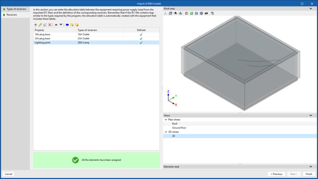
In the process of creating a new job in CYPELEC Distribution, and whenever there is a link to a BIM project, a wizard is launched for the mapping of electrical equipment from reading IFC files.
The wizard has two stages:
- The first stage creates or imports a list of electrical receivers.
- The second stage assigns the electrical equipment read from the IFC file to the types of receivers in the previously created list.
This assignment table streamlines the process for the subsequent design of the electrical system layout of the project.

Within the "General options" of the "Project" group in the CYPELEC Distribution toolbar, the possibility of modifying the "Prescription options" has been added.
With this option, the documents produced by the program (drawings, reports, quantities, etc.) can be configured, establishing the criteria for generating the descriptions of equipment, materials or services selected from the catalogues downloaded from the Open BIM Database and included in your project.

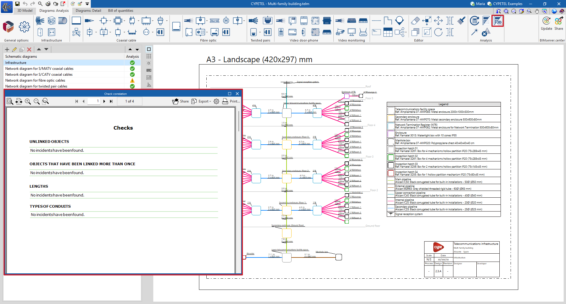
CYPETEL version 2025.d has a new "3D Model" tab. It includes the tools needed to define the spatial position of the elements in the telecommunications infrastructure (boxes, inspection hatches, sockets, conduits, etc.) in the BIM model using a 3D work environment.
As of version 2025.d, this tab will replace CYPETEL Systems. Information on the jobs carried out with this program can be read in CYPETEL.

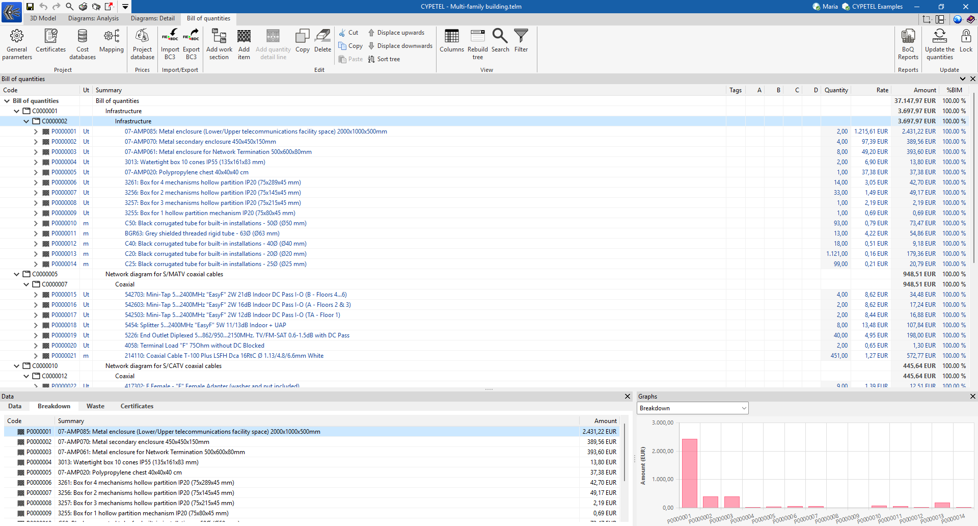
The "Bill of quantities" tab has been added to the CYPETEL toolbar.
In this tab, users have tools for generating and managing the bill of quantities of the installation analysed by the program. Here, the quantities can be extracted from the model and, based on this information, real items can be generated. This process is carried out by means of a correspondence system between the elements measured on the design model and the bill of quantity concepts (mapping).
To make it easier to enter construction prices, both complete databases and individual concepts can be imported from cost databases that have been developed according to the FIEBDC-3 standard (.bc3), such as the CYPE construction cost database.
Bill of quantity documents can be extracted in a number of templates (Quantities, Price justification, Budget, Bill of quantities, BoQ summary) exportable in HTML, DOCX, PDF, RTF and TXT format.
More information on the "Bill of quantities" tab in Open BIM project phase applications.
The "Check correlation" option can be used to detect issues related to the consistency between the design made in the "3D Model" tab and the elements entered in the diagram. This tool makes it easier to detect incidents in objects that have not been linked or that have been linked more than once, lengths, and types of conduits. This feature helps to complete the system diagram, detect duplicates and update conduit lengths to ensure correlation with the 3D model.
This feature is an adaptation of the "Check correlation" tool in the "BIM model" group, existing in previous versions, which was based on the contribution from the CYPETEL Systems program.
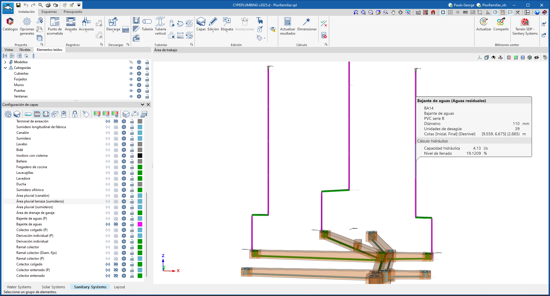
As of CYPEPLUMBING version 2025.d, elements such as consumption, downloads, fittings, which until now were entered directly from the upper toolbar, are now organised in floating menus that can be docked in the "Work area".
It is even possible to move them to another monitor, when working with several monitors, which facilitates their accessibility and visibility.

Furthermore, all buttons for graphical displays, which were located in the top toolbar, are now available in the side window "Layer settings".

As of version 2025.d, there is a third layer configuration (By criteria) for the elements in the system, in addition to the two that already existed in previous versions. The "Layer configuration" window is now organised as follows:
- By network (Type of pipe/Type of drainage)
Up until now it was only possible to activate or deactivate some of the networks, and from version 2025.d onwards the same options will be available as for the rest of the categories. - By own elements
- By criteria (General options)
This new configuration ensures greater control both when entering the system and in the respective analysis of the entry made and the design.
All configurations now have the same options: to lock snaps, whether or not to display symbols or 3D and to control the opacity of the 3D, and the new possibility to select a display colour in the "Work area" for each of the elements. The latter makes it easier to highlight the areas to be studied.
The "Filter" tool has been added to the light selection panel. Thanks to this new feature, the available lights can now be filtered according to the following parameters:
- Lamp. Lamp reference.
- Luminous flux. Option to set minimum and maximum values.
- Total power. Option to set minimum and maximum values.
- Efficiency. Option to set minimum and maximum values.
- Temperature. Option to set minimum and maximum values.
- Ra. Option to set minimum and maximum values.
- Length. Option to set minimum and maximum values.
- Width. Option to set minimum and maximum values.
- Diameter. Option to set minimum and maximum values.
- Height. Option to set minimum and maximum values.
- Bill of quantities. Option to display only lights that contain enough information to generate the bill of quantities.
This improvement streamlines the light selection process, allowing specialists to quickly find products that meet the technical specifications of the project.

For version 2025.d of CYPEFIRE Hydraulic Systems, the manufacturer catalogues for seismic bracing have been included and the analysis and checking of the bracing has been improved.
Some of the improvements to the analysis that have been incorporated are as follows:
- Detection of the start and end of collectors for entering the corresponding bracing.
- Detection of the start and end of uprights for entering the corresponding bracing.
- Analysis of the distribution of the bracings along the pipes.
- Detection of non-earthquake-protected sections of the system.

As of version 2025.d, the design tool has been optimised to allow partial design of the model to be carried out in addition to the total design that has been carried out up to now.
In the selection window, the type of design desired is defined; for a partial design, once the panel has been accepted, a control point must be selected. The design will be carried out from that point downstream.

In version 2025.d, another new element for the hydraulic analysis has been added: the wet riser outlet.
This new element functions in the same way as a sprinkler, fire hydrant or emitter, and is connected at any point of the system and is assigned to the desired analysis hypotheses to obtain the flow rate and pressure resulting from the analysis.
To enter these elements, the equipment included in the Open BIM Database can be downloaded. In version 2025.d, the wet riser outlets are considered as design elements, like the emitters, for which no standard check is carried out.
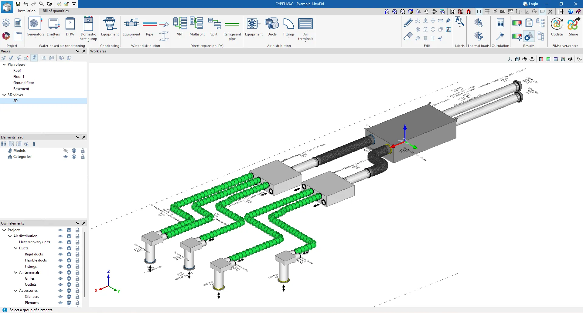
As of version 2025.d, CYPEHVAC includes a new module that can analyse and design controlled mechanical ventilation (CMV) systems. The program includes all the elements required for this type of installation: ducts, heat recovery units, plenums, supply valves and exhaust valves, silencers, etc. from different manufacturers.
To use these features and others included in CYPEHVAC, the user license must have the appropriate permissions.
In CYPEHVAC version 2025.d, it is now possible to insert end pieces in duct systems. These elements are used by some manufacturers where plenums and silencers do not have mouths for circular cross-section ducts, as they allow different connection systems to be made.
Therefore, depending on the end pieces used, the same plenum box or silencer can be connected to more or less circular ducts, as well as to ducts with a different section.
From the "Catalogue management" option, the manufacturer's catalogues for the end pieces that have been implemented can be downloaded. These can be used by the user in the system via the "End pieces" option in the "Equipment" section of the "Air distribution" group.

It is now possible to insert manufacturer duct connections in CYPEHVAC version 2025.d.
Up until now, the connections available in the program referred to ASHRAE connections with their design data and it was the application that drew the connection based on the input data.
As of this version, it is possible to enter the connections of prefabricated ducts supplied by the manufacturers. Just as it was already done for ASHRAE connections, the application can automatically generate the manufacturer's connections required for the installation of ducts without the need for the user to enter them manually. From the "Catalogue management" option, different manufacturer's connection catalogues can be downloaded.

As of version 2025.d, the air distribution system can be designed by selecting the alignment point of the ducts and their connections.
Up until this version, CYPEHVAC only allowed the duct axis to be entered as a reference so that its dimensions and all the necessary connections took this reference to modify its size and position.
From now on, users can select as a reference not only the axis, but also any of the vertices of its section and even the centre of any of its faces.

In version 2025.b, the air terminals available in CYPEHVAC were extended with the addition of supply and exhaust valves. These elements, which are mainly used in controlled mechanical ventilation (CMV) systems, could be selected regardless of the available connectors and flow regulators for each air terminal model.
In the new 2025.d version, the possibility of entering supply valves and exhaust valves has been included, considering the selection of the connector and/or flow regulator compatible with the valve model, as long as the catalogue of the selected manufacturer provides this information.
The insertion of supply valves and exhaust valves has not been modified, so users can still incorporate these elements into the system from the "Connectors" option in the "Air distribution" section, which are available once a manufacturer's catalogue has been downloaded via the "Catalogue management" option.
If a catalogue is chosen which includes the connectors and flow regulators compatible with the nozzles, a panel will appear where users can choose the connector and/or flow regulator they want to use with that model of valve.

In version 2025.d, CYPEHVAC incorporates a new feature that can be used to obtain all the documents generated by the program with neutral elements (in cases where it is not possible to work with user library elements). To this end, within the "General options" menu, in the "Results output" section, the prescription options have been implemented which can configure the documents produced by the program (drawings, reports, quantities, etc.), establishing the criteria for generating the descriptions of equipment, materials or services selected from the catalogues downloaded from the Open BIM Database and included in the project.
The following options are available:
- Commercial prescription of the selected product
- Prescription with possibility of equivalent product
- Description without specification of the commercial product

In CYPEHVAC version 2025.d, new options have been added to the graphical analysis of duct-specific results. As a result, it is now possible to display the most unfavourable route, the results of the air flow rates or the original colour of the materials used, for the air distribution system.
In addition, its behaviour has been changed, and a button has been added to activate the display of the analysis and to configure the analysis options.

Just like in CYPERTHERM LOADS, the full capabilities of IFC Builder have been integrated into the programs with the EnergyPlus™ analysis engine (CYPETHERM EPlus) in version 2025.d.
Now, when a new job is created with the program, there are two options for defining the thermal model: the first one consists of generating the thermal model from the creation of the 3D model of the building in the program itself, and the second one consists of importing the thermal model from the project.
- Creation of the 3D model
When this option is selected, the "3D Model" tab is enabled at the bottom left, leaving the application with the "3D Model" and "Energy simulation" tabs. This new tab, "3D Model", represents the total integration of IFC Builder in the program, and allows the creation of a geometric model with the simplified definition or by construction system of the different building elements, as it incorporates the Open BIM Construction Systems database.
In addition, the analytical geometric model required in the "Energy simulation" tab is generated from this tab. - Importing the thermal model from the project
If this option is selected when creating the job and linking it to the project, the operation of the program is equivalent to that of previous versions, i.e. the thermal model is imported from the project and the user cannot interact with the geometry of the model. In fact, the program does not show the "3D Model" tab and the users can only work on the imported thermal model.
By selecting this option, models from IFC Builder and Open BIM Analytical Model can still be read.

It should be noted that once the desired option for defining the thermal model of the building has been selected, it will not be possible to change this selection when updating the BIM model.
A job must be created with the new option selected to change this.

In addition to the updated interface needed for the integration of IFC Builder in this version 2025.d, the following changes have been made:
- New look and features of the "Building" tab
Work can be carried out on the 3D model of the building, so that elements can be selected on it, without having to locate them on the diagram in the tree.
The work on the building definition tree has also been improved by creating a more dynamic system of libraries. Although the library system of the building elements has been modified and the new types are not compatible with previous versions of the program, it is possible to import types created with previous versions of the program.

- New location and features of the "Drawings" tab
The position of the "Drawings" tab in the program has been changed. Additionally, it is now possible to create and edit the drawings of the thermal envelope with a wider range of tools and possibilities.

In version 2025.d, the "Catalogue management" option has been added to the toolbar, where the catalogues of the manufacturers of building elements, air-conditioning systems and DHW systems available in the Open BIM Database can be downloaded.
With this new management of manufacturer products, the number of manufacturers and products available for program analysis has been expanded.

In version 2025.d of Arquimedes and Arquimedes and Job control, users can now zoom into template editing by pressing the "Ctrl" key while moving the mouse's scroll wheel.
This action can be used to increase and decrease the size of objects and texts in the record areas, making it easier to edit templates.
Three new options have also been added to the top toolbar.
- The first button "Zoom (-)" is used to decrease the size of the objects in the work area.
- The second button restores the default zoom state and displays the current and the percentage to be recovered (100%).
- The third button "Zoom (+)" is used to increase the size of the objects in the working area.

Another change this new feature has introduced is that the position of the icon that indicates whether a "Zone" has a "Script before printing" and a "Script after printing" has been modified. Now, the icons appear right at the beginning of the "Zone". The first part in dark grey is the "Section" and the part in light grey is the "Zone".

The following countries and their federal entities or provinces have been added to the geographic and economic data of "Phase I. Preliminary analysis":
- Benin
- Burkina Faso
- Madagascar
- Mauritius

In version 2025.c of Open BIM Quantities, the adaptation of the Malaysian Standard Method of Measurement for Building Works (SMM2) was initiated in order to transform this standard into a set of measurement rules to facilitate the creation of bill of quantities for Malaysia. In version 2025.d, the adaptation is continued by incorporating more sections of the standard:
E Piling and Diaphragm Walling
- Piling
- Diaphragm walls
H Underpinning
- Generally
- Work in all trades
J Masonry
- Generally
- Dressed natural stonework
- Natural stone rubble work
- Cast stonework
- Clayware work
- Sundries
- Centering
K Waterproofing and Asphalt work
- Generally
The new features of this version 2025.d are completed with the incorporation of new concepts in the cost databases and the updated set of measurement rules (both referred to as "Malaysia - SMM2").
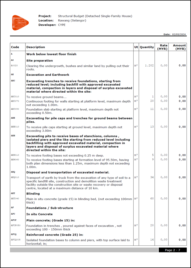
Please note that the cost database is accessed from the "Cost databases" option and the set of rules is accessed from the "Set of measurement rules" option. The cost database contains unclassified and unpriced items, with the items organised according to the work section and sub-work section criteria normally followed in Malaysian bills of quantities. A cost database allows users to assign items to the quantity criteria they consider, in this case, the set of rules has been created for Malaysia, in order to transform the data contained in the elements or components of a BIM model into items.
The application includes the tools needed to adapt the bill of quantity report documents to the format and style used in Malaysian bill of quantities.


The list with the sections of the standard included up to version 2025.d is as follows:
A General Rules
B Preliminaries
- Preliminaries particulars
- Contract
- Works, goods and materials by others
- General facilities and obligations
- Contingencies
C Demolition
- Generally
D Excavation and Earthwork
- Generally
- Site preparation
- Excavation
- Earthwork support
- Disposal of water
- Disposal of excavated material
- Filling
E Piling and Diaphragm Walling
- Piling
- Diaphragm walls
F Concrete Work
- In-situ concrete
- Formwork
- Precast concrete
- Composite construction
- Hollow-block suspended construction
- Prestressed concrete work
G Brickwork and Blockwork
- Generally
- Brickwork
- Brick facework
- Brickwork in connection with boilens
- Blockwork
- Damp-proof courses
- Sundries
H Underpinning
- Generally
- Work in all trades
J Masonry
- Generally
- Dressed natural stonework
- Natural stone rubble work
- Cast stonework
- Clayware work
- Sundries
- Centering
K Waterproofing and Asphalt work
- Generally