Earthquake-resistant systems in accordance with ANSI/AISC 341-10
CYPE 3D allows the main specifications and requirements related to the three most common earthquake-resistant systems defined in the American standard AISC 341-10 (Seismic Provisions for Structural Steel Buildings) to be included in the design of rolled and reinforced steel structural elements:
- Moment-resisting frames
- Concentrically braced frames
- Eccentrically braced frames
Also implemented is the analysis, design and check of Prequalified Connections in accordance with the ANSI/AISC 358-10 and ANSI/AISC 341-10 codes. The design and check of Prequalified Connections are described in detail in the section on “Prequalified connections in accordance with ANSI/AISC 358-10 and ANSI/AISC 341-10” of this webpage. These connections are applied to earthquake-resistant systems composed of “Moment-resisting frames”.
Moment-resisting frames
Unbraced frames or moment-resisting frames are an assembly of straight beams and columns connected to one another with welds, bolts or both. The bars making up these frames are mainly exposed to bending moments and shear forces that control their design.
The specifications of AISC 341-10 consider three types of moment-resisting frames in accordance with the grade of ductile behaviour considered in the design. The fundamental difference between them is that they are designed with different energy dissipation levels:
- OMF – Ordinary Moment Frames (AISC 341-10, E1)
- IMF – Intermediate Moment Frames (AISC 341-10, E2)
- SMF – Special Moment Frames (AISC 341 -10, E3)
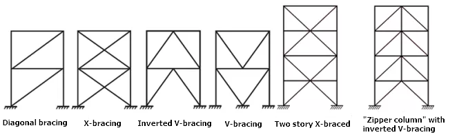
Concentrically braced frames
This type of structure is characterised because the central axes of the component structural elements are cut at a point, forming a grid-like structure. This is why lateral loads mainly induce axial forces in the bars of the braced frame.
The specifications of AISC 341-10 consider two categories for concentrically braced frames depending on the expected performance level:
- OCBF – Ordinary Concentrically Braced Frames (AISC 341-10, F1)
- SCBF – Special Concentrically Braced Frames (AISC 341-10, F2)
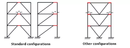
Eccentrically braced frames
In eccentrically braced frames, axial forces induced in the braces are transferred via shear forces and moments in segments of a reduced length (e), called links, where energy, due to creep of the steel, is dissipated. The links represent "structural fuses", which should be detailed adequately to avoid local buckling and other instability phenomena from degrading the response.
The specifications of AISC 341-10 consider a single category of frames with eccentric bracing:
- EBF – Eccentrically braced frames (AISC 341-10, F3)
Assigning earthquake-resistant systems in CYPE 3D
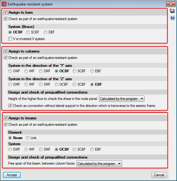
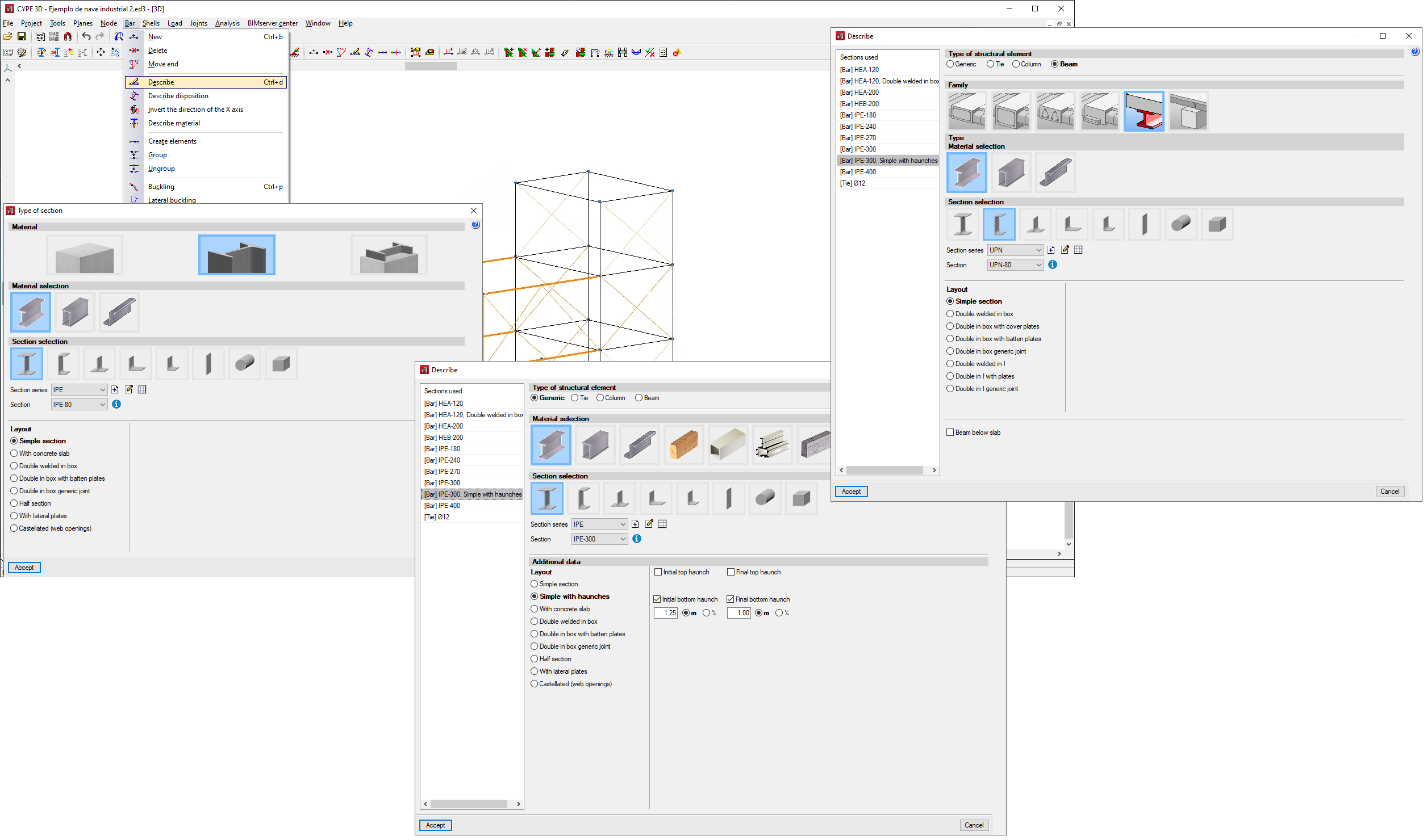
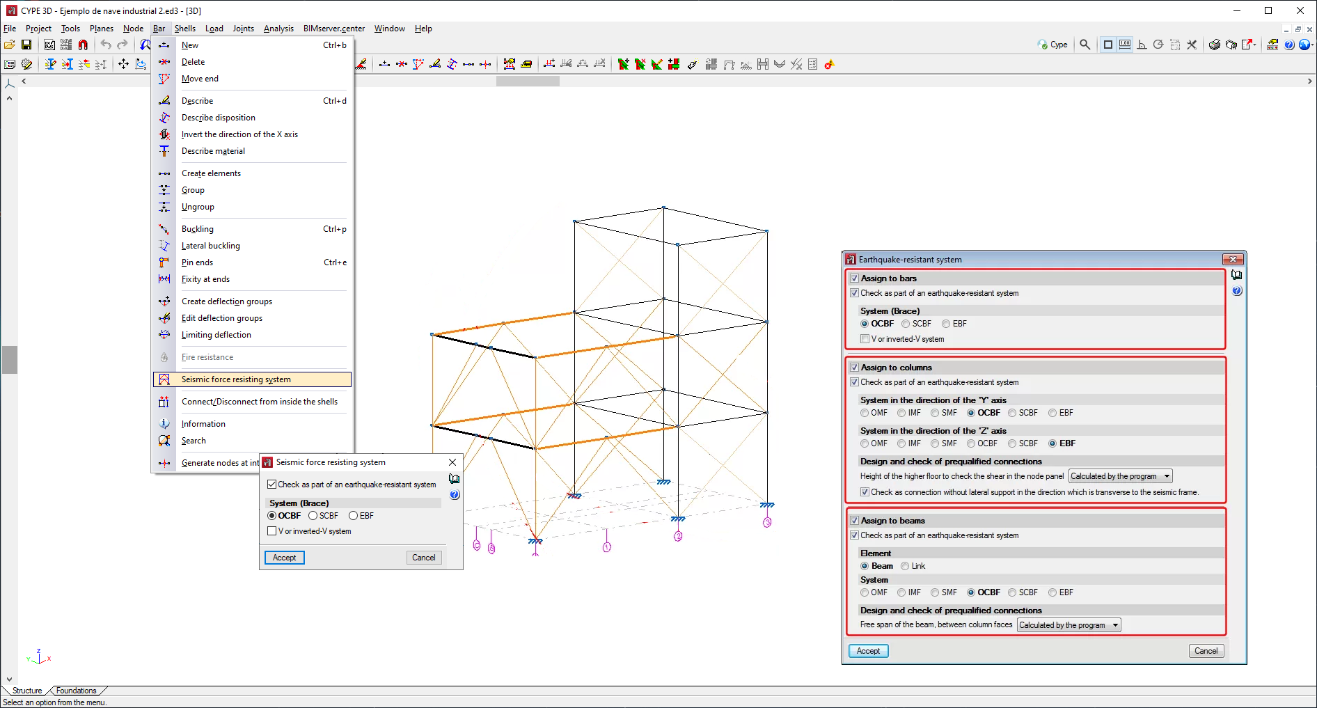
Users can assign earthquake-resistant properties to a bar using the “Seismic force resisting system” option in the “Bar” menu. This option is only available if the rolled steel code is ANSI/AISC 360-10.
Users can freely assign earthquake-resistant properties to bars in accordance with their own criteria. Naturally, it should be coherent with the geometry of the frame.
Bars assigned earthquake-resistant systems must be rolled or welded steel bars and be defined as Generic bars, Columns or Beams. These can be selected individually or multiple bars can be selected using the crossing method.
- Generic structural elements (bracing)
Generic-type bars are those that will be used as bracing, so, users can only assign OCBF, SCBF or EBF systems to them. - Column-type structural elements
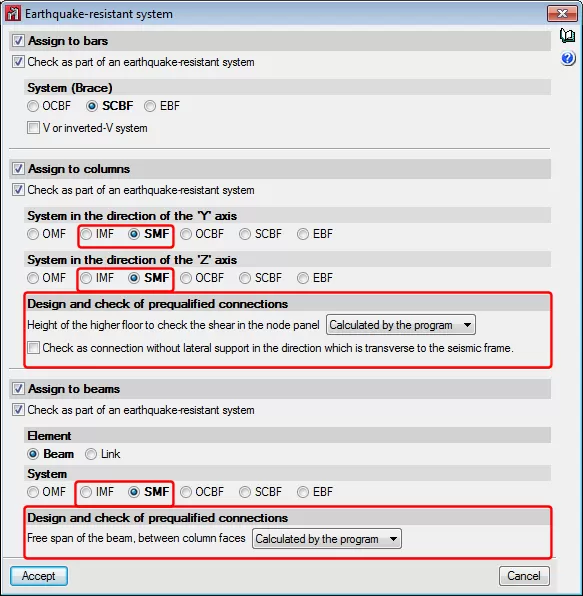
Any of the indicated earthquake-resistant systems (OMF, IMF, SMF, OCBF, SCBF or EBF) can be assigned to column-type bars in the direction of the local “Y” and “Z” axes. The earthquake-resistant system can be different in either direction.
When checking prequalified connections and if the selected earthquake-resistant system is IMF or SMF, it is possible to indicate if the “Height of the higher floor to check the shear in the node panel” is calculated by the program or if it is indicated by users. It is also possible to activate the option: “Check as connection without lateral support in the direction of the seismic frame”, which is applicable to connections of SMF-type frames. More information on these two options can be found in the sub-section: “Operation in CYPE 3D” (included in the section: “Prequalified connections in accordance with ANSI/AISC 358-10 and ANSI/AISC 341-10”). - Beam-type structural elements
Beam-type bars can be assigned any of the indicated earthquake-resistant systems (OMF, IMF, SMF, OCBF, SCBF or EBF) if the “Beam” option is selected as the “Element”. If users select the “Link” option as the “Element”, no type of system will be available to be assigned, because “Links” correspond to EBF earthquake-resistant systems, which is the type that is assigned automatically.
When checking prequalified connections, if the “Beam” option is selected as the “Element”, users can mark if the “Free span of the beam, between column faces” is to be calculated by the program or defined by users. More information on these two options can be found in the sub-section: “Operation in CYPE 3D” (including the section: “Prequalified connections in accordance with ANSI/AISC 358-10 and ANSI/AISC 341-10”).
Checks carried out
The additional checks CYPE 3D carries out on columns, beams and bracings that users classify as earthquake-resistant systems are detailed below.
Requirement of tensile strength and compression strength in columns
In columns, for all earthquake-resistant systems, the compressive and tensile strength is checked without considering the shear and bending moments and for special seismic load combinations, i.e. those in which the seismic action is amplified by the coefficient of over-resistance (Ωo) associated with the system.
Checks on moment-resisting portal frames
- OMF - Ordinary Moment Frames (AISC 341-10, E1)
- Analysis requirements
The columns are designed according to the tensile and compressive strength requirement specified in AISC 341 -10, D1.4a(2).
- Analysis requirements
- IMF - Intermediate Moment Frames (AISC 341-10, E2)
Checks carried out:
- Analysis requirements
The columns are designed according to the tensile and compressive strength requirement specified in AISC 341 -10, D1.4a(2). - Lateral Support on Beams (AISC 341-10, E2.4a)
The beams must comply with the condition of moderate ductility sections, according to section D1.2a of AISC Standard 341-10. This involves the control of lateral torsional buckling. - Members. Basic requirements (AISC 341-10, E2.5a)
Beams and columns must comply with the condition of moderate ductility sections, according to section D1.1 of AISC Standard 341-10. This involves the control of local buckling.
- Analysis requirements
- SMF - Special Moment Frames (AISC 341-10, E3)
Checks carried out:
- Analysis requirements
The columns are designed according to the tensile and compressive strength requirements, specified in AISC 341 -10, D1.4a (2). - Lateral Support on Beams (AISC 341-10, E3.4b)
The beams must comply with the condition of high ductility sections, according to section D1.2b of AISC Standard 341-10. This involves the control of lateral torsional buckling. - Members. Basic requirements (AISC 341-10, E3.5a)
Beams and columns must comply with the condition of high ductility sections, according to section D1.1 of AISC Standard 341-10. This involves the control of local buckling.
- Analysis requirements
Checks on concentrically braced portal frames
This type of structure is characterised by the fact that the central axes of the component structural elements intersect at one point, thus forming a lattice structure. This is why lateral loads mainly induce axial forces in the bars of the braced portal frame.
The AISC 341-10 specifications consider two categories of concentrically braced frames depending on the expected level of performance. CYPE 3D performs the following checks for each of these types:
- OCBF - Ordinary Concentrically Braced Frames (AISC 341-10, F1 (2)
- Analysis requirements
The columns are designed according to the tensile and compressive strength requirement specified in AISC 341 -10, D1.4a. - Slenderness in braces (AISC 341-10, F1.5b)
Bracing assigned to "V" or "inverted V" type systems must comply with the slenderness ratio:
- Analysis requirements
- SCBF - Special Concentrically Braced Frames (AISC 341-10, F2)
- Analysis requirements (AISC 341-10, F2.3)
Columns and beams are designed for special seismic load combinations, i.e. those in which the seismic action is amplified by the coefficient of over-resistance (Ωo) associated with the system. These combinations are automatically generated by the program. - Lateral Support on Beams (AISC 341-10, F2.4b)
The beams must comply with the condition of moderate ductility sections, according to section D1.2a of AISC Standard 341-10. This involves the control of lateral torsional buckling. - Members. Basic requirements (AISC 341-10, F2.5a)
Columns and bracing must comply with the condition of high ductility sections, according to section D1.1 of AISC Standard 341-10. Beams must comply with the condition of moderate ductility sections, in accordance with section D1.1 of AISC Standard 341-10. This implies control of local buckling. - Slenderness in braces (AISC 341-10, F1.5b)
Bracing assigned to "V" or "inverted V" type systems must comply with the slenderness ratio:
- Analysis requirements (AISC 341-10, F2.3)
Checks on eccentrically braced portal frames
In eccentrically braced frames, the axial forces induced in the braces are transferred by shear and bending forces in segments of reduced length (e), called links, where energy is dissipated by the creep of the steel. The links represent "structural fuses", which must be properly detailed to prevent local buckling and other instability phenomena from degrading the performance.
The AISC 341-10 specifications consider a single category of eccentrically braced frames. CYPE 3D performs the following checks:
- Eccentrically Braced Frames (EBF) (AISC 341-10, F3)
- Analysis requirements (AISC 341-10, F3.3)
Columns, bracings and beams (outside the link) are designed for special seismic load combinations, i.e. those in which the seismic action is amplified by the coefficient of over-resistance (Ωo) associated with the system. These combinations are automatically generated by the program. - Members. Basic requirements (AISC 341-10, F3.5a)
Columns must comply with the condition of high ductility sections, according to section D1.1 of AISC Standard 341-10. Bracing and beams (outside the link) must comply with the condition of moderate ductility sections, in accordance with section D1.1 of AISC Standard 341-10. This implies control of local buckling. - Members. Basic requirements (AISC 341-10, F3.5b)
The links must comply with the condition of high ductility sections, according to section D1.1 of AISC Standard 341-10. This involves the control of local buckling. - Link section limitations (AISC 341-10, F3.5b (1))
The link section must comply with the section limits specified in AISC 341-10, F3.5b (1). - Shear strength of the link (AISC 341-10, F3.5b (2))
The shear strength in the link is designed to comply with the most unfavourable of the following limit states: shear plastic capacity in the web and flexural plastic capacity for the complete section. - Link length (AISC 341-10, F3.5b(3))
The length of the link must comply with the limits in AISC 341-10, F3.5b (3).
- Analysis requirements (AISC 341-10, F3.3)
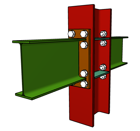
Prequalified connections in accordance with ANSI/AISC 358-10 and ANSI/AISC 341-10
As of the 2018.a version, CYPE 3D includes the analysis, design and check of prequalified connections in accordance with ANSI/AISC 358-10 (Prequalified Connections for Special and Intermediate Steel Moment Frames for Seismic Applications) and ANSI/AISC 341-10 (Seismic Provisions for Structural Steel Buildings).
Prequalified connections are applied to Special Moment Frames (SMF) and Intermediate Moment Frames (IMF) as specified in the ANSI/AISC 341-10 code.
Prequalified connections can be defined in projects where the rolled and welded steel code: ANSI/AISC 360-10, has been selected.
Implemented prequalified connections
The prequalified connections that have been implemented in the program are:
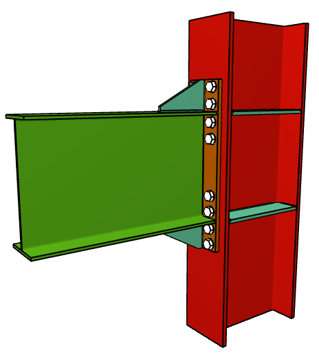
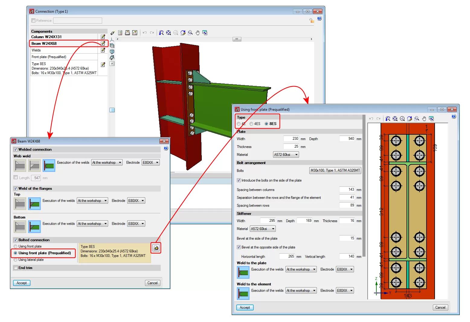
- 4E four-bolt unstiffened

- 4ES four-bolt stiffened

- 8ES eight-bolt stiffened

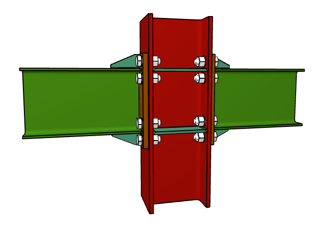
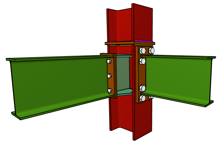
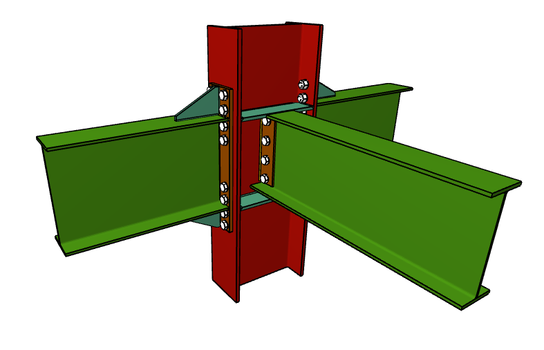
Nodes with interaction of several beams
Column-beam prequalified connections can be part of a node interacting with connections of other beams that may or may not be prequalified connections. For example:
- Prequalified 4E connection to the flange of the column and moment connection to the web of the column and ordinary front plate.
- Prequalified 8E connections to the flanges of the column and pilled connection using lateral plate to the web of the column.
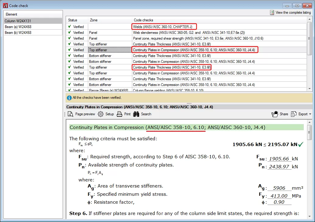
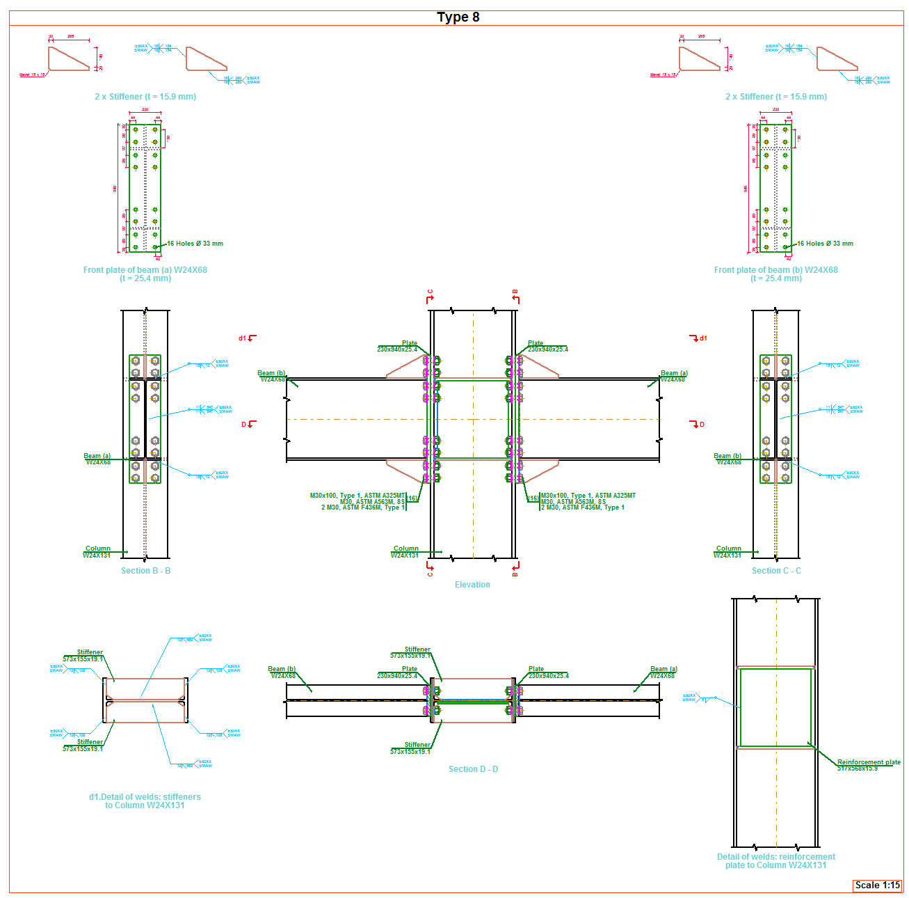
Checks and drawings
As well as the checks carried out on the connection in accordance with the ANSI/AISC 360-10 rolled steel code, specific checks of the ANSI/AISC 341-10 and ANSI/AISC 358-10 codes are carried out. The check report displays the chapter of the code that covers each check.

Operation in CYPE 3D
For CYPE 3D to carry out the analysis, design and check of prequalified connections of columns and beams, the following conditions must be met:
- The rolled steel code must be ANSI/AISC 360-10
- The bars reaching the node must be column-type and beam-type
- The earthquake-resistant system assigned to the bars reaching the node must be that of Special Moment Frames (SMF) or Intermediate Moment Frames (IMF).
When the type of earthquake-resistant system is assigned to columns and beams, it is also possible to:
- Define the height of the higher floor to check the shear in the node panel
This parameter can be calculated by the program or established by users. It is used to calculate the shear of the column above that would affect the check of the shear in the node panel. - Check as connection without lateral support in the direction of the seismic frame
Users can choose whether or not to carry out this option depending on the bracing there may be in the elements of the connection. This check is only carried out for SMF frames. - Free span of the beam, between column faces
Value required to calculate the moment at the face of the column, this value can be calculated by the program or provided by users.