Beam entry
To enter beams in CYPECAD, open the "Beam input" tab and move to the required group using "Move up group", "Go to group" and "Move down group".
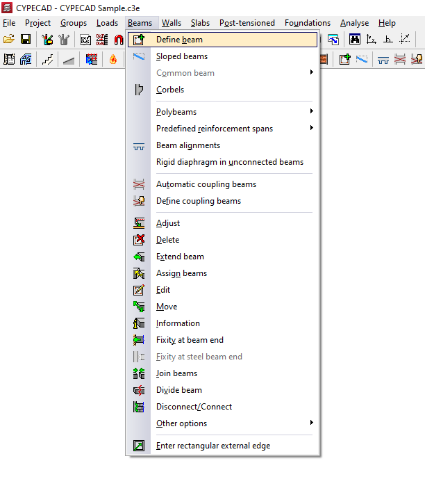
Then, in the "Beams" menu, select "Enter beam".
Selection of the current beam
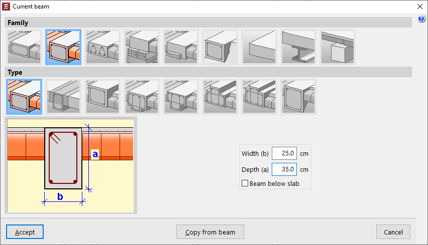
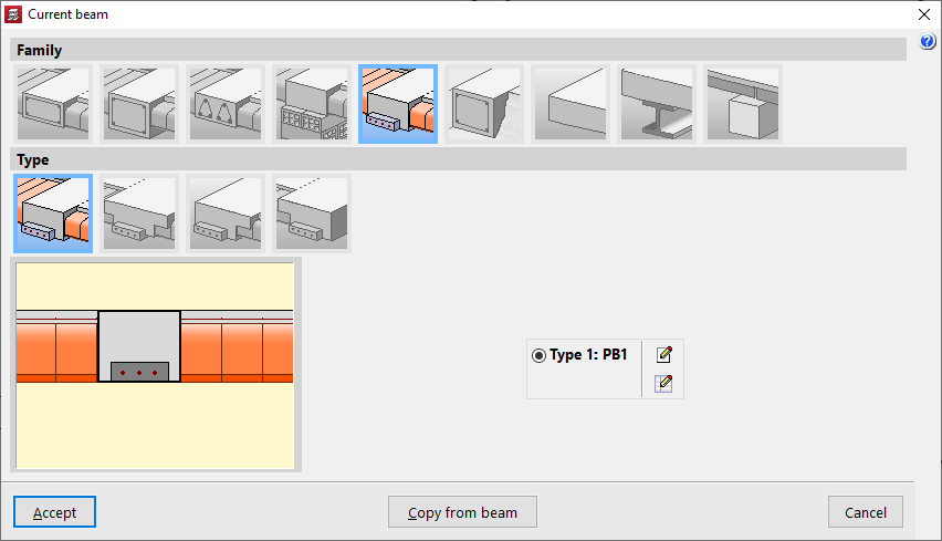
The program displays the "Current beam" window, where you can define the "Family" and "Type" of the beam to be entered, as well as its dimensions and properties.
The available families include:
- Flat beams
- Downstand beams
- Truss beams
- Beams with external restraint
- Prestressed beams
- Foundation beams
- Non-structural ring beam or boundary
- Steel beams
- Timber beams
All the values described above can be taken from an existing beam by clicking "Copy from beam" and then selecting another beam in the project with its information already defined.
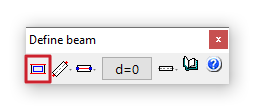
You can also access this window later by clicking the first option in the dialog box that appears while entering the beam, "Selection of the current beam".
Selection of the beam entry mode
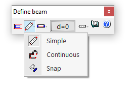
After confirming the beam type selection, choose the "Selection of the beam entry mode" from the drop-down list.
- "Simple" mode allows you to enter beam spans one by one by clicking on the start or end point.
- "Continuous" mode allows you to enter a sequence of beam spans through successive clicks. To finish, right-click and select "Finish entry". You can also "Delete last point" or "Delete all".
- "Snap" mode automatically converts a polyline or line from a DXF or DWG template into a series of CYPECAD beams by clicking on it. Depending on the pointer position, the beam is entered centred on or offset to one side of the selected line.
In the first two modes, you can use automatic snapping to previously entered columns and beams, as well as the "Template snaps" available from the corresponding button on the top toolbar.
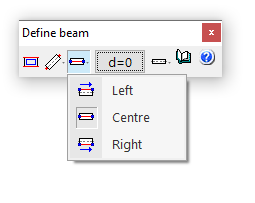
Selection of the alignment
The "Selection of the alignment" button allows you to specify whether the beam is placed at the "Centre", "Left" or "Right" of the entered line.
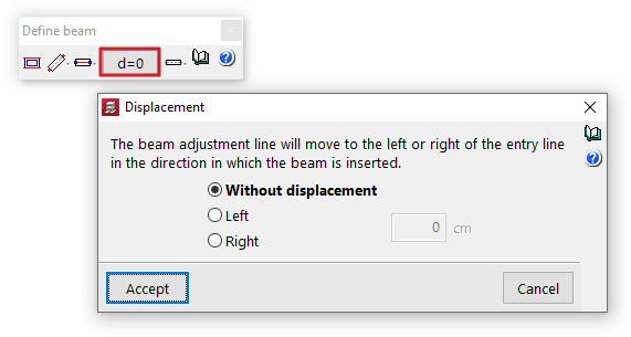
Displacement
The "Displacement" option allows you, during beam entry, to shift the alignment line by a specified distance to the left or right of the entry line, always in the direction of beam insertion.
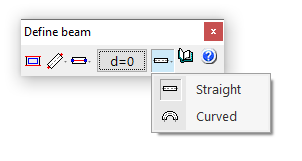
Straight and curved beam spans
The "Entry mode" option allows you to enter straight beam spans ("Straight") or "Curved" spans to model curved beams. In the latter case, in addition to the start and end points of the span, you must click a point along the arc to define the curved segment.
Beam layout in plan
Once the beam definition is complete, click "Accept". At this point, depending on the selected entry mode, you can move the pointer over other elements such as columns and beams to snap to them. You can also use snaps to previously entered templates.
Beam selection
To access the beam selection panel in CYPECAD, go to the "Beam input" tab. Then, from the "Beams" menu, select the "Enter beam" option to display the "Current beam" window. If you need to access this window later, you can click on "Current beam selection" in the dialogue box that appears while entering the beam, or use the "Edit" option from the "Beams" menu.
This way, the program allows you to specify the "Family" and "Type" of the beam to be inserted, as well as its dimensions and characteristics.
The available beam families are described below.
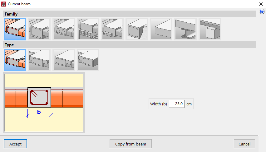
Flat beams
"Flat beams" are those that have the same depth as the floor slab. The following types of flat beams are available:
- Rectangular flat beam
- Flat T-beam
- Flat beam with right-hand flange
- Flat beam with left-hand flange
Flat beams will automatically take the value of the depth of the panel in which they are located. Therefore, the programme only asks for the definition of its "Width (b)". If the beam is located between two panels with different depths, it will take the greater of the two. If it is located between two panels at different levels, the depth of the beam will increase to cover the difference in height.
Hanging beams
"Hanging beams" have a different edge to the floor slab. The following types of hanging beams are available:
- Rectangular suspended beam
You must specify its "Width (b)" and its "Depth (a)". If the "Beam under floor slab" box is checked, the upper face of the beam is aligned with the lower face of the floor slab. If it remains unchecked, it will be aligned with the upper face of the floor slab.
- Rectangular suspended beam with composite head
In this case, the length of the "Left flange (i)" and the "Right flange (d)" of the concrete section that will work in conjunction with the beam must also be indicated.
- Inverted rectangular beam
This type of beam keeps the lower face aligned with the lower face of the slab and places the edge above it.
- Hanging T-beam
- Hanging T-beam with head embedded in the slab
- Viga en 'T' invertida con cabeza embebida en el forjado
- Inverted T-beam
The T-beam options, whether suspended, inverted or with the head embedded in the slab, allow the definition of a reinforced section with this shape, using the options "Width (b)", "Edge (a)", "Left flange (i)", "Right flange (d)" and "Flange edge (s)" options where necessary.
- Rectangular suspended beam with variable section
This option allows you to define a beam with a variable section with a specific "Width (b)" and an "Initial depth (a)" that may be different from the "Final depth (c)".

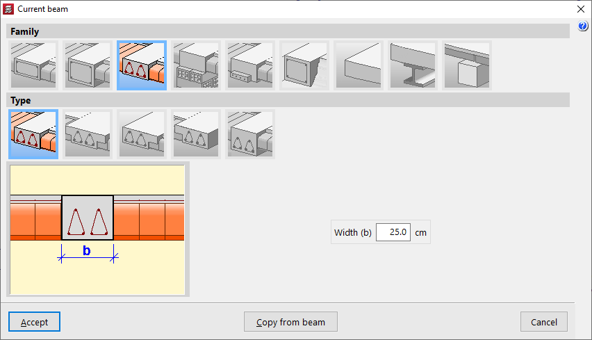
Lattice beams
"Lattice beams" are a type of beam with prefabricated reinforcement. Their characteristics must be supplied by the manufacturer and defined within the general project data ("Project"> "General data" > "By position" > "Beam options" > "Formwork arrangements" > "Lattice beams"). The following options are available:
- Rectangular flat lattice beam
- T-shaped lattice beam
- Lattice beam with wing on the right
- Lattice beam on the left
- Rectangular suspended lattice beam
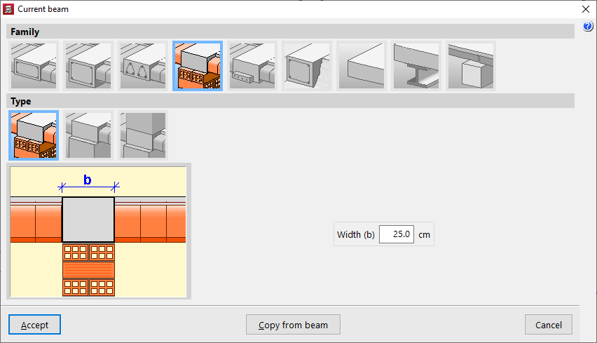
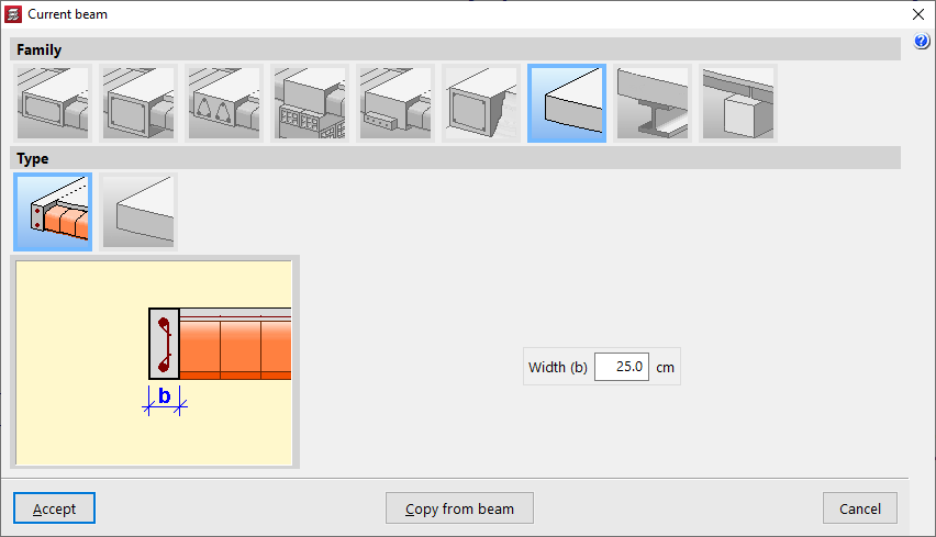
Beams with external connection
"External connection beams" allow you to simulate a linear support on which the rest of the modelled structure can rest. The following types of external connection beams are available:
- Wall support
This element only prevents movement on the vertical axis, allowing rotation and movement on the horizontal plane. It is used to simulate a movable or expansion support.
- Wall support
This element constrains all movements, both vertical and horizontal, but allows rotation. It is used to simulate a fixed articulated support.
- Embedding
This element constrains both displacement and rotation.
In all three cases, the program only requests the "Width (b)" of the support.
Prestressed beams
"Prestressed beams" have a prefabricated base and form their complete section during concreting together with the slab and the negative reinforcement placed in situ.
To define them, you need to edit the prestressed beam library by clicking on the corresponding button. Select "New", define the "Reference", the "Geometry", the characteristics of the "Materials", both for the concrete and the longitudinal reinforcement, and add the available "Section types".
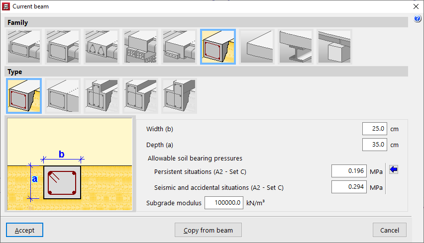
Foundation beams
"Foundation beams" are beams supported on the ground. To simulate the ground, elastic connections are automatically generated along the entire length of the foundation beam during the analysis process.
Among the available options are the following:
- Rectangular foundation beam
- Flat foundation beam
- Inverted T-shaped foundation beam
- Foundation beam with right-hand flange
- Foundation beam with left-hand flange
The value of the ballast modulus must be specified, as it will influence the stiffness of the elastic connections, as well as the "Allowable soil bearing pressures" in "Persistent situations" and "Seismic and accidental situations". You can "Import usual design values" for the permissible soil stresses using the button on the right.
In addition, the geometric properties of the beam are indicated, such as the "Width (b)", the "Depth (a)", if it is not a flat beam, and in the case of inverted T-beams or beams with flanges, the "Flap depth (s)" and the length of the "Left flap (i)" and the "Right flap (d)".
Non-structural or boundary hoop
A "non-structural or boundary hoop" is an element that contributes weight in the calculation (if it has width), but has no structural function. These elements are used to delimit the outline of floor slabs, especially two-way slabs or slabs.
Within this family, the following can be created:
- Non-structural or boundary hoop
This element allows you to represent a hoop with a certain "Width (b)".
- Non-structural hoop or zero width limit
This element has no width and is represented as a boundary line on the plan.
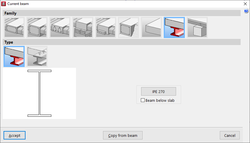
Steel beams
Within the "Steel beams" family, two types are available:
- Steel beam
This type corresponds to steel beams themselves. Only the metal section will be used in the calculation. If the "Beam under slab" box is checked, the weight of the concrete above the beam width will also be added. By clicking on the corresponding button on the right, you can access the "Section selection" panel, which allows you to choose from a variety of available sections, including beams with "Rolled steel section", "Reinforced rolled steel sheet section" and "Formed steel section".
- Composite beams
In this type, the concrete head works in conjunction with the metal profile. Therefore, in addition to selecting the "Section series" and the "Section", the "Connectors" must be defined, indicating their "Nominal diameter", the "Minimum length" and the connector head data ("Head thickness" and "Head diameter"), as well as its "Breaking stress".
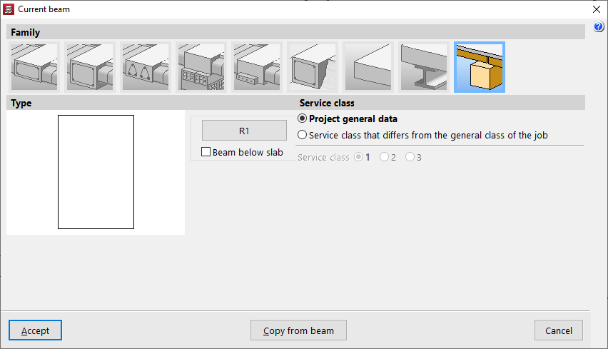
Timber beams
The "Timber beams" family allows the use of beams made from this material.
The geometry of the timber section is defined using the corresponding button, which opens the "Section selection" window.
The box "Beam under floor slab" allows you to indicate whether this is the case.
As for the "Service class", this may be the one defined in the "Project general data", but a "Service class that differs from the general class of the job" may also be applied.