Field of application
CYPEPLUMBING Sanitary Systems carries out the analysis and design of all foul water and rainwater evacuation installations or only those selected by users, for any type of building, in compliance with predefined standards, personalised design configurations of other standards, or personal technical configurations.
| Country | Standard |
 | CTE DB HS5 |
| RENISDA | |
 | NBR 8160:1999 NBR 10844:1989 |
| RIDDA | |
 | NTC 1500 |
 | NF DTU 60.11 |
 | UNI EN 12056 |
 | Código de edificación de vivienda Capítulo 42 - Drenaje sanitario |
| I.S. 010 | |
 | DR n.º 23/95 (RGSPPDADAR) |
| Code of practice on sewerage and sanitary works | |
 | BS EN 12056, System III |
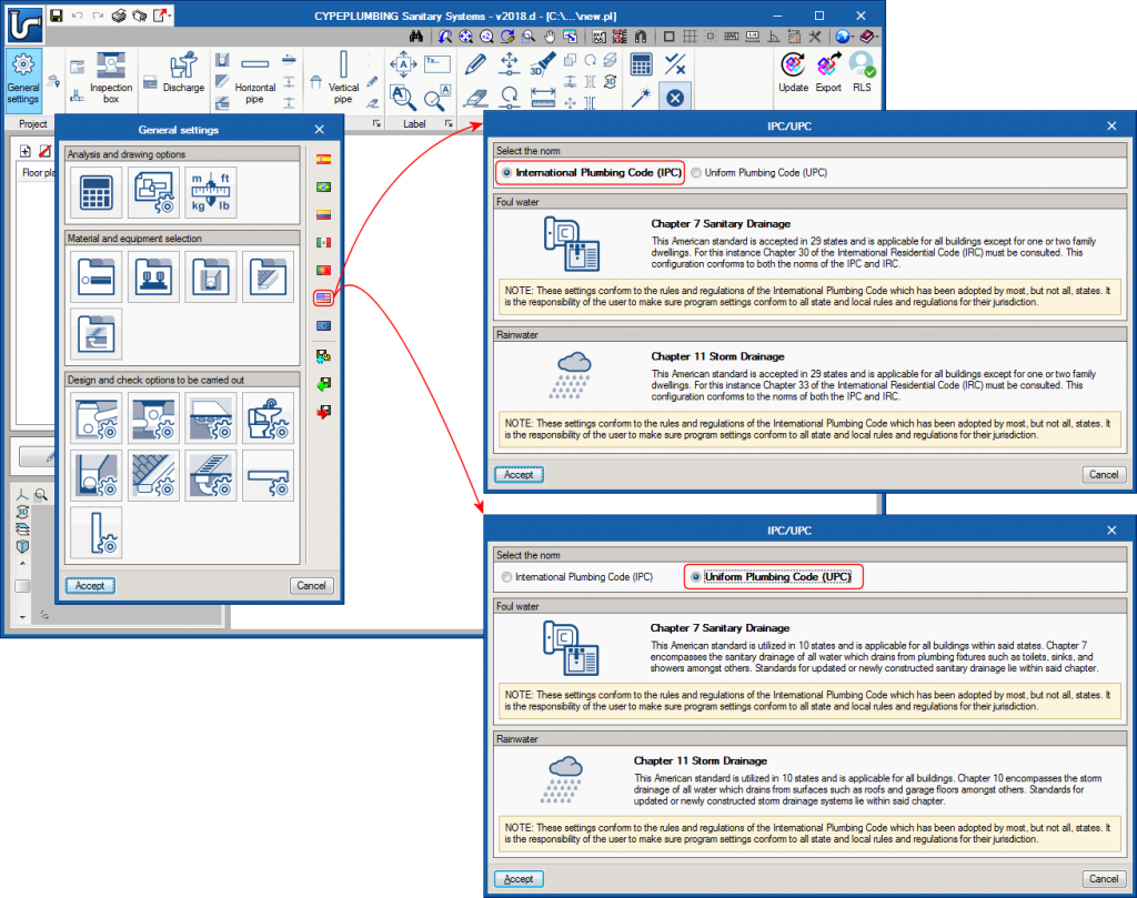
 | IPCUPC |
 | EN 12056 |
 | Normativas configurables |
Program settings
The program allows users to define all the settings (drawing and calculation options, selection of materials and equipment, design options and checks to be carried out) that are required to introduce and design the installation in accordance with the standards described above. Additionally, users can personalise the program settings.
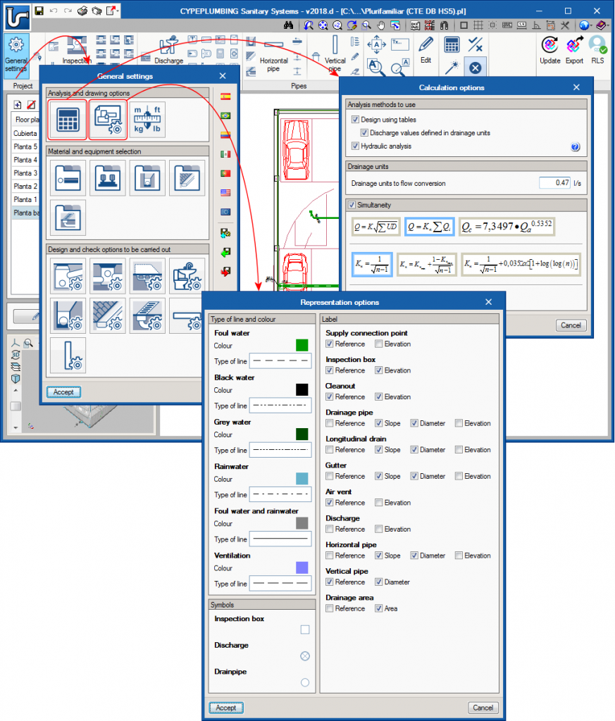
Drawing and calculation options
CYPEPLUMBING Sanitary Systems carries out the design in accordance with several calculation methodologies:
- Design using tables (use of tables by drainage units, areas or flows)
- Hydraulic analysis applying several formulae: Manning, Wyly-Eaton, Dawson and Hunter
Users can define a general configuration for drawings. It is possible to choose the type of line to use for installation layers, the colour of those layers, general symbols to be applied and references to be printed on floor plans.
Selection of materials and equipment
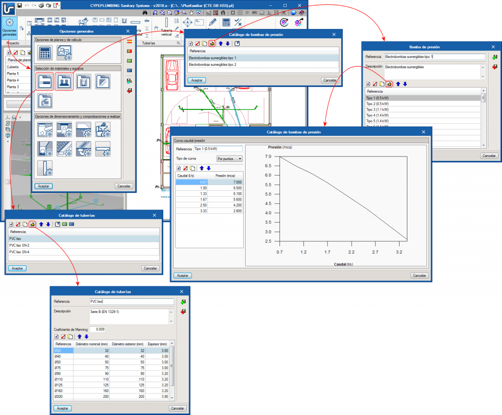
The program contains catalogues of predefined equipment to develop the installation and allows users to introduce catalogues, which they themselves can configure.
Design options and checks to be carried out
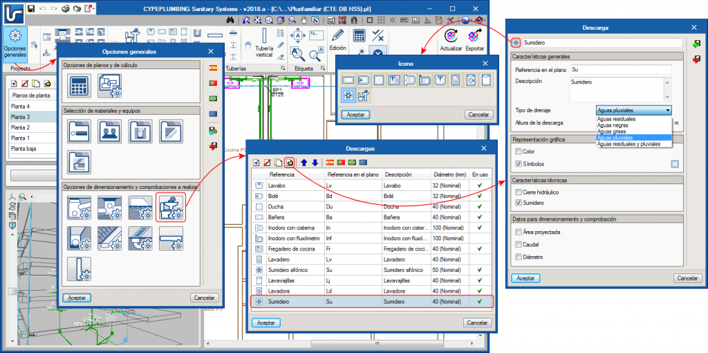
CYPEPLUMBING Sanitary Systems also allows for the design and checks to be carried out to be configured for any element of the installation, supply connections, inspection boxes, drainage areas, discharges, drainage pipes, gutters, longitudinal drains, and horizontal and vertical pipes.
Workspace
The program is designed to carry out the design of the installation in a 2D workspace with the possibility to view, in real time, the 3D view of the installation that has been introduced.
The program allows for the design to be carried out on 2D templates from the BIM model using IFC format or DXF-DWG templates, DWF or images (.jpeg, .jpg, .bmp, .wmf).
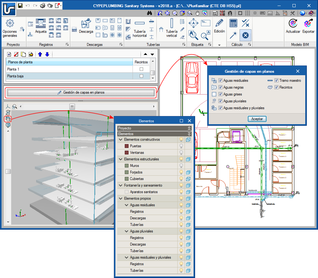
It is also possible to work by layers, on the different networks the program allows users to design:
- Foul water network
- Rainwater network
- Foul water and rainwater network (mixed system)
- Grey water network
- Black water network
These layers can be managed in the 2D and 3D workspaces.
Calculations and checks
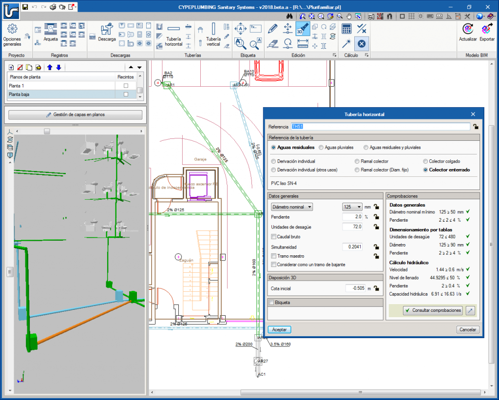
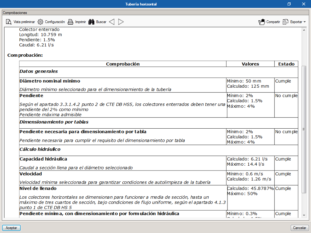
The program designs networks in accordance with the selected standard or personalised configuration to apply, and carries out the required checks.
The analysis of the tree of the installation is carried out by calculating gross and simultaneous quantities of flow, where the simultaneity can be configured to be applied globally or locally.
It calculates and carries out a graphical representation of the main pipe span of the installation.
CYPEPLUMBING Sanitary Systems can design each element, i.e. a partial design of the complete installation, or an automatic global design of the complete installation, optimising the space required by the pipe in the free height of the floor and the excavation volumes.
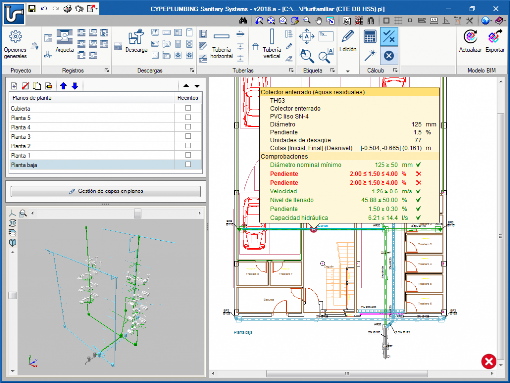
Using warnings, the program informs users of any non-conformity with the code or any installations that have been developed incorrectly, to aid them with the correct configuration.
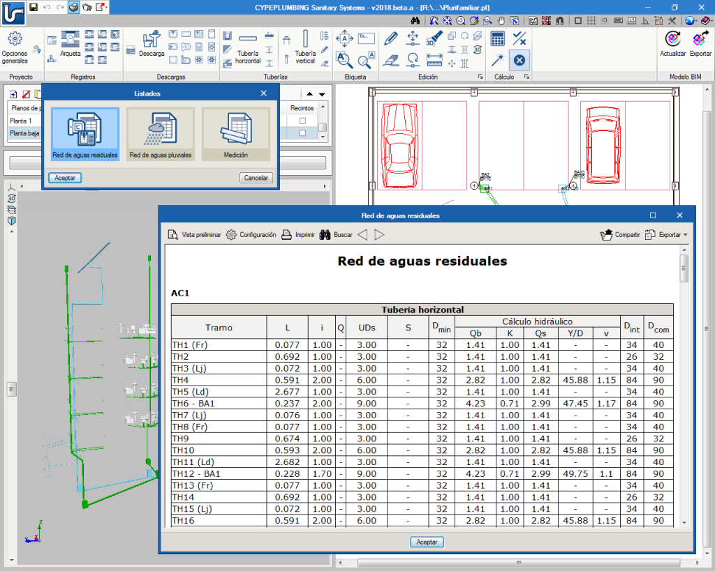
The results can be viewed on the elements and also in the results reports that are generated by the program.
Graphical analysis of the results
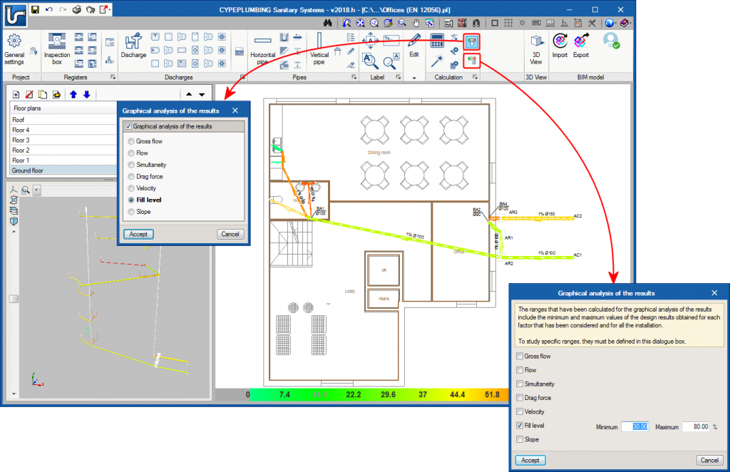
CYPEPLUMBING Sanitary Systems allows users to graphically analyse the results of the installation. Users can select the parameters that intervene in the hydraulic design of the installation that they wish to analyse, and the program draws the installation using a colour scale, for a quick and easy view of the results in the 2D and 3D views it provides on-screen. It is possible to study specific result ranges in the global aspect of the installation.
Documents
The program generates the following documents:
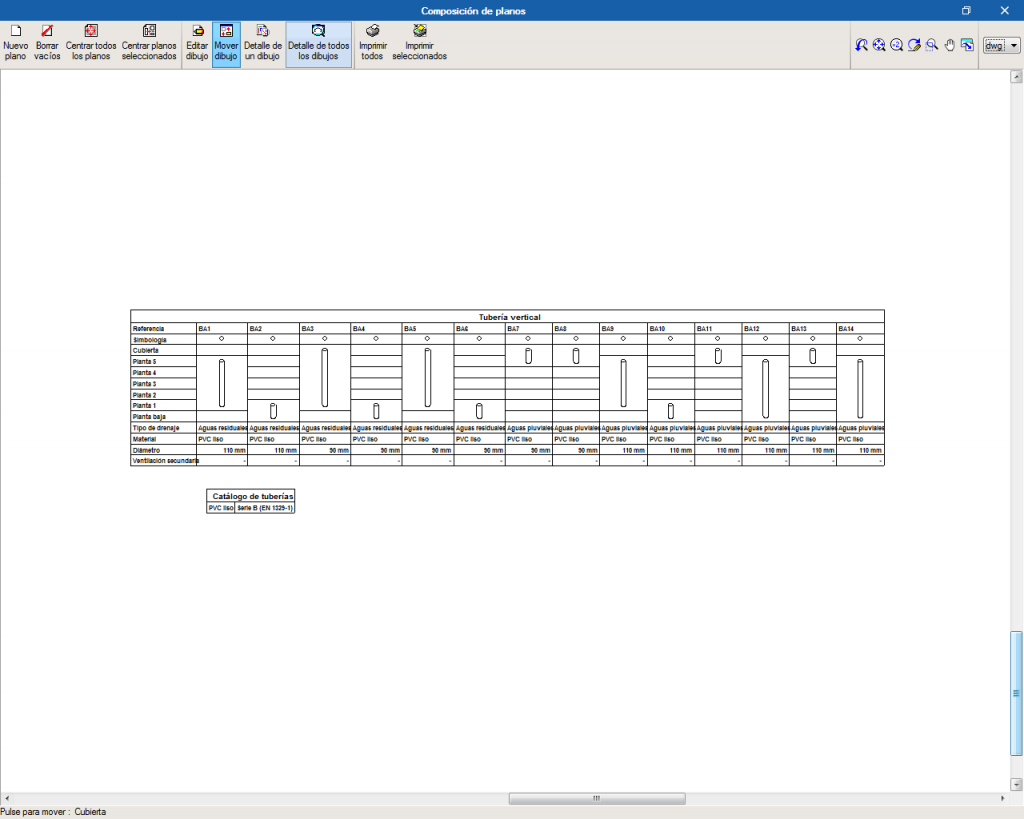
- Drains diagram
- Results, checks and quantities reports
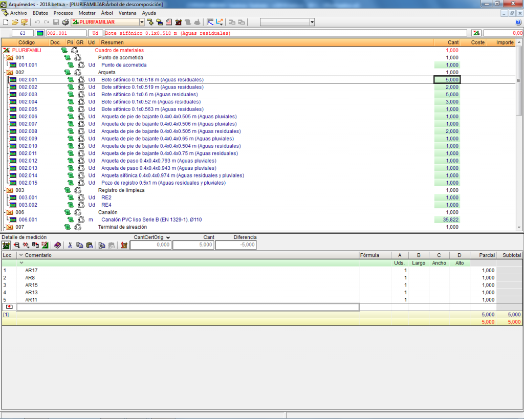
- Export of the quantities to BC3 format
Drawings and diagrams
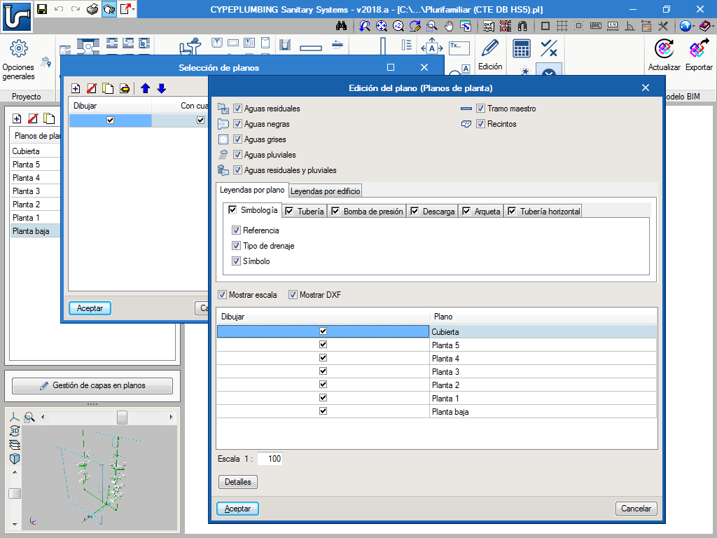
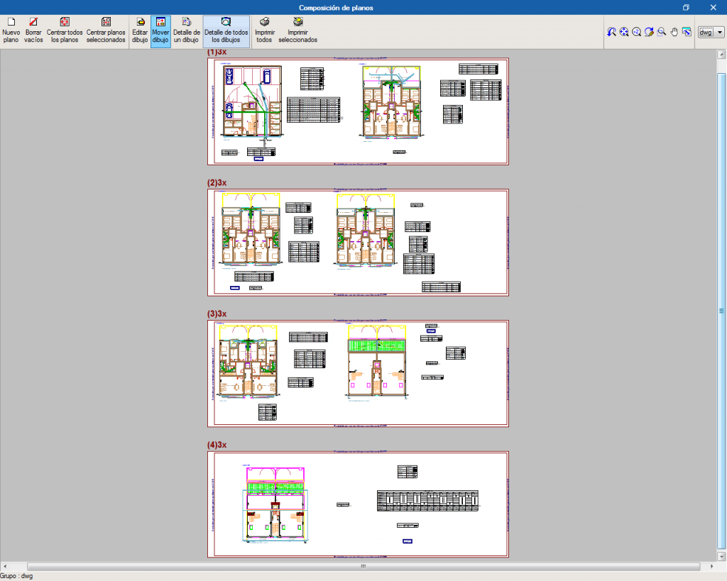
CYPEPLUMBING Sanitary Systems generates floor plans with several configuration possibilities:
- Floor plans of the building (groups all the keys of the floor plans) or per plane.
- Floor plans with the possibility to manage the wastewater networks on different drawings.
It is possible to print and/or export the diagrams and drawing from the program to different formats (DXF, DWG, JPG, EMF, BMP).
Results reports
The program generates reports containing the results obtained for the installations. The reports generated from the design of the installations can be printed out directly from the program or exported to several formats (TXT, HTML, RTF, DOCX, PDF).
The program generates the quantities report of the installation including the quantities of the pipes and equipment. These quantities can be exported to FIEBDC-3 (BC3) format.
User license
To be able to work with CYPEPLUMBING Sanitary Systems, users must have the corresponding permission to use the program.

