
Workflows supported by the program
As CYPETHERM EPlus is an Open BIM tool and is connected to the BIMserver.center platform, it offers different workflow options.
To carry out the energy simulation, the geometric model can be created from scratch in CYPETHERM EPlus or generated beforehand using various alternative software packages, such as IFC Builder, CYPE Architecture or other modelling software.
Data entry
If you link the CYPETHERM EPlus job to a BIM project on the BIMserver.center platform, you can perform the following actions.
If the model is not imported from the information contained in a BIM project on the BIMserver.center platform, you can carry out the following actions:
Importing BIM models from BIMserver.center
If the CYPETHERM EPlus job is linked to a BIM project on the BIMserver.center platform, the following actions can be carried out:
- Importing the model with the geometry of a building. This generates the geometrical information of the model such as zones, spaces, opaque elements, openings and own shadows. Among the available options are the following:
- If the model has been designed in CYPE Architecture and shared in BIMserver.center, after going through Open BIM Analytical Model, the analytical model generated by this program can be imported and shared again in BIMserver.center.
- If the model has been designed in IFC Builder and shared in BIMserver.center, the geometric information can be imported without using any intermediate program.
- If the model has been designed in Autodesk Revit, its information must be shared in BIMserver.center using the Open BIM - Revit Plugin. After passing through Open BIM Analytical Model, the analytical model generated by this program can be imported and shared again in BIMserver.center.
- If the model has been designed in CAD/BIM programs such as Allplan, ArchiCAD and others capable of generating a file in IFC format, this file must be incorporated into the BIMserver.center project using IFC Uploader. After going through Open BIM Analytical Model, the analytical model generated by this program can be imported and shared again in BIMserver.center.
- Importing the model with the building's construction systems. This generates the information relating to the building elements in the building model. Among the available options are the following:
- Importing construction systems designed in CYPE Construction Systems. The CYPE Construction Systems step is useful if CYPE Architecture, Revit or other CAD/BIM programs have been used to create the geometric model, or if IFC Builder has been used without entering the information relating to the construction systems.
- Importing construction systems designed in IFC Builder.
- Importing models with the geometry of nearby buildings or other obstacles. This allows remote shadows to be generated. Among the available options are the following:
- Importing shadows based on the buildings entered in the model designed in Open BIM Site and shared in BIMserver.center. After going through Open BIM Analytical Model, the analytical model generated by this program can be imported and shared again in BIMserver.center.
- Importing shadows based on nearby buildings and other obstacles from the model designed in IFC Builder.
- Importing the model with the lighting analysis of the building. This makes it possible to incorporate the data on the installed lighting power in the spaces. The available options include the following:
- Importing the installed lighting power in the model spaces developed in CYPELUX.
- In some versions, it is possible to import the model with the building's air conditioning system defined with manufacturer equipment. This makes it possible to generate the HVAC systems and the associated terminal units by selecting the corresponding devices and systems. The available options include the following:
- Importing the building's air-conditioning system from models created in Open BIM DAIKIN.
- Importing the building's air-conditioning system from models created in Open BIM FUJITSU.
- Importing the building's HVAC system from models created in Open BIM VAILLANT.
Free editing
- If adjustments are required, the data for the building elements can be entered or edited numerically in CYPETHERM EPlus in the tree available in the "Building" tab.
If the model is not imported from the information contained in a BIM project on the BIMserver.center platform, you can perform the following actions:
Freeform modelling / Modelling with templates
- The geometric and structural model of the building, as well as neighbouring buildings and other obstacles, can be drawn directly from scratch in CYPETHERM EPlus by freehand drawing in the "3D Model" tab.
- Modelling in the "3D Model" tab of CYPETHERM EPlus can be carried out using templates in DXF-DWG, DWF or image formats (.jpeg, .jpg, .bmp, .wmf).
Importing IFC files and generating the 3D model
- If you have an IFC file containing the building’s geometry, you can import it into the "3D Model" tab of CYPETHERM EPlus using the "Import IFC" option and, with the help of a wizard, automatically generate the geometry for the following model elements: walls, floors, roofs, windows, doors and skylights. You can then make the necessary adjustments in the "3D Model" tab to complete it.
Once the building geometry has been created or imported and adjusted in the "3D Model" tab, the program allows you to generate the thermal model using the relevant option, thereby moving on to the "Energy simulation" tab.
Data output
CYPETHERM EPlus provides the following data output options:
- Exporting reports to HTML, DOCX, PDF, RTF and TXT formats.
- Exporting drawings to DXF, DWG and PDF formats.
- Exporting data generated in CYPETHERM EPlus to the BIMserver.center platform using the IFC format. The energy simulation data generated in CYPETHERM EPlus can be used for a new project, as well as in CYPETHERM EPlus, to carry out energy and economic analyses of various building improvement measures.
Sequence of input and output of data for the energy simulation of a building
The energy simulation of a building can be carried out in the program using the following input and output sequence:
- Creating a new job (from "File", "New") and select the "Energy simulation" option.
- (Optional) Linking to BIMserver.center. The building geometry, construction systems, shadows, lighting power of spaces and the definition of some air conditioning systems can be imported from the BIM model. During the import process, the ventilation of the living areas is also configured, and edge processing can be carried out where necessary.
- (Optional) If the model has not been imported from the data stored on BIMserver.center, it must be entered in the "3D Model" tab and the "Geometric model" option must then be used to transfer the data to the "Building" tab.
- In the "Building" tab, the definition of the building model is completed:
- Review and/or definition of the general project data (from the "General data" section), including general parameters and site data.
- Review and/or definition of the room characteristics via the library management system (side menu: "Building", "Library", "Rooms").
- (Optional) If the construction solutions have not been imported, defining the characteristics of the construction elements via the management of their libraries (sidebar "Building", "Library", "Construction elements/Glazed openings/Doors").
- (Optional) If not done previously, edge processing is carried out (using the "Edge processing" option in the top bar) for generating and processing linear thermal bridges.
- (Optional) Review, adjustment and validation of the data presented by the building model and its structure in zones, spaces and elements, self-shadows and cast shadows (sidebar "Building", "Zones/Self-shadows/Cast shadows").
- Review, input and/or editing of DHW systems and HVAC systems (using the tools in the ‘Building’ side panel, under "Zones", "Terminal units/DHW systems/HVAC systems", or via the options in the "Systems" group on the top bar).
- Model validation of the building (from "Errors", "Validate model") and correction of errors and warnings by editing the data in this tab.
- On the "Analysis" tab, you can configure the calculation options, perform the analysis and view the results.
- Adjusting the analysis options (the "Analysis" section, "Analysis options").
- Analysis and energy simulation of the building (the "Analysis" section, "Analysis").
- (Optional) Viewing the analysis results on screen in the main display area, at the building or zone level (depending on your selection in the "Building" side tree).
- Generating reports (using the options in the “Reports” section) and analysis files (using the options in the "Analysis" section).
- (Optional) Viewing data on floor plans (the "Floor plans" tab).
- (Optional) Obtaining floor plans (via the "Floor plans" option in the "File" menu or at the top of the interface).
- Exporting to BIMserver.center (the "BIMserver.center" section, "Share").
Examples of models for building energy simulation
Below is an example of a building model that can be created in the program, showing the layout of the elements and the options available for adding them to the model, and which can be used to carry out an energy simulation.
A development comprising 8 terraced houses
Architectural geometry can be entered into the program or imported from a BIM model. The following elements must be checked and defined:
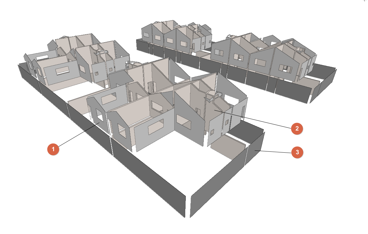
- External walls
- Generated when importing the BIM model or added from "3D Model". Defined under the "Building" tab, in the "Library" tree, under "Building elements > Façade".
- Partition walls
- Generated when importing the BIM model or added from "3D Model". Defined via the "Building" tab, "Library" tree, "Building elements" > "Partition wall".
- Walls in contact with the ground
- Generated when importing the BIM model or added from "3D Model". Defined via the "Building" tab, "Library" tree, "Building elements" > "Basement wall".
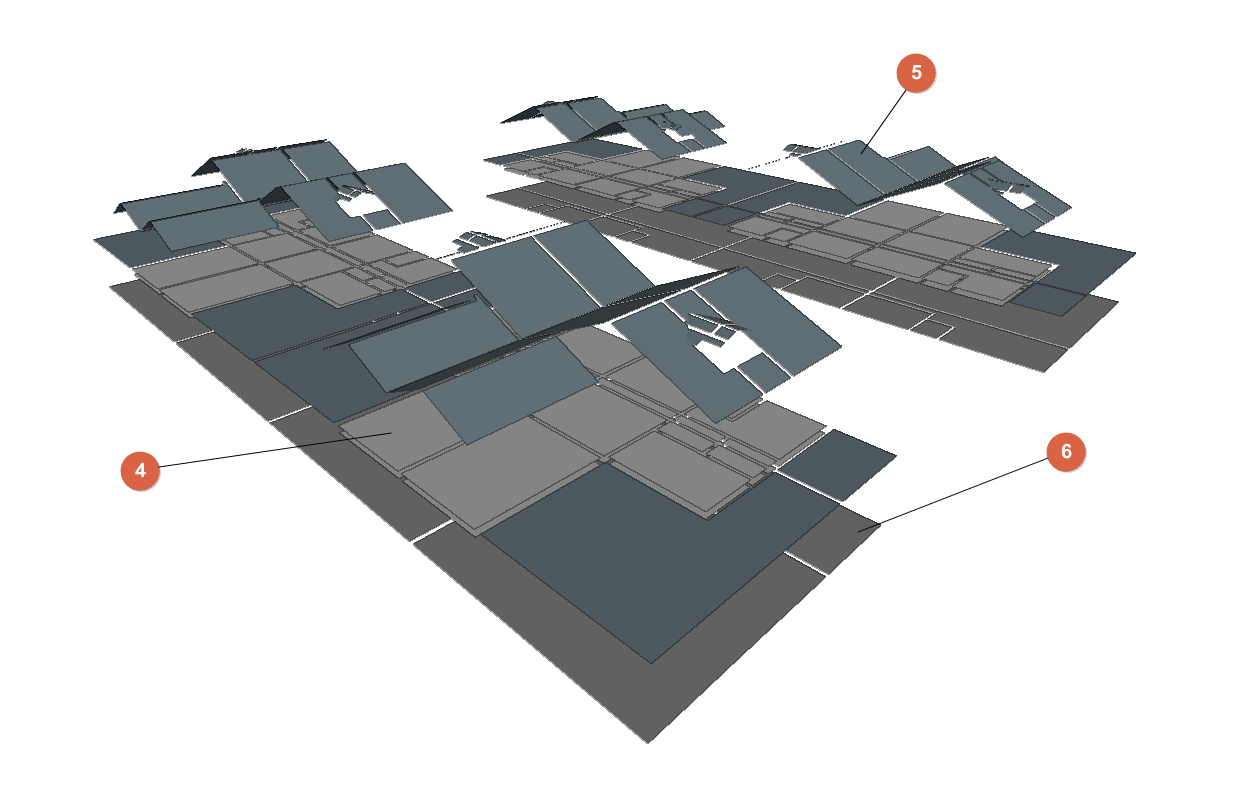
- Floor slabs between floors
- Generated when importing the BIM model or added from "3D Model". Defined via the "Building" tab, "Library" tree, "Building elements" > "Floor slab".
- Roof
- Generated when importing the BIM model or added via "3D Model". Defined via the "Building" tab, "Library" tree, "Building elements" > "Roof".
- Slabs-on-ground
- Generated when importing the BIM model or added via "3D Model". Defined via the "Building" tab, "Library" tree, "Building elements" > "Floor slab".
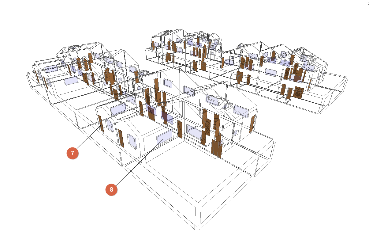
- Doors
- Generated when importing the BIM model or added from "3D Model". Defined in the "Building" tab, under the "Library" tree, in "Doors".
- Windows
- Generated when importing the BIM model or added from "3D Model". Defined in the "Building" tab, under the "Library" tree, in "Glazed openings".
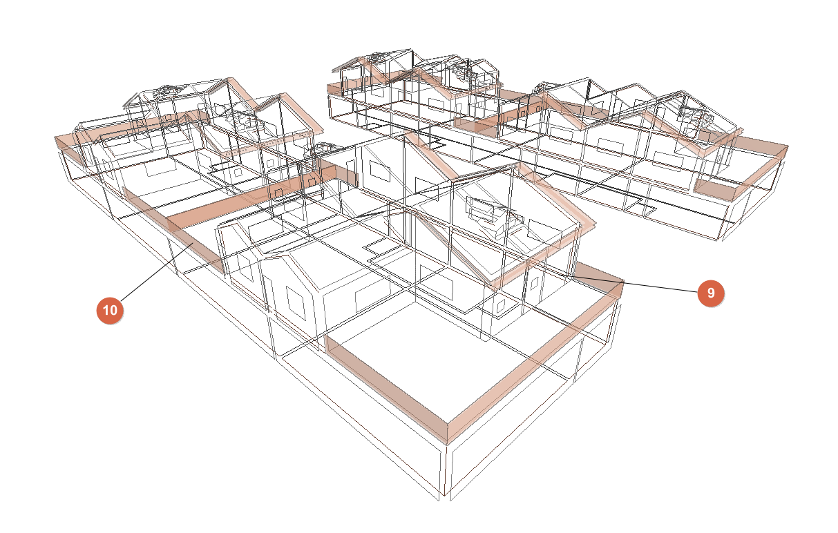
- Linear thermal bridges and edges
- Edges generated when importing the BIM model or when generating the thermal model from "3D Model". Linear thermal bridges generated from the "Building" tab, under the "Edge processing" option.
- Shadows
- Generated when importing the BIM model or when generating the thermal model from "3D model".
- Venues (not shown in the diagram):
- Generated when importing the BIM model or added from "3D Model". Defined in the "Building" tab, under the "Library" tree, in "Spaces".
- Air conditioning and DHW systems (not shown in the diagram)
- Generated from "Air conditioning system" / "Terminal units" and "DHW systems".
Creating a new job, linking to a project and importing data
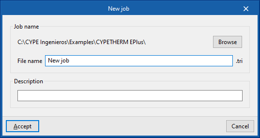
When you launch the application and click on "New", you are given the option to create a "New job". In the pop-up window, you can enter the "File name" and its "Description".
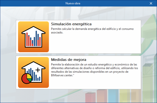
Next, you must specify whether the purpose of the project is to carry out an "Energy simulation" or to conduct a study of "Improvement measures" or alternative building designs.
You should select the first option to access the specific interface for carrying out the building’s energy simulation, which includes the option to calculate energy demand and associated consumption.
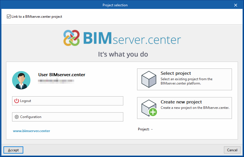
The project can subsequently be linked to a BIMserver.center project.
This is done in the "Project selection" window, which offers the following options:
- On the left-hand side, you can log in using a BIMserver.center account.
- On the right-hand side, you will find the "Select project" option to choose an existing project. You also have the option to "Create a new project". In that case, the project you create will be visible on BIMserver.center from that point onwards.
Once the new project has been created, you will be taken to the program’s main interface. At any stage of the project, you can share or import project files via the “BIMserver.center” panel, located in the top-right-hand corner of the main interface.
Importing BIM models
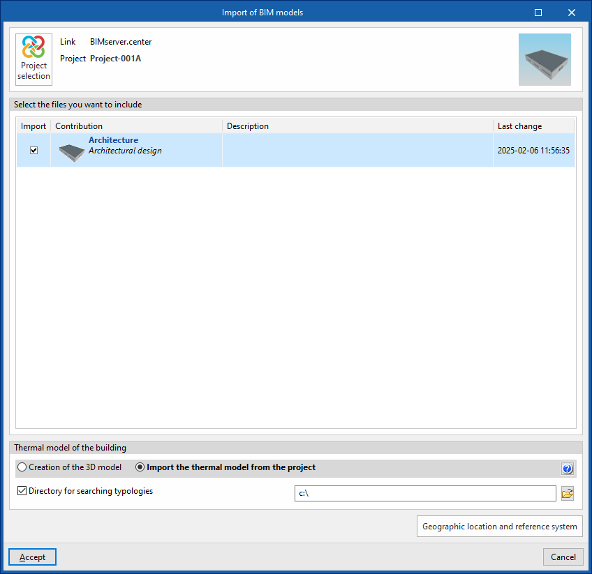
When creating a new project, after selecting or creating a project hosted on the BIMserver.center platform, the "Import BIM Models" window appears, displaying the files contained in that project in IFC format.
The app allows you to include one or more of the existing models in that project. To do this, tick the "Import" box and confirm.
At the bottom of the import window, you will see the "Building thermal model" section, which contains the following options:
- Creating the 3D model
If this option is selected, the program will open the "3D Model" tab, where you can design the building's geometry. - Importing the project's thermal model
If this option is selected, the program will import the building geometry from the information contained in the models included in the BIMserver.center project and will not enable the "3D Model" tab.
In the latter case, the program offers the following option:
- Directory for searching for types (optional)
When this option is enabled, you can select a directory on the hard drive where the type library files are stored. This allows you to import type libraries previously created in other projects and exported to that directory, and automatically assign them to the spaces, elements and openings in the imported model. To do this, the references of the types in the selected directory must match the references of the element types in the imported model.
| Note: |
|---|
| If you have started the workflow in CYPE Architecture or in software such as Revit and other modelling tools, sharing the model via the Open BIM - Revit plugin or the IFC Uploader, the model to be imported must be the one provided by Open BIM Analytical Model. |
Final import settings
The program will then open the "General parameters", "Site data" and, where applicable, the "Ventilation (Living areas)" and "Edge processing" windows, so that the relevant parameters can be configured.
The program will open on the "Building" tab and will have generated the model geometry and element libraries based on the data available in the project or in the selected directory. At this point, you can enter the necessary data to continue working on the model.
| Note: |
|---|
| In the building’s tree view, library categories that have not yet been defined will be marked with an orange icon. If "Edge processing" has not been carried out during import, and provided that the BIM model’s edges have been imported, the thermal bridge category in the library will appear as undefined. To perform automatic thermal bridge management, the rest of the model must be defined and free of errors. At that point, you can use the "Edge processing" button to automatically define linear thermal bridges. |