Air conditioning systems. General
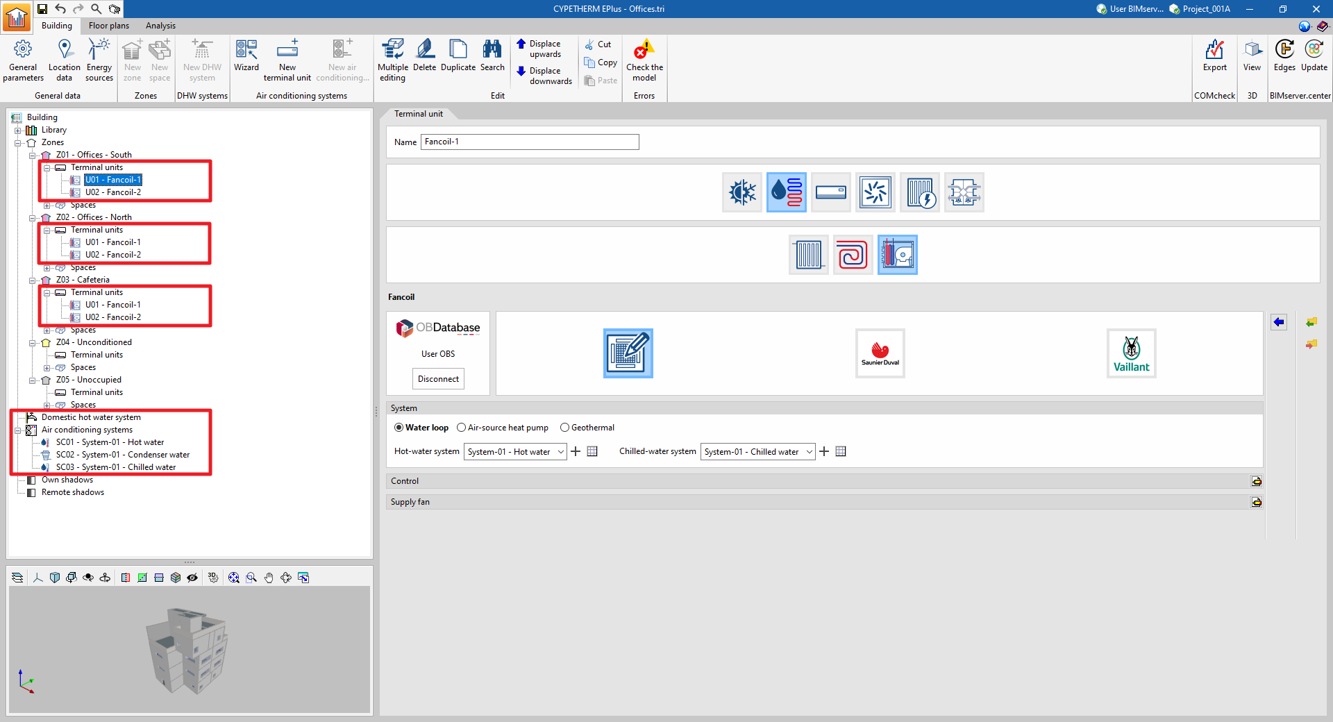
In the CYPETHERM energy simulation programs that use the EnergyPlus™ calculation engine, the building's climate control systems are defined in two sections of the diagram in the "Building" tab:
- (1) Terminal units (within each "Zone" section).
These are the units that are located in the spaces and come into contact with the air in these spaces.
- (2) Air conditioning systems (in the specific section).
These are centralised production units and centralised air-conditioning units serving terminal units or other air conditioning systems. Together with the centralised units, the relevant features of the working fluid distribution network are also defined.
Generally, a complete air conditioning system consists of one or more terminal units connected to a centralised system, which in turn may require other production systems. For example, in an all-air system, the supply air terminals are the terminal units and the air handling unit (AHU) is the centralised system. If the AHU contains a chilled water coil, users will need to define an additional production system that generates the chilled water.
There may also be air conditioning systems composed only of terminal units: this is the case of electric radiators or 1x1 split-type units.
In the programs, air conditioning systems and their terminal units are classified according to the type of fluid that combats the space load. Thus, a distinction is made between air conditioning systems and water, direct expansion (refrigerant) and air terminal units. Furthermore, the program includes the definition of other stand-alone terminal units and water condensing systems for chillers and reversible heat pumps.
This includes the possibility of defining any type of air conditioning system, as well as identifying its average seasonal performance in terms of cooling and/or heating production and the type of energy it consumes, through the terminal unit of the "Constant performance equipment" type.
An assistant is provided to define the building's air conditioning systems. Depending on the type of system chosen, the assistant will successively display the definition panels corresponding to the different units in the air conditioning system.
Air conditioning systems. Manual definition
Manually defined centralised production systems
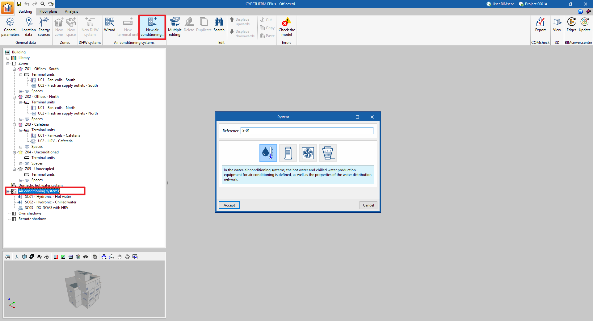
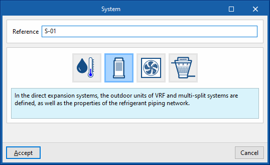
To manually add a new centralised production system, select the "Air conditioning systems" section in the building diagram and click on the "New air conditioning system" button in the top toolbar.
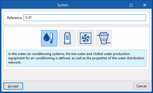
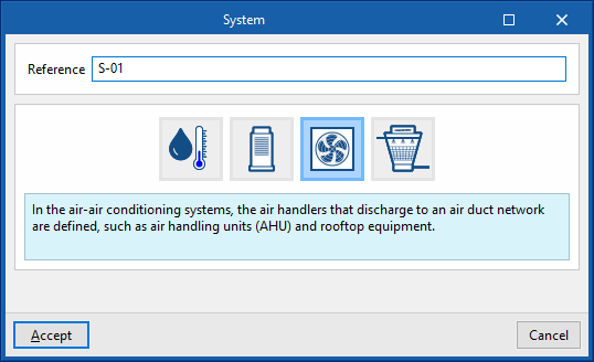
This will display a pop-up window in which the type of production system can be selected from "Water-air conditioning system", "Direct expansion system" (refrigerant), "Air-air conditioning system" or "Water-cooled system".
By choosing one of these general typologies, a new window opens where the specific type of system is selected and its characteristics are defined.
The following types and sub-types of centralised production systems are available:
- Water-air conditioning system
- Chilled-water system
- Hot-water system
- Domestic heat pump system
- Geometric heat pump

- Direct expansion systems
- Variable refrigerant flow systems (VRF)
- Multisplit

- Air-air conditioning system
- Central ventilation system
- Heat recovery unit
- Dedicated outdoor air system (DOAS)
- Air handling unit, constant air flow system
- Air handling unit, variable airflow system
- Air handling unit, constant flow all-air system with double duct
- Air handling unit, variable flow all-air system with double duct
- Central ventilation system

- Water-cooled system
- Water-cooled system for reversible heat pumps
- Water-cooled system for chillers
- Water condensation system at a defined temperature

By selecting the type of unit, the editing panel is updated to show its characteristics. In some categories, under the logos of different manufacturers, users are offered the possibility of selecting units from their commercial catalogues. The characteristics of these units are completely defined within the program, so users simply have to indicate the characteristics relating to their installation.
The following general features are offered in the air conditioning editing panels:
 Restores the default values proposed by the program.
- Displays and edits advanced features of the air conditioning system.
 Imports air conditioning system information from a file on disk.
 Exports the climate control system information to a file saved on disk.
If a value is not specified for certain characteristics of the units, such as the nominal capacity of a production unit or the flow rate of a fan, the autosize function of EnergyPlus™ is used. This function will calculate non-user-defined values based on the requirements of the connected terminal units and the unit design characteristics.
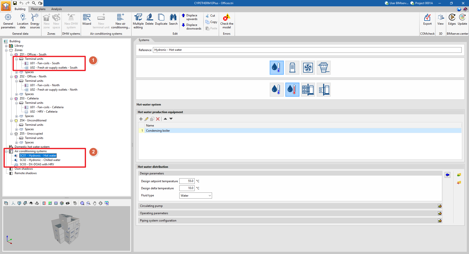
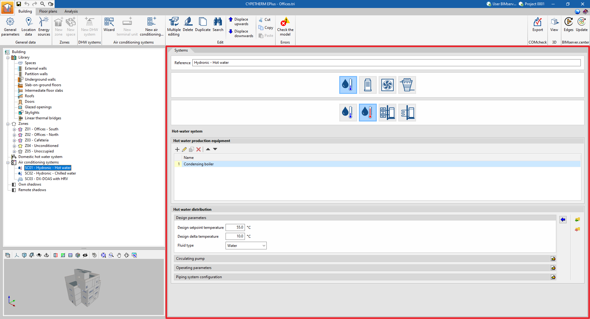
When a new centralised production system has been created, it will appear as an element in the "Air conditioning systems" section of the diagram. When it is selected, the editing panel is displayed on the centre right-hand side of the general interface.
Using the options in the "Edit" group of the upper toolbar or by right-clicking on the element in the diagram, it can also be duplicated, deleted, moved in the list, cut or copied.
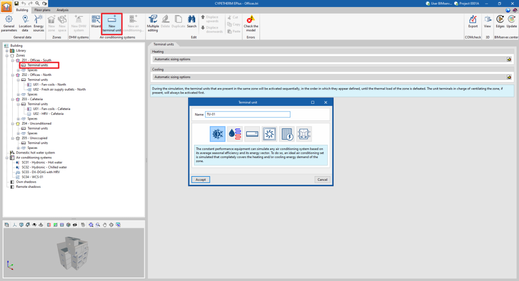
Manually defining terminal units
Terminal units for air-conditioning systems are defined manually in a similar way to those for centralised production systems. To add a new terminal unit, select the "Terminal units" section of the building diagram, within the "Zone" where it is to be added, and click on the "New terminal unit" option in the top toolbar.
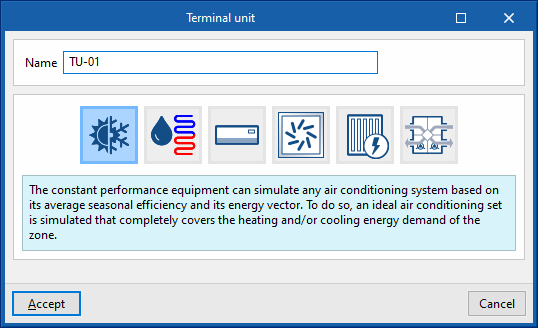
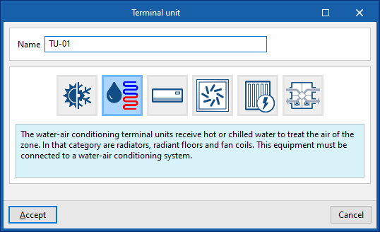
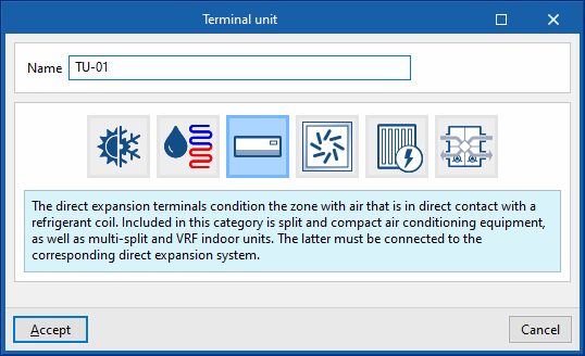
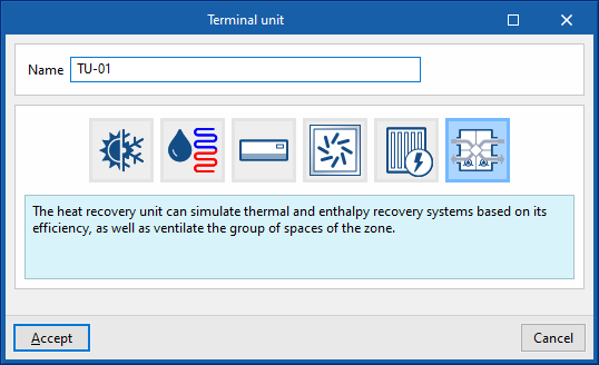
A pop-up window appears where the type of terminal unit is selected from among "Constant performance equipment", "Water terminal unit", "Direct expansion terminal unit", "Air terminal unit", "Electric heater" and "Heat recovery unit".
By choosing one of these general types, a new window opens in which the specific type of terminal unit is selected and its characteristics are defined.
The types and sub-types of terminal units available are as follows:
- Constant performance equipment
- Heating
- Cooling
- Both

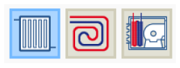
- Water terminal unit
- Radiator
- Radiant floor
- Fan coil
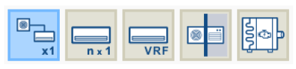
- Direct expansion terminal unit
- Split 1x1
- Multisplit
- VRF
- Packaged terminal unit
- Water to air heat pump
- Air terminal unit
- Air supply outlet
- Air supply outlet, double duct
- Variable air volume box
- Variable air volume box, double duct

- Electric heater

- Heat recovery unit

Just as with the centralised part of the air-conditioning systems, selecting the type of terminal unit updates the editing panel to show its characteristics. Within some categories, under the logos of different manufacturers, users can select units from their commercial catalogues. The characteristics of these units are completely defined within the program so that the user only has to indicate the characteristics relating to their installation.
The following general features are provided in the terminal unit editing panels:
- Restores the default values proposed by the program.
- Displays and edits advanced features of the terminal unit.
- Imports terminal unit information from a file on disk.
- Exports terminal unit information from a file on disk.
If a value is not specified for certain characteristics of the equipment, such as its rated power or the flow rate of a fan, the EnergyPlus™ autosize function is used. This function calculates the non-user-defined values based on the thermal loads and autosize options for the zone.
The "System" section appears on the panels of the non-autonomous terminal units. The centralised system to which the unit is connected must be selected. The drop-down menu will only offer the systems compatible with the terminal unit defined in the job.
The list management buttons to the right of the drop-down menu are as follows:
 This defines a new centralised production system, of any type.
 Edits and selects a centralised production system defined in the job.
 Indicates that the selection made in the drop-down is empty or incorrect.
When the creation of a new terminal unit is completed, it will appear as an element within the "Terminal units" section of the diagram within each zone. When selected, its editing panel is displayed in the central right part of the general interface.
Using the options in the "Edit" group of the top toolbar or by right-clicking on the element in the diagram, it can also be duplicated, deleted, moved in the list, cut or copied.
Defining fans and circulator pumps
Within centralised air-conditioning systems, the relevant characteristics of the working fluid distribution network are also defined, which includes the fluid transport equipment, i.e. fans and circulator pumps.
Air-supply terminal units, such as fan coils, direct expansion (refrigerant) indoor units and heat recovery units, also contain fans.
The electricity consumption of these auxiliary units is included in the consumption of the heating and cooling services, except for the consumption of fans for centralised ventilation systems, which are charged to the ventilation service.
Fans
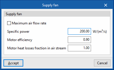
The fans are defined in a similar way for all devices in the program:
- Maximum air flow rate / Air flow (optional)
The air flow passing through the fan. If "Maximum air flow rate" is indicated in the panel, the air flow rate may vary during the simulation up to the value set in this box. If the air flow rate is not specified, the program will calculate the required air flow rate. - Specific power
The fan power consumption per m³/s of air flow it moves. If the performance value of the air conditioning unit includes the fan consumption, the value of the specific power can be set as 0 to avoid accounting for this consumption twice. - Motor efficiency
This is considered in the calculation of the heat losses of the electric motor of the fan, which will affect the supply air temperature according to the definition made in the following variable. - Motor heat losses fraction in air stream
If the supply air flows through the fan motor, the heat losses of the fan motor will cause an increase in air temperature. To consider this, a value of 1 should be set. If, on the other hand, the fan motor is outside the air flow, its heat losses will not affect it, so a value of 0 should be set.
Circulator pumps
Circulator pumps are also defined in a similar way in the different types of hydraulic circuits:
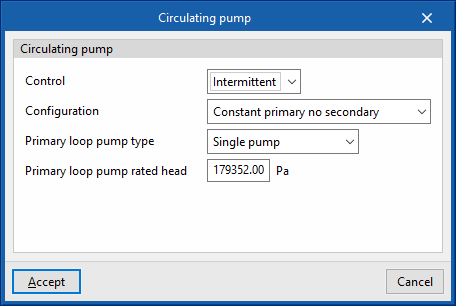
- Control
- Intermittent
If the control is intermittent, the pump is switched on and off at the same time as the air conditioning system. - Continuous
If the control is continuous, the pump is always on, even if there is no demand. In long periods of no demand, heat losses from the pump accumulate in the fluid, which can cause a significant rise in its temperature.
- Intermittent
- Configuration
The "Constant flow" and "Variable flow" represent a fixed or variable speed pump, respectively. - Type
Allows users to choose the number of identical pumps contained in the hydraulic circuit and their position. - Rated head
The pump head is involved in the analysis of the power consumption.
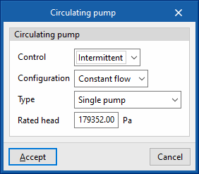
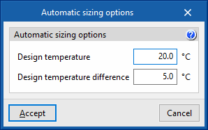
The water flow rate in the circuit is automatically determined by the calculation engine based on the heating or cooling demand on the day of design and the "Design temperature difference" specified in the hydraulic circuit.
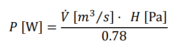
The electrical power of the circulation pump (P) is obtained from the water flow rate (V̇) and the head (H). The motor considers a fixed pump efficiency value equal to 0.78.
Examples
The combinations of air-conditioning systems and terminal units to be entered into the program for modelling different types of installation are shown below:
| Type of installation | Air conditioning system | Terminal unit |
| Constant performance equipment | None | - Constant performance equipment |
| Electric emitter installation | None | - Electric emitter for heating |
| Boiler, chiller and fan coils (air-cooled condenser) installation | - Water-air conditioning systems. Hot-water system - Water-air conditioning systems. Chilled-water system | - Water terminal unit. Fan coil |
| Boiler and radiator installation | - Water-air conditioning systems. Hot-water system | - Water terminal unit. Radiator |
| Boiler and radiant floor installation | - Water-air conditioning systems. Hot-water system | - Water terminal unit. Radiant floor |
| Aerothermal installation with fan coils | - Water-air conditioning systems. Domestic heat pump system | - Water terminal unit. Fan coils |
| Geothermal installation with fan coils | - Water-air conditioning systems. Geometric heat pump - Water condensation system at a defined temperature | - Water terminal unit. Fan coils |
| VRF/VRV installation (air-cooled condenser) | - Variable refrigerant flow systems (VRF) | - Direct expansion terminal unit. Variable refrigerant flow systems (VRF) |
| 1x1 split installation | None | - Direct expansion terminal unit. Split 1x1 |
| Multisplit installation | - Direct expansion systems. Multisplit | - Direct expansion terminal unit. Multisplit |
| Packaged terminal unit installation (electrical / gas) | None | - Direct expansion terminal unit. Packaged terminal unit |
| Compact equipment installation (hot water) | - Water-air conditioning systems. Hot-water system | - Direct expansion terminal unit. Packaged terminal unit |
| Heat recovery unit installation per zone | None | - Heat recovery unit |
| Centralised ventilation installation with heat recovery unit | - Central ventilation system. Heat recovery unit | - Air terminal unit. Air supply outlet |
| Centralised ventilation system with dedicated outdoor air system (DOAS) | - Central ventilation system. Dedicated outdoor air system (DOAS) | - Air terminal unit. Air supply outlet |
| Constant flow air conditioning installation | - Air handling unit, constant air flow system | - Air terminal unit. Air supply outlet |
| Variable flow air conditioning installation | - Air handling unit, variable flow all-air system | - Air terminal unit. Variable air volume box |
| Constant flow air conditioning installation, double duct | - Air handling unit, constant flow all-air system with double duct | - Air terminal unit. Variable air volume box, double duct |
| Variable flow air-conditioning installation, double ducts | - Air handling unit, variable flow all-air system with double duct | - Air terminal unit. Variable air volume box, double duct |
Air conditioning systems. Definition via wizard
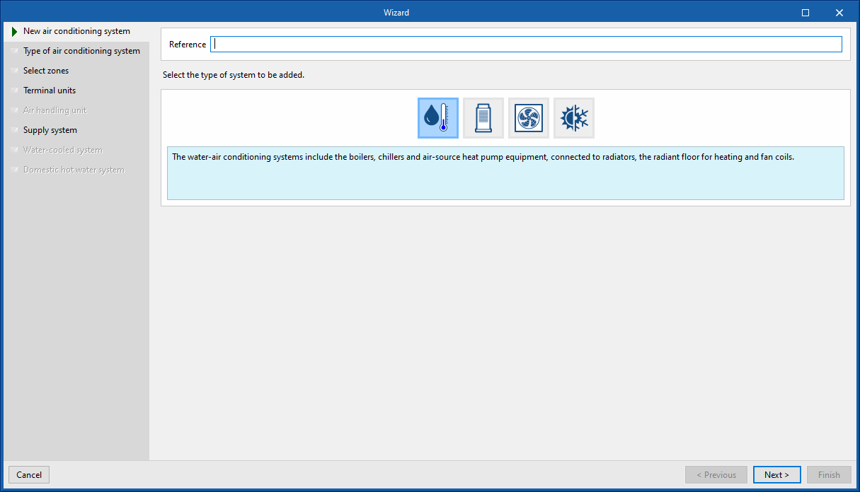
In the "Air-conditioning systems" section of the toolbar, the "Wizard" option can be used to define a complete air conditioning system, including mixed systems for air-conditioning and DHW, or to add terminal units to previously defined systems.

On the left-hand side of the window, the steps used by the wizard to guide the users to complete the definition of the air-conditioning system are shown. The different sections to be defined according to the chosen options are highlighted in black. The options displayed in the bottom bar allow users to move forwards or backwards through the wizard.
New air conditioning system
In the first window, the new system must be named and its type must be chosen between water, direct expansion, air or constant performance air-conditioning systems.
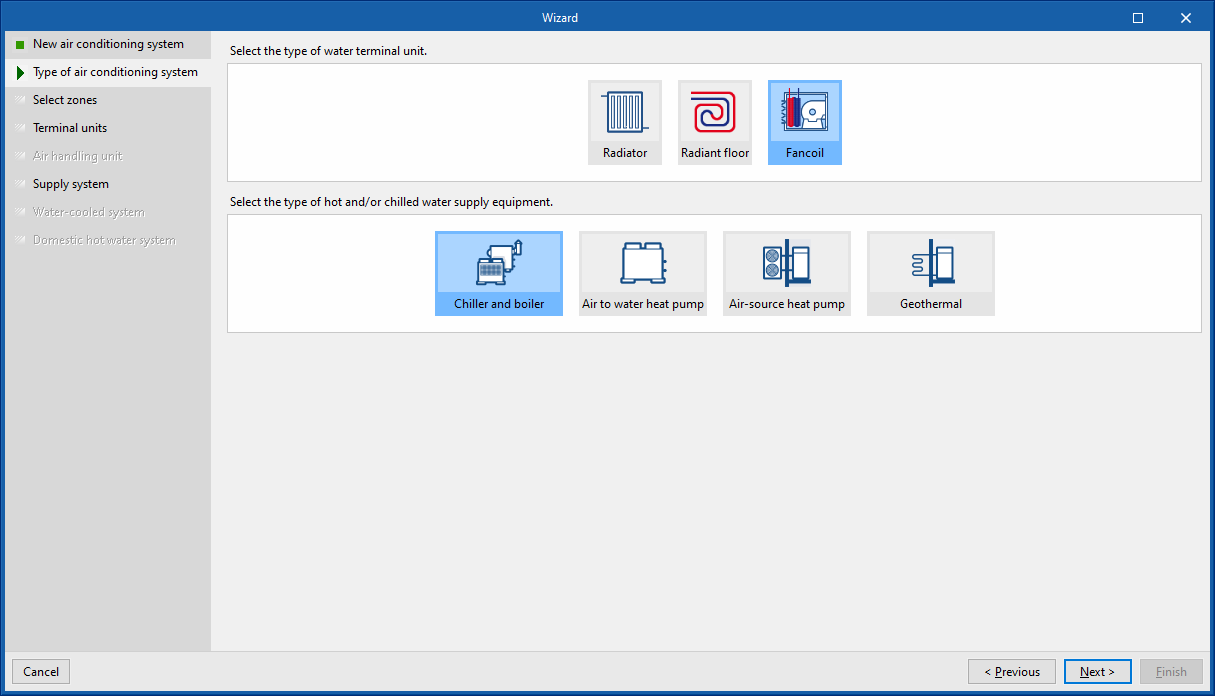
Type of air conditioning system
In the second step of the wizard, the type of air conditioning system must be selected according to the previously chosen category.
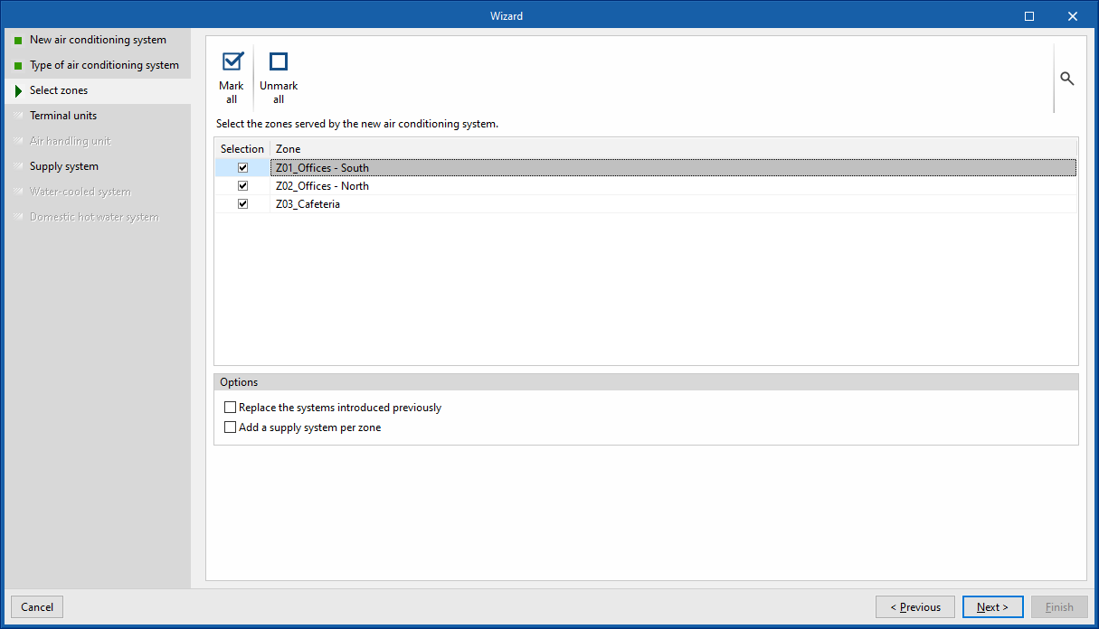
Selecting zones
In the third step, the zones of the building to be associated with the climate control system must be selected. Subsequently, the wizard automatically creates the defined system terminal units in each of the selected zones and connects them to a centralised production system if necessary. The following options are available:
- Replace the systems introduced previously
Selecting this option deletes the terminal units that already exist in the selected zones. When deleting terminal units, the air conditioning systems in the job may no longer be connected to the terminal units. In this case, when finishing, the wizard asks whether the unused systems are to be deleted. - Add a supply system per zone
Esta opción aparece en caso de haber escogido un sistema de This option appears if an air conditioning system has been chosen. If this option is selected, the number of air conditioning units will be added to the number of zones selected, each one connected to the terminal units defined in each zone. - Add a supply system per zone
If this option is chosen, the number of production units selected will be added to the number of zones selected, each one connected to the units defined in each zone. Depending on the type of system chosen, these units can be either terminal units directly or air conditioning units with water coils.
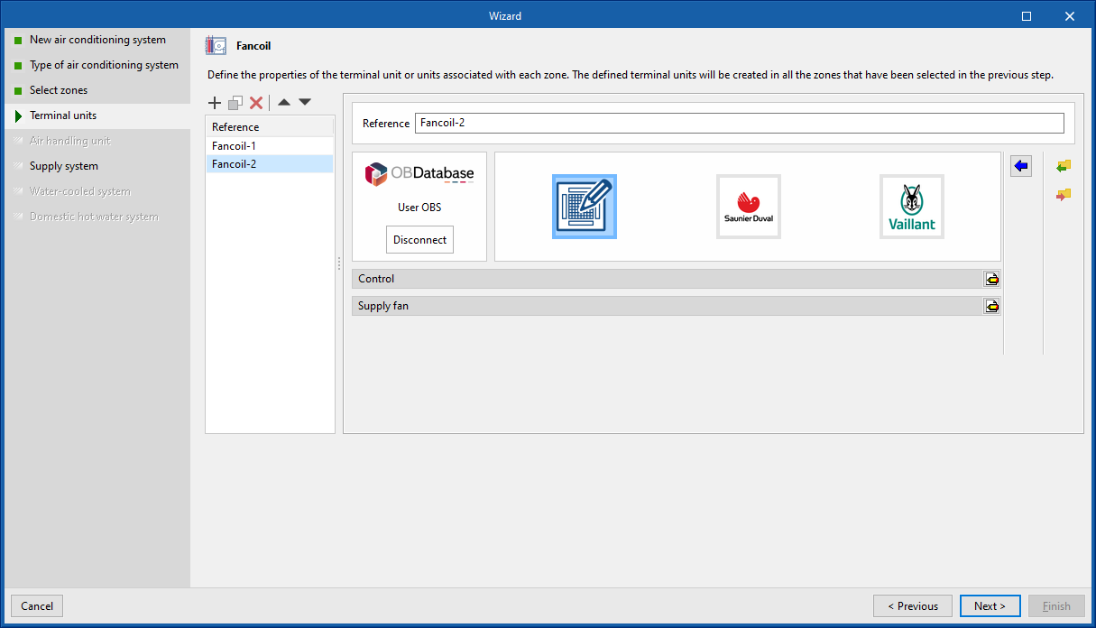
Terminal units
The next steps of the wizard are related to the different elements that make up the chosen type of air conditioning system. This is where their characteristics can be defined. In general, the definition panels corresponding to the terminal units and air conditioning systems available in the program will be displayed as required.
To describe the other options available in the wizard, the definition of a fan coil air-conditioning system connected to a water-cooled chiller and a combi boiler for heating and DHW is shown.
When defining this system, the next step offered by the wizard is the definition of fancoil-type terminal units. The terminal units defined in this step will be added to all the zones selected in the previous step. More than one terminal unit of the same type can be created in the zone using the list on the panel (depending on the combination possibilities of air conditioning systems offered by the program).
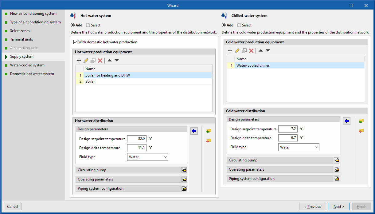
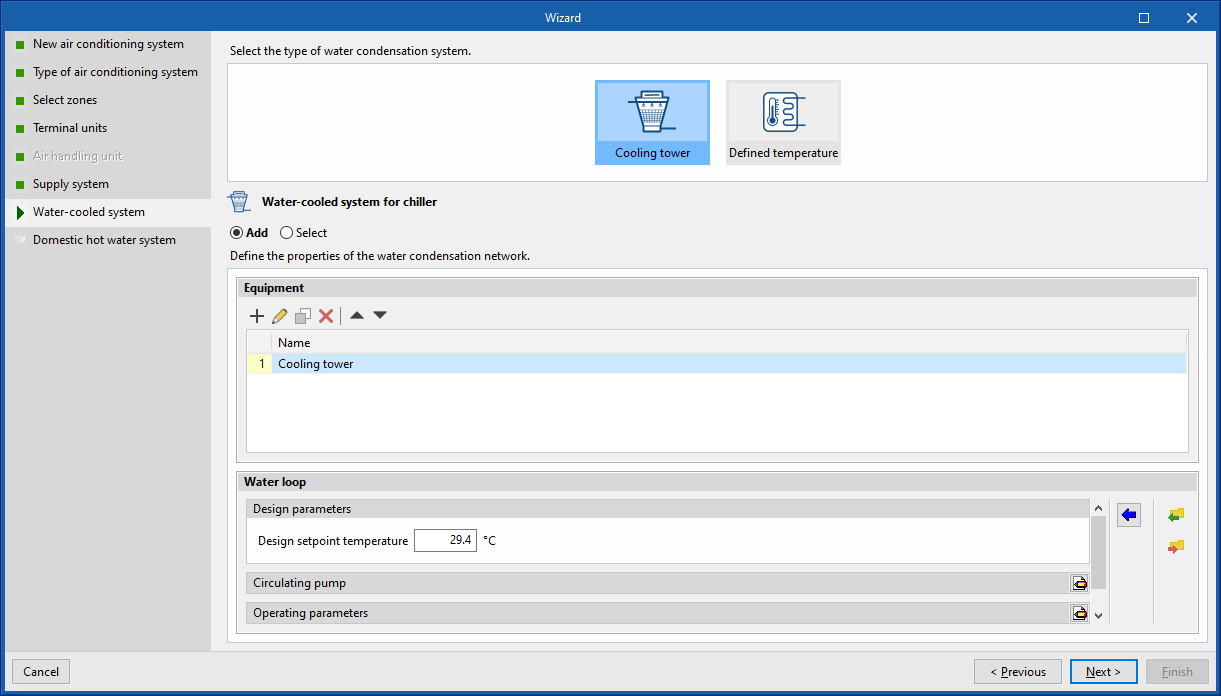
Production system / Water condensation system
The next step is to define the centralised production units (or air handling units in the case of air systems) to which the terminal units will be connected. In this example, the wizard shows the water heating and cooling systems.
The following options are available for each system:
- Add
Allows users to define a new air conditioning system. - Select
Allows users to select an air conditioning system of the corresponding type from those defined in the job. If the "Add a production system/air-conditioning unit per zone" option was selected in the third step of the wizard, a system must be added for each selected zone. - With domestic hot water production (optional)
This option is exclusive to hot water production systems ("Hot-water system" and "Air-source heat pump"). This allows users to define a combined air-conditioning and domestic hot water system.
In this example, a new hot-water system has been defined using the "With domestic hot water production" option, and a new water-cooling system containing a water-cooled condensing chiller. The wizard detects the needs of the selected units, and in the next step proposes the definition of the condensing system for the chiller.
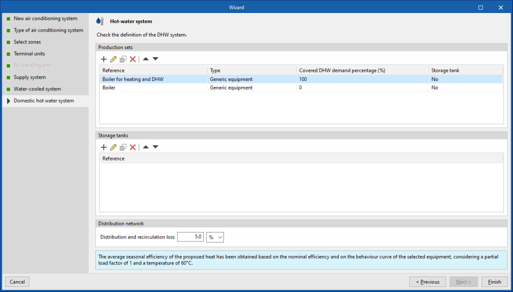
Domestic hot water system
Finally, the wizard displays the definition of the domestic hot water system to be added, based on the characteristics of the previously defined hot water production system units. If several boilers have been defined, the boiler that produces domestic hot water must be specified in order to be able to calculate its characteristics. The wizard's proposal can be accepted or edited.
When the wizard has been completed, the various elements of the defined system are added to the job layout and the necessary ventilation options are chosen at zone level.
If a DHW system has been added with the wizard, the definition depends on the selection previously made in "General parameters" for the "Daily DHW demand":
- If the "Total building demand" has been defined, the wizard creates a single DHW system for the building.
- If the "Demand by thermal zone" has been defined, the wizard creates a single DHW system by default that serves the zones selected in step 3 of the wizard. In this case, when "Add a supply system per zone" has been selected in the wizard, one DHW system is created for each zone.
Terminal unit management. Activation sequence and automatic sizing options
The "Terminal units" panel can be used to manage the operation of the terminal units defined in each zone and to define the EnergyPlus™ automatic sizing options.
Activation sequence
During this simulation, the terminal units in the zone are activated sequentially until the thermal load of the zone is overcome, according to the order defined in the "Activation sequence" sections, distinguishing between "Heating" and "Cooling".
The terminal unit responsible for the zone ventilation, if present, is always activated first.
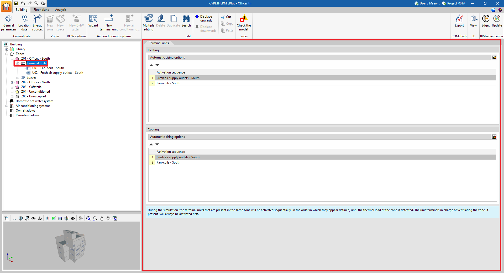
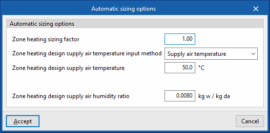
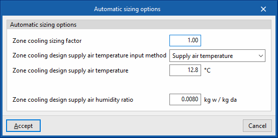
Automatic sizing options
The automatic heating/cooling sizing options are advanced features that allow users to edit the parameters that EnergyPlus™ uses to determine the characteristics of the HVAC units that have not been specified by the user (autosize function):
- Zone heating sizing factor/Zone cooling sizing factor
The scaling factor on the calculated thermal load in the zone. The capacity of the air-conditioning units is determined by the thermal load of the zone multiplied by this factor. - Zone heating design supply air temperature input method/Zone cooling design supply air temperature input method
The air flows that the units must deliver to overcome the thermal load are calculated based on a user-defined design supply temperature. Three options are available:- Supply air temperature
The design supply air temperature for heating/cooling must be defined. - Temperature jump
The temperature difference between supply air and zone temperature must be defined. - System supply air temperature
This is only valid if the zone is connected to an all-air system. The "supply air temperature" shall be taken as the supply air temperature defined as the cooling/heating design supply temperature on the panel of the air handling unit of the all-air system.
- Supply air temperature
- Zone heating design supply air humidity ratio/Zone cooling design supply air humidity ratio
For example, if there are two radiators in a heating zone and their power has not been specified, when the simulation starts, EnergyPlus™ calculates that the heating demand of the zone on the design day is equal to 1000W. In this case:
- If the "Zone heating sizing factor" equals 1, EnergyPlus™ assigns a power of 1*1000=1000 W to each radiator. In total, there will be an installed power in the zone equalling 2000 W. This means that effectively only one of the radiators is switched on, as it is already sufficient to meet the heating demand.
- If the "Zone heating sizing factor" equals 0.5, EnergyPlus™ assigns a power of 0.5*1000=500 W to each radiator. In total, there will be an installed power in the zone equalling 1000 W. The radiators will be switched on consecutively: the first one will be switched on to deliver a power of up to 500 W and, if the heating demand of the zone is higher, then the second one will be switched on.
Terminal units. Constant performance equipment
The constant performance unit can be used to represent any air-conditioning system based on its power, its seasonal average heat or cold production performance and the type of energy it consumes (energy vector). It behaves like an ideal unit, capable of instantaneously overcoming the thermal loads of the zone in which it is located (infinite power unit), totally or up to the indicated power value, thus covering the heating or cooling energy demand of the zone.
Only one constant performance equipment can be defined per zone.
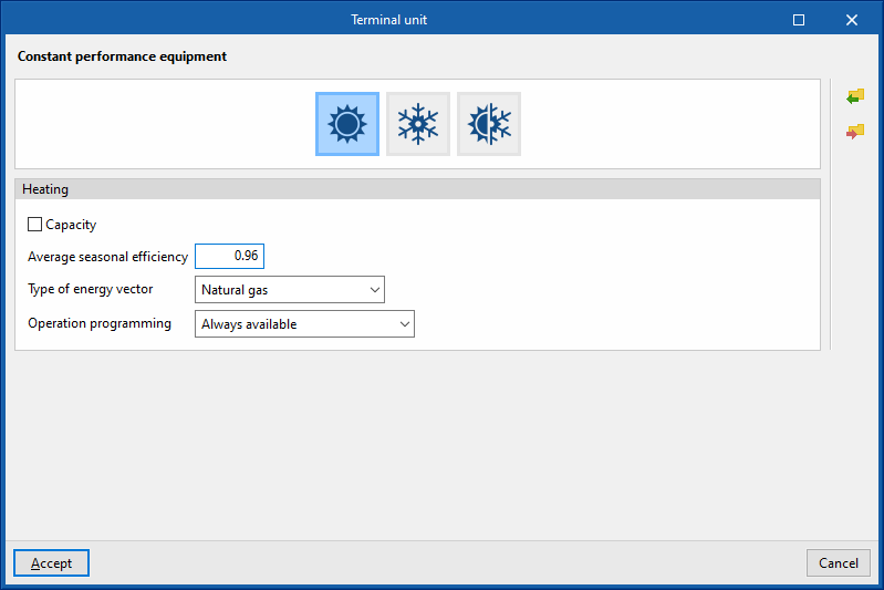
Three types of constant performance equipment are available: heating only, cooling only, and heating and cooling.
Heating
This allows users to enter constant performance equipment capable of covering the heating energy demand of the area.
- Capacity (optional)
- Average seasonal efficiency
- Type of energy vector (Electricity / Natural gas / Diesel / LPG / Coal / Biomass / Densified biomass (pellets) / Environment)
- Operation programming (Always available / With established operating time)
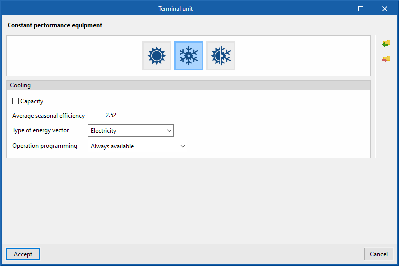
Cooling
This allows users to enter constant performance equipment capable of meeting the cooling energy demand of the area.
- Capacity (optional)
- Average seasonal efficiency
- Type of energy vector (Electricity / Natural gas / Diesel / LPG / Coal / Biomass / Densified biomass (pellets) / Environment)
- Operation programming (Always available / With established operating time)
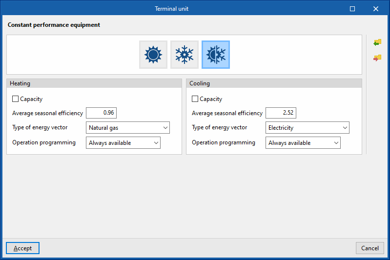
Both
This allows users to enter constant performance equipment that can cover both the heating energy demand and the cooling energy demand of the area.
Heating
- Capacity (optional)
- Average seasonal efficiency
- Type of energy vector (Electricity / Natural gas / Diesel / LPG / Coal / Biomass / Densified biomass (pellets) / Environment)
- Operation programming (Always available / With established operating time)
Cooling
- Capacity (optional)
- Average seasonal efficiency
- Type of energy vector (Electricity / Natural gas / Diesel / LPG / Coal / Biomass / Densified biomass (pellets) / Environment)
- Operation programming (Always available / With established operating time)
Terminal units. Water terminal unit
Water terminal units include radiators, radiant floor heating and fan coils, that are connected to water-based air-conditioning systems such as boilers, chillers, air-source heat pumps and geothermal units.
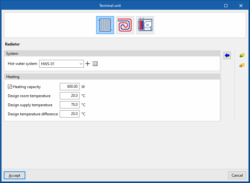
Radiator
This simulates a radiator or a set of radiators arranged in the heating zone.
System
- Water terminal unit
Allows users to select a hot-water system defined in the "Air-conditioning systems" section or to enter it directly.
Heating
- Thermal capacity (optional)
Allows users to specify a value for the thermal capacity of the radiator and for the following parameters:- Design room temperature
- Design supply temperature
- Design temperature difference
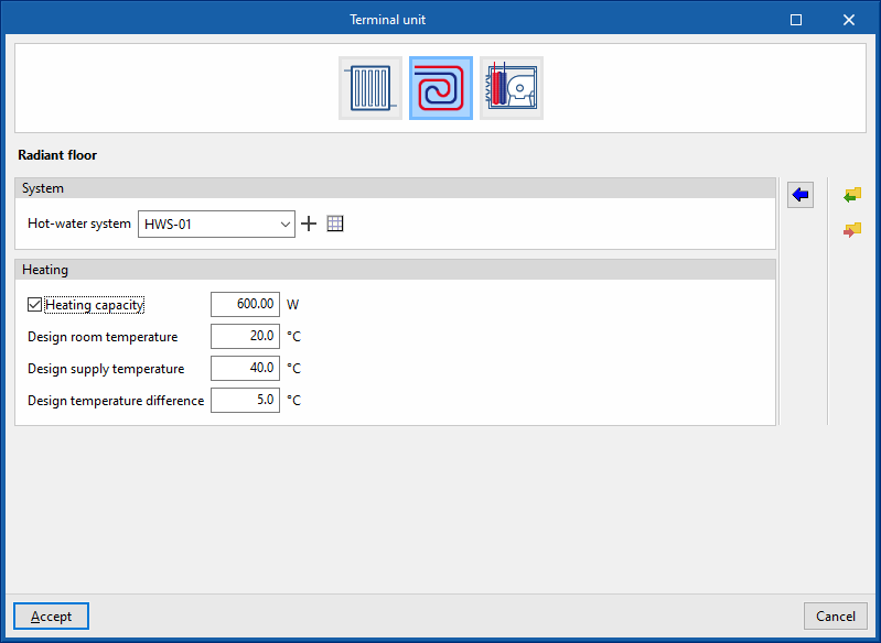
Radiant floor
This allows users to simulate radiant floor heating in the thermal zone.
System
- Hot-water system
Allows users to select a hot-water system defined in the "Air conditioning systems" section or to enter it directly.
Heating
- Heating capacity (optional)
Allows users to specify a value for the thermal power of the radiant floor and for the following parameters:- Design room temperature
- Design supply temperature
- Design temperature difference
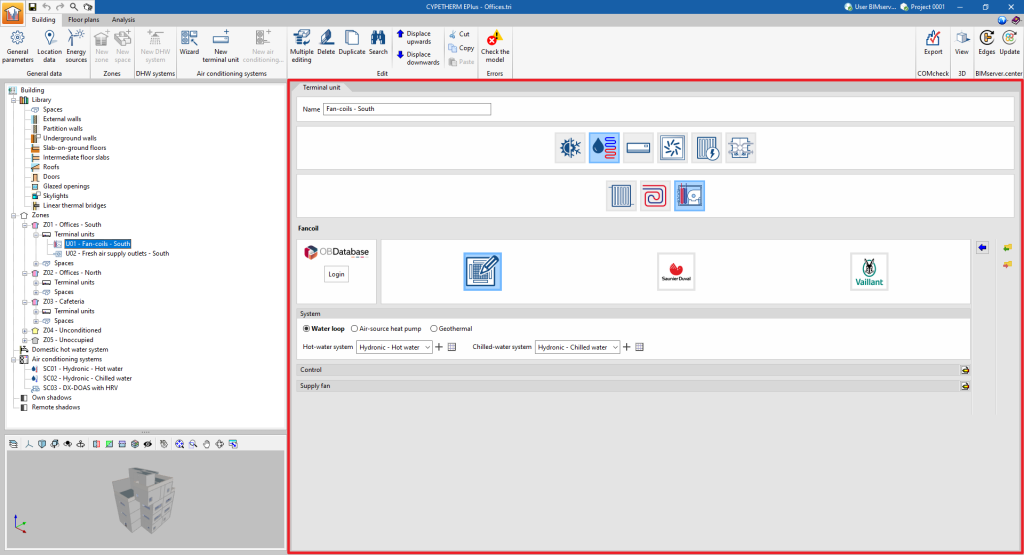
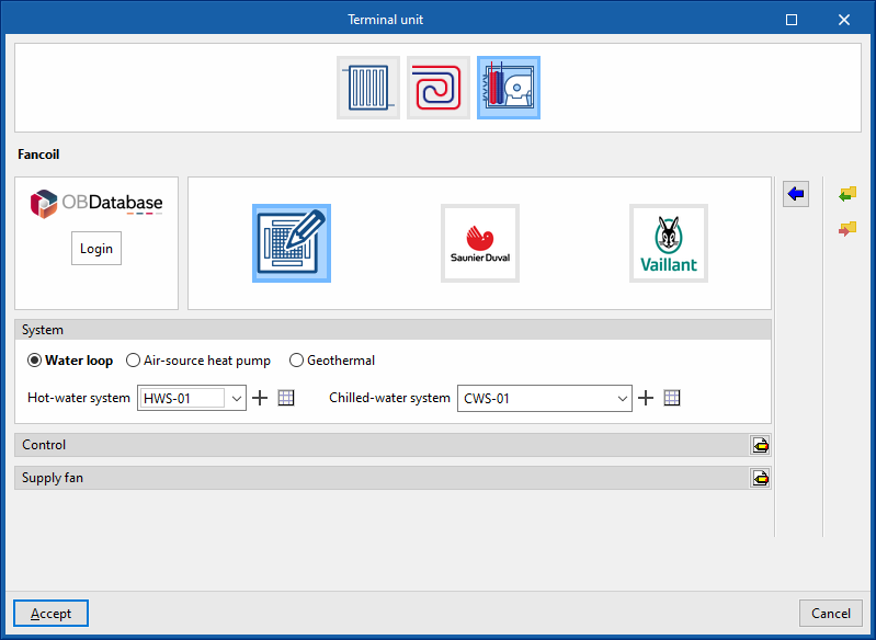
Fancoil
This terminal unit represents a 4-pipe fan coil and requires a connection to both cold and hot water.
There is no power rating specified in the definition of the fan coil. Its power depends on the flow rate and temperature of the water it receives, as well as on the airflow rate it drives.
The maximum fan coil power is limited by the "Maximum air flow rate", which is specified in the "Supply fan" definition panel.
Generic
This is used to simulate a generic fan coil or the set of generic fan coils arranged in the thermal zone.
System (Water loop / Air-source heat pump / Geothermal)
- Water loop
- Hot-water system
Allows users to select a hot-water system defined in the "Air conditioning systems" section or to enter it directly. - Chilled-water system
Allows users to select a chilled-water system defined in the "Air conditioning systems" section or to enter it directly.
- Hot-water system
- Air-source heat pump
- Air-source heat pump system
Allows users to select an air-source heat pump system defined in the "Air conditioning systems" section or to enter it directly.
- Air-source heat pump system
- Geothermal
- Geometric heat pump
Allows users to select a geometric heat pump defined in the "Air conditioning systems" section or to enter it directly.
- Geometric heat pump
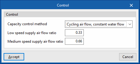
Control
The fan coil power is controlled by varying the water and/or air flow rate.
- Capacity control method (Constant air flow, variable water flow / Variable air flow, variable water flow / Cycling air flow, constant water flow / Variable air flow, constant water flow)
- Low speed supply air flow ratio
- Medium speed supply air flow ratio
- Constant air flow: the fan is a fixed speed and is always on; therefore, it heats the air when there is no demand.
- Variable air flow: the fan is of variable speed.
- Cycling air flow: the fan is 3-speed and only turns on when there is a demand.
Supply fan
- Maximum air flow rate (optional)
If the fan coil flow rate is not specified, EnergyPlus™ automatically calculates the flow rate to overcome all the loads in the zone according to the zone's "Automatic sizing options". - Specific power
- Motor efficiency
- Motor heat losses fraction in air stream

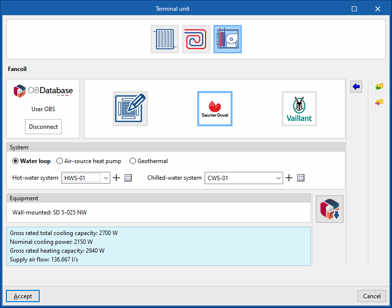
Manufacturer
This is used to simulate a manufacturer's fan coil in the thermal zone.
System (Water loop / Air-source heat pump / Geothermal)
- Water loop
- Hot-water system
Allows users to select a hot-water system defined in the "Air-conditioning systems" section or to enter it directly. - Chilled-water system
Allows users to select a chilled-water system defined in the "Air conditioning systems" section or to enter it directly.
- Hot-water system
- Air-source heat pump
- Air-source heat pump system
Allows users to select an air-source heat pump system defined in the "Air conditioning systems" section or to enter it directly.
- Air-source heat pump system
- Geothermal
- Geometric heat pump
Allows users to select a geometric heat pump defined in the "Air conditioning systems" section or to enter it directly.
- Geometric heat pump
Equipment
- Open BIM Database equipment selection
Allows users to select a fan coil from the manufacturers and models available in the Open BIM Database.
Terminal units. Direct expansion terminal units
Direct expansion terminal units include the interior units of 1x1 split systems, multisplit systems, variable refrigerant flow (VRF) systems, compact window units and water-to-air heat pumps in a closed loop.
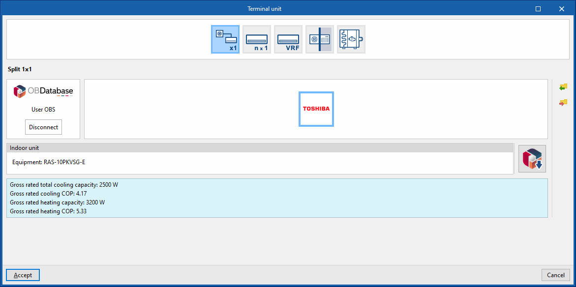
Split 1x1
This includes 1x1 split units and 1x1 ducted units. In the latter case, there is no need to simulate the duct network because all ducts must lead to the same heating zone. Furthermore, heat losses in the ducts are not considered in the program.
Manufacturer
This is used to simulate a manufacturer's 1x1 split system in the thermal zone.
Indoor unit
- Open BIM Database indoor unit selection
Allows users to select a 1x1 split indoor unit from the manufacturers and models available in the Open BIM Database.
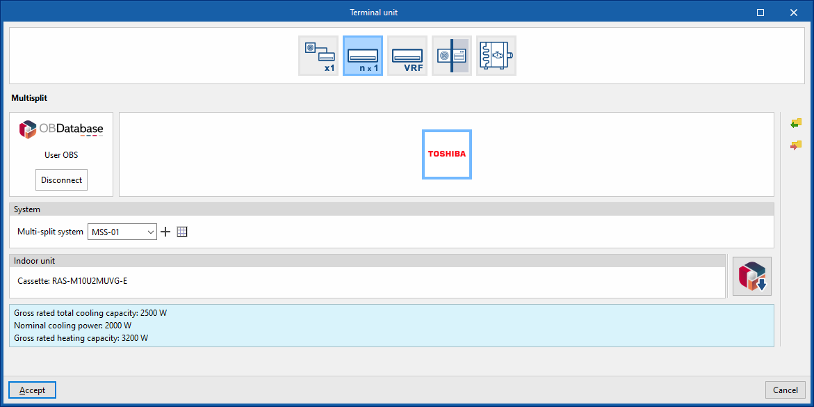
Multisplit
Manufacturer
Allows users to simulate a manufacturer's multi-split indoor unit in the thermal zone.
System
- Multisplit system
Allows users to select a multisplit system defined in the "Air conditioning systems" section or to enter it directly.
Indoor unit
- Selecting the Open BIM Database indoor unit
Allows users to select a multisplit indoor unit from the manufacturers and models available in the Open BIM Database.
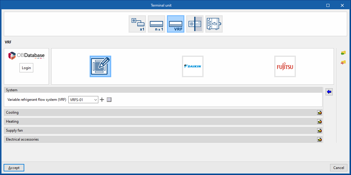
Variable refrigerant flow (VRF)
Generic
This allows users to simulate an indoor unit of a generic variable refrigerant flow system placed in the thermal zone.
System
- VRF
Allows users to select a VRF system defined in the "Air conditioning systems" section or to enter it directly.
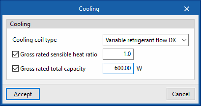
Cooling
- Cooling coil type (Variable refrigerant flow / None)
Sets the characteristics of the cooling coil:- Variable refrigerant flow
- Gross rated sensible heat ratio (optional)
- Gross rated total capacity (optional)
- Variable refrigerant flow
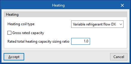
Heating
- Heating coil type (Variable refrigerant flow / None)
Sets the characteristics of the heating coil:- Variable refrigerant flow
- Gross rated capacity (optional)
- Rated total heatinc capacity sizing ratio
- Variable refrigerant flow
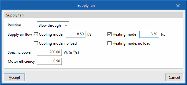
Supply fan
- Position (Blow through / Draw through)
- Supply air flow
- Cooling mode (optional)
- Cooling mode, no load (optional)
- Heating mode (optional)
- Heating mode, no load (optional)
- Specific power
- Motor efficiency
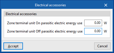
Electrical accessories
- Zone terminal unit On parasitic electric energy use
- Zone terminal unit Off parasitic electric energy use
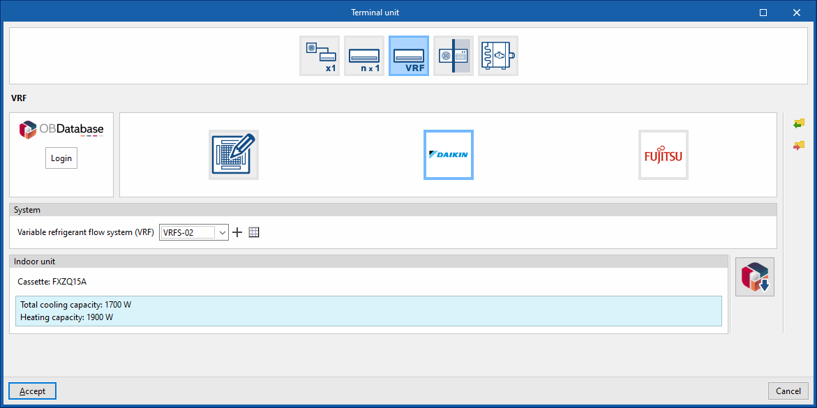
Manufacturer
This is used to simulate an indoor unit of a manufacturer's variable refrigerant flow system in the thermal zone.
System
- Variable refrigerant flow system (VRF)
Allows users to select a variable refrigerant flow rate system defined in the "Air conditioning systems" section or enter it directly.
Indoor unit
- Open BIM Database indoor unit selection
Allows users to select an indoor unit of a variable refrigerant flow system from the manufacturers and models available in the Open BIM Database.
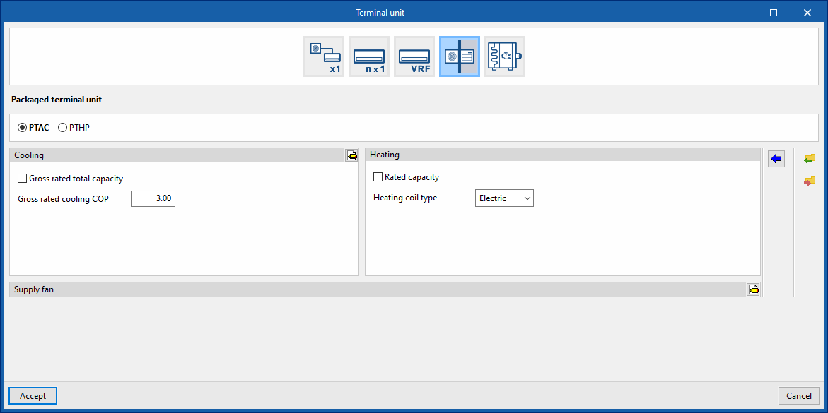
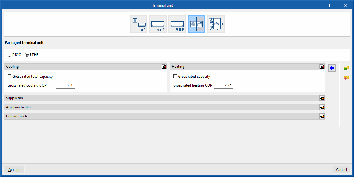
Packaged terminal unit
This allows users to simulate packaged window terminal units arranged in the thermal zone.
PTAC
Cooling
- Gross rated total capacity (optional)
- Nominal cooling COP
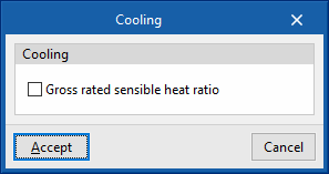
- Advanced configuration
- Gross rated sensible heat ratio
Heating
- Gross rated capacity (optional)
- Heating coil type (Electrical / Hot water / Gas)
This sets the characteristics of the heating coil:- Electrical
- Hot water
- Hot-water system
Allows users to select a water heating system defined in the "Air conditioning systems" section or to enter it directly.
- Hot-water system
- Gas
- Gas heating coil efficiency
- Parasitic electric load
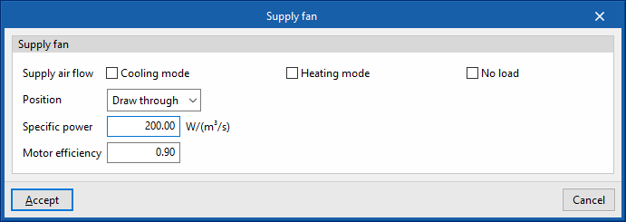
Supply fan
- Supply air flow
- Cooling mode (optional)
- Heating mode (optional)
- No load (optional)
- Position (Blow through / Draw through)
- Specific power
- Motor efficiency
PTHP
Cooling
- Gross rated total capacity (optional)
- Nominal cooling COP
- Advanced configuration
- Gross rated sensible heat ratio
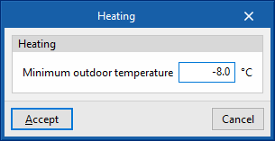
Heating
- Gross rated capacity (optional)
- Gross rated heating COP
- Advanced configuration
- Minimum outdoor temperature

Supply fan
- Supply air flow
- Cooling mode (optional)
- Heating mode (optional)
- No load (optional)
- Position (Blow through / Draw through)
- Specific power
- Motor efficiency

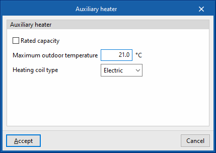
Auxiliary heater
- Gross rated capacity (optional)
- Maximum outdoor temperature
- Heating coil type (Electrical / Hot water / Gas)
Sets the characteristics of the heating coil:- Electric
- Hot water
- Hot-water system
Allows users to select a water heating system defined in the "Air conditioning systems" section or to enter it directly.
- Hot-water system
- Gas
- Gas heating coil efficiency
- Parasitic electric load
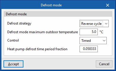
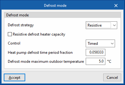
Defrost mode
- Defrost strategy (Resistive / Reverse cycle)
- Resistive defrost heater capacity
- Defrost mode maximum outdoor temperature
- Control (Timed / On demand)
- Heat pump defrost time period fraction
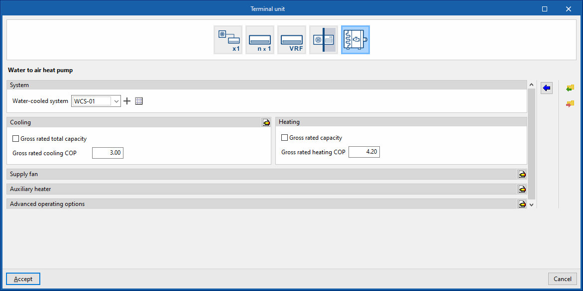
Water to air heat pump
System
- Water-cooled system
Allows users to select a water-cooled system defined in the "Air conditioning systems" section or to enter it directly.
Cooling
- Gross rated total capacity (optional)
- Nominal cooling COP
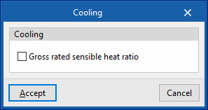
- Advanced configuration
- Gross rated sensible heat ratio
Heating
- Gross rated capacity (optional)
- Gross rated heating COP
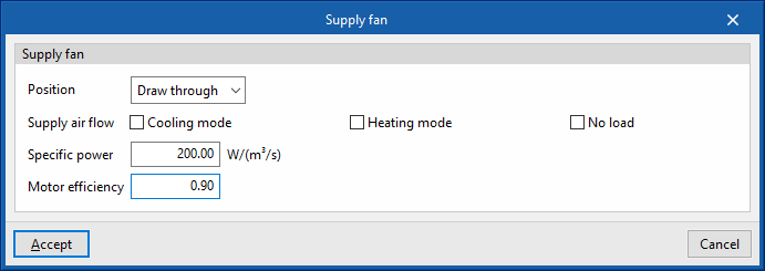
Supply fan
- Position (Blow through / Draw through)
- Supply air flow
- Cooling mode (optional)
- Heating mode (optional)
- No load (optional)
- Specific power
- Motor efficiency
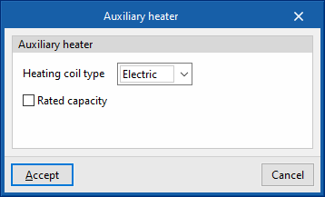
Auxiliary heater
- Heating coil type (Electric / Hot water)
Sets the characteristics of the heating coil:- Electric
- Gross rated capacity (optional)
- Hot water
- Hot-water system
Allows users to select a water heating system defined in the "Air conditioning systems" section or to enter it directly.
- Hot-water system
- Electric
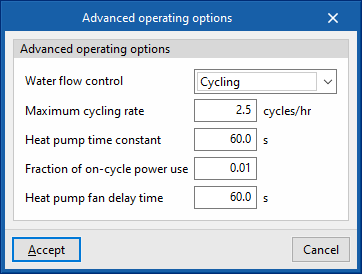
Advanced operating options
- Water flow control (Constant / Cycling / Constant on demand
- Maximum cycling rate
- Heat pump time constant
- Fraction of on-cycle power use
- Heat pump fan delay time
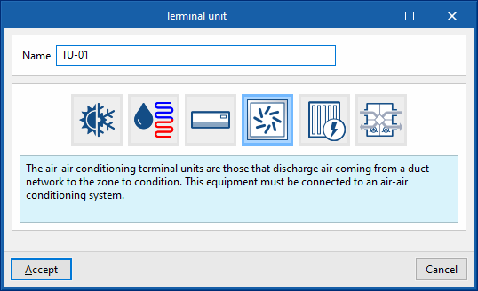
Terminal units. Air terminal unit
Air terminal units represent the supply air terminals (diffusers, grilles, nozzles, etc.) into which the ducts of the all-air systems flow.
In the program, these must be connected to an air conditioning system (such as an air handling unit), depending on their type.
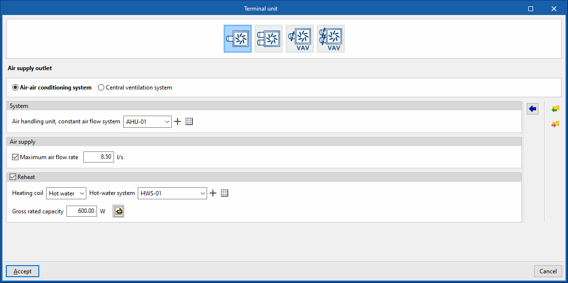
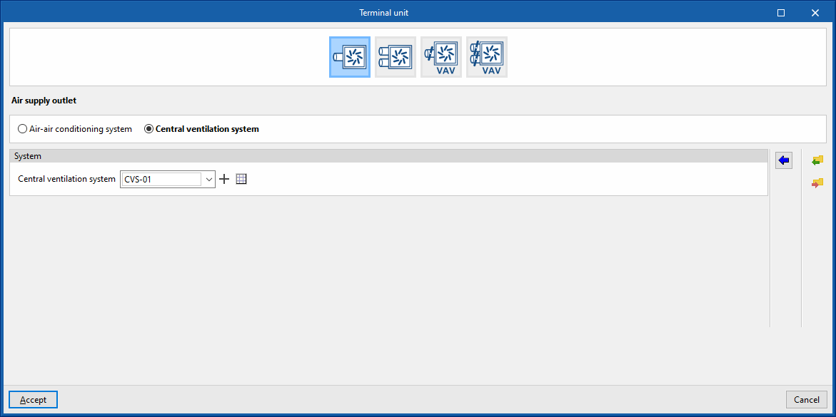
Air supply outlet
This terminal unit represents an air supply terminal connected to a constant air flow system, or a centralised ventilation system, depending on the option chosen.
Air-air conditioning system
System
- Air handling unit, constant air flow system
Allows users to select an air handling unit, constant air flow system defined in the "Air conditioning systems" section or to enter it directly.
Air supply
- Maximum air flow rate (optional)
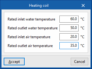
Reheat (optional)
- Heating coil (Hot water / Electric / Gas)
Sets the characteristics of the heating coil:- Hot water
- Hot-water system
Allows users to select a water heating system defined in the "Air conditioning systems" section or to enter it directly. - Gross rated capacity
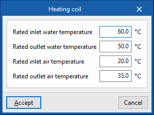
- Advanced configuration
- Rated inlet water temperature
- Rated outlet water temperature
- Rated inlet air temperature
- Rated outlet air temperature
- Hot-water system
- Electric
- Gross rated capacity
- Gas
- Gross rated capacity
- Hot water
Central ventilation system
System
- Central ventilation system
Allows users to select a central ventilation system defined in the "Air conditioning systems" section or to enter it directly.
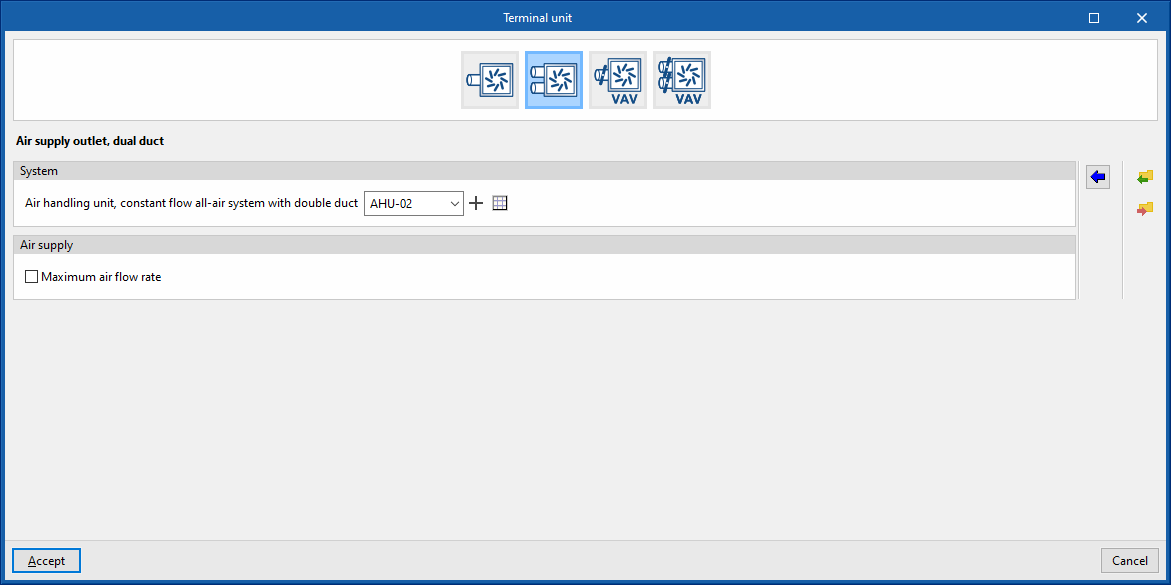
Air supply outlet, dual duct
This terminal unit represents an air supply outlet connected to a dual-duct, constant flow, all-air system.
System
- Air handling unit, constant flow all-air system with double duct
Allows users to select an air handling unit, constant flow all-air system with double duct central ventilation system defined in the "Air conditioning systems" section or to enter it directly.
Air supply
- Maximum air flow rate (optional)
Variable air volume box
This terminal unit represents a variable air volume box connected to a dual-duct, constant flow, all-air system.
System
- Air handling unit, variable airflow system
Allows users to select an air handling unit, variable airflow system defined in the "Air conditioning systems" section or to enter it directly.
Air supply
- Maximum air flow rate (optional)
- Minimum air flow fraction (optional)
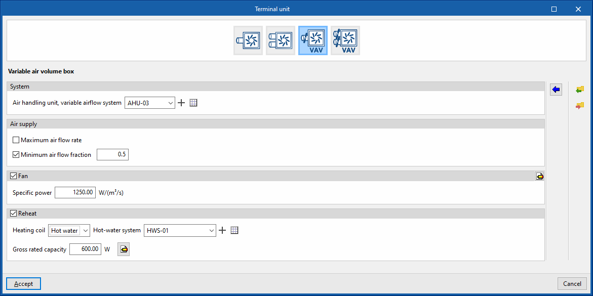
Fan (optional)
- Specific power
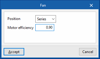
- Advanced configuration
- Position (Series / Parallel)
- Series
- Motor efficiency
- Parallel
- Motor efficiency
- Fraction of airflow to activate the fan
- Series
- Position (Series / Parallel)
Reheat (optional)
- Heating coil (Hot water / Electric / Gas)
Sets the characteristics of the heating coil:- Hot water
- Hot-water system
- Gross rated capacity
- Advanced configuration
- Rated inlet water temperature
- Rated outlet water temperature
- Rated inlet air temperature
- Rated outlet air temperature
- Electric
- Gross rated capacity
- Gas
- Gross rated capacity
- Hot water
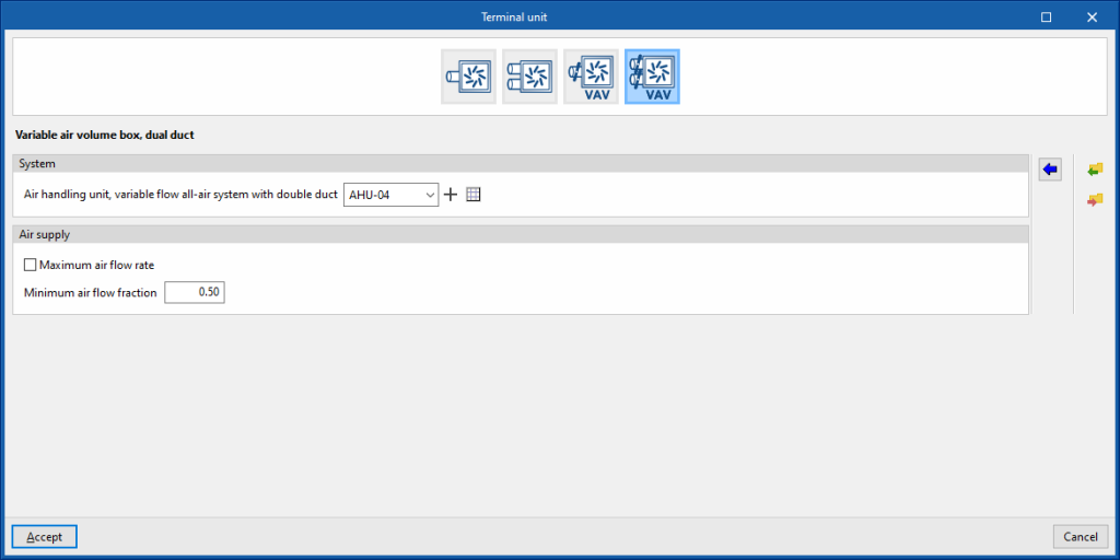
Variable air volume box, dual duct
This terminal unit represents a variable air volume box connected to a dual-duct, constant flow, all-air system.
System
- Air handling unit, variable flow all-air system with double duct
Allows users to select an air handling unit, variable flow all-air system with double duct defined in the "Air conditioning systems" section or to enter it directly.
Air supply
- Maximum air flow rate (optional)
- Minimum air flow fraction
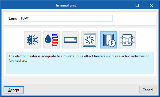
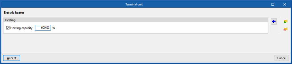
Terminal units. Electric heater
This terminal unit represents the electric heating units in the zone (Joule heating), such as electric radiators or fan heaters.
Heating
- Heating capacity (optional)
Allows users to specify a value for the heating capacity of the electric heater.
Terminal units. Heat recovery unit
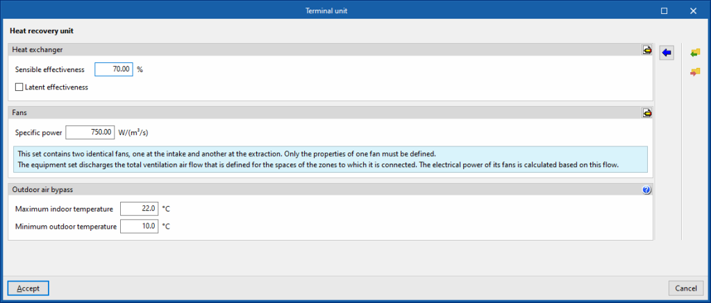
This terminal unit represents a heat recovery unit in the thermal zone.
Heat exchanger
- Sensible effectiveness
- Latent effectiveness (optional)
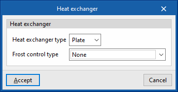
- Advanced configuration
- Heat exchanger type (Plate / Rotary)
- Frost control type (None / Exhaust air recirculation / Exhaust only / Minimum exhaust temperature)
Fans
- Specific power
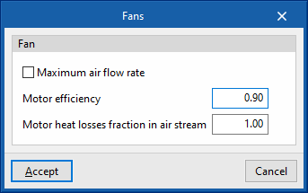
- Advanced configuration
- Maximum air flow rate (optional)
- Motor efficiency
- Motor heat losses fraction in air stream
The unit drives the total ventilation airflow defined in the spaces of the zones to which it is connected. The electrical power of its fans is calculated according to this flow rate.
Outdoor air bypass
- Maximum indoor temperature
- Minimum outdoor temperature
- The indoor temperature is greater than the maximum indoor temperature.
- The outdoor temperature is greater than the minimum outdoor temperature.
- The outdoor temperature is less than the indoor temperature.
Water-air conditioning systems
Water-based air-conditioning systems include units such as boilers, chillers and air-source heat pump units, as well as the hot or cold water distribution network. Terminal units that may be connected to these systems include radiators, radiant floor heating and fan coils.
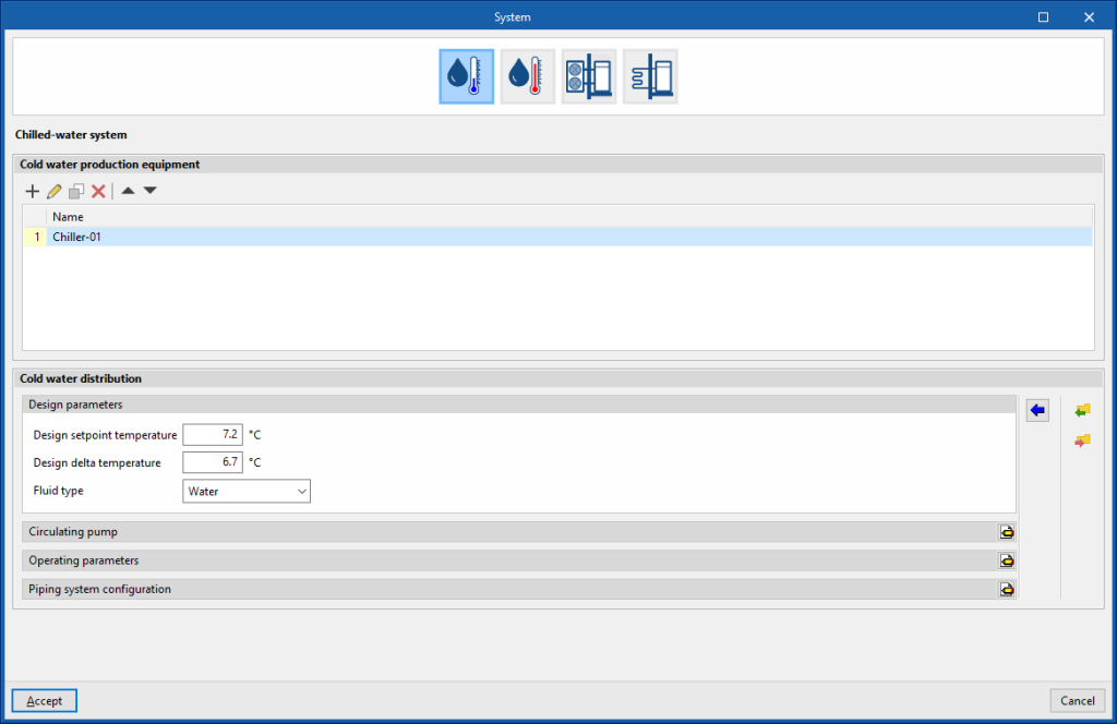
Chilled-water system
The definition of chilled-water systems is presented in two sections: "Cold water production equipment" and "Cold water distribution".
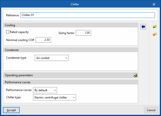
Cold water production equipment (chillers)
This section defines the cold water production equipment (chillers) connected in parallel to the cold water distribution network. A maximum of 10 units can be used.
- Reference
Reference of the unit. - Cooling
- Gross rated capacity (optional)
- Sizing factor
If the users do not define a power value, the power of the unit will be determined from the heat load of the zone multiplied by this factor.
- Sizing factor
- Nominal cooling COP
- Gross rated capacity (optional)
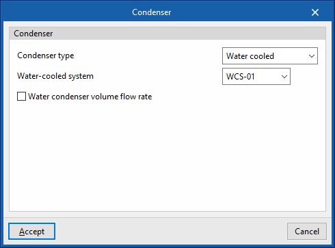
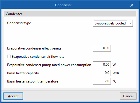
- Condenser
- Condenser type (Air cooled / Water cooled / Evaporatively cooled)
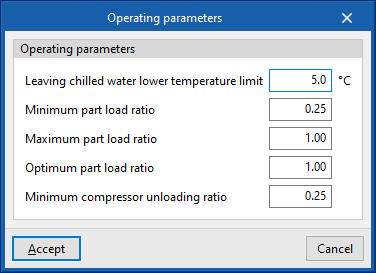
- Operating parameters
- Leaving chilled water lower temperature limit
- Minimum part load ratio
This is the ratio between the minimum power and the gross rated capacity of the unit. Below this load value, the unit operates by switching on and off. - Maximum part load ratio
This is the ratio between the minimum power and the gross rated capacity of the unit. If it is greater than 1, the unit can cover loads above its gross rated capacity. - Optimum part load ratio
This is the ratio between the power that the unit can develop and the gross rated capacity that ensures a higher efficiency. This data only applies if there is more than one unit and, in the "Operating parameters", the loads are to be distributed taking into account this optimum ratio. - Minimum compressor unloading ratio
- Performance curves
- Default
- Electric centrifugal chiller / Electric screw chiller / Electric reciprocating chiller
- User-defined
- Default
Cold water distribution
This section defines the design and operating parameters of the cold water distribution network as well as the circulation pump.
- Design parameters
These parameters are used to automatically calculate the flow rate of the cold water circuit.- Design setpoint temperature
- Design delta temperature
- Type of fluid (Water / Ethylene glycol / Propylene glycol)
- Circulating pump
- Control (Intermittent / Continuous)
- Intermittent
If the control is intermittent, the pump is switched on and off at the same time as the system. - Continuous
If the control is continuous, the pump is always on, even if there is no demand. In long periods of no demand, heat losses from the pump accumulate in the fluid, which can cause a significant rise in its temperature.
- Intermittent
- Configuration (Constant primary no secondary / Variable primary no secondary / Constant primary variable secondary)
- Primary loop pump type (Single pump / Pump per chiller / Two headered pumps / Three headered pumps / Four headered pumps / Five headered pumps)
- Primary loop pump rated head
- Control (Intermittent / Continuous)
- Operating parameters
- Minimum outdoor temperature
Below this temperature value, the production units do not switch on even if there is demand in the zones. - Load distribution scheme (Optimal / Sequential load / Uniform load / Uniform PLR / Sequential uniform PLR)
This allows users to control the activation of the production units.- Optimal
The units share the load sequentially until the optimum partial load ratio (PLR) indicated for each generator is reached. - Sequential load
The devices are switched on successively, in the order listed, until the load has expired. - Uniform load
The units share the load equally. - Uniform PLR
The units share the load proportionally to their gross rated capacity. - Sequential uniform PLR
This determines how many devices are needed to overcome the load, and the load is distributed among them in proportion to their gross rated capacity. The rest of the units remain switched off.
- Optimal
- Setpoint temperature control (Design setpoint temperature / Outdoor air temperature reset)
During the simulation, the setpoint temperature indicated in this section shall be used.
- Minimum outdoor temperature
- Piping system configuration
The bypass pipes are used to regulate the power of the circuit in the simulation. They function as valves in a real installation. These options should not be deactivated.- Supply side bypass pipe (optional)
- Demand side bypass pipe (optional)


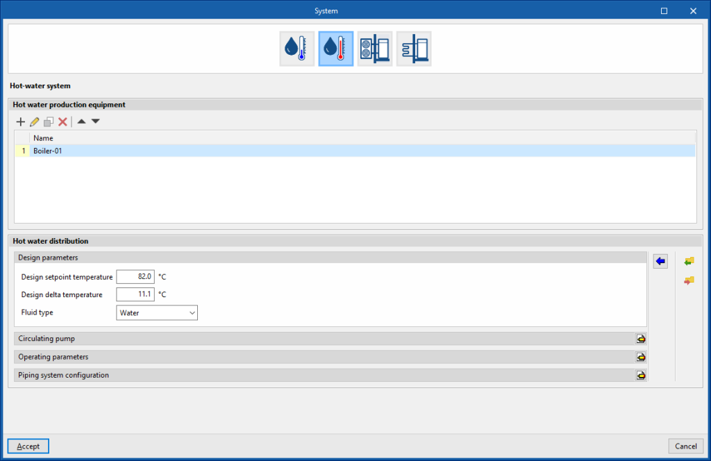
Hot-water system
There are two sections in the definition of water heating systems: "Hot water production equipment" and "Hot water distribution".
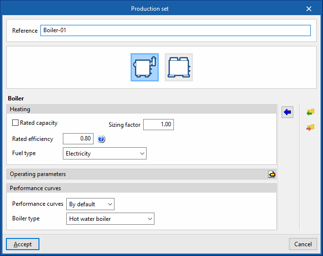
Hot water production equipment
This section defines the hot water production units connected in parallel to the hot water distribution network. A maximum of 10 units can be provided.
Boiler
- Reference
Reference of the unit. - Heating
- Gross rated capacity (optional)
Allows users to specify a value for the gross rated capacity of the boiler.- Sizing factor
If no power value has been defined, the power of the equipment shall be determined from the heat load of the zone multiplied by this factor.
- Sizing factor
- Rated efficiency
If the performance curve is not defined, the efficiency value of the boiler measured at the following nominal conditions must be given:- Conventional boiler: water outlet at 82°C / Condensing boiler: water inlet at 70°C.
- Fuel type (Electricity / Natural gas / LPG / Diesel / Coal / Biomass / Densified biomass (pellets))
- Gross rated capacity (optional)
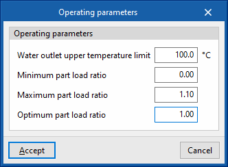
- Operating parameters
- Water outlet upper temperature limit
- Minimum part load ratio
This is the ratio between the minimum power and the gross rated capacity of the unit. Below this load value, the unit operates by switching on and off. - Maximum part load ratio
This is the ratio between the minimum power and the gross rated capacity of the unit. If it is greater than 1, the unit can cover loads above its gross rated capacity. - Optimum part load ratio
This is the ratio between the power that the unit can develop and the gross rated capacity that ensures a higher efficiency. This data only applies if there is more than one unit and, in the "Operating parameters", the loads are to be distributed taking into account this optimum ratio.
- Performance curves
- Default
- Conventional boiler / Condensing boiler
- User-defined
- Default
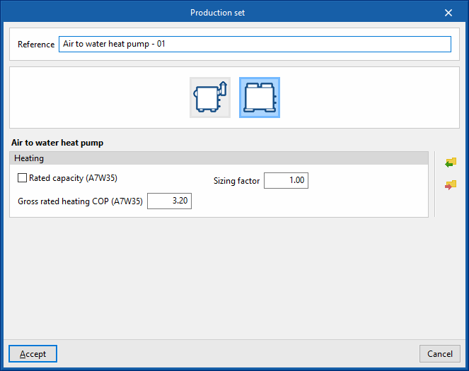
Air to water heat pump
- Reference
Reference of the unit. - Heating
- Gross rated capacity (A7W35) (optional)
Allows users to specify a value for the gross rated capacity of the air-to-water heat pump.- Sizing factor
If no power value has been defined, the power of the equipment shall be determined from the heat load of the zone multiplied by this factor.
- Sizing factor
- Gross rated heating COP (A7W35)
- Gross rated capacity (A7W35) (optional)
Hot water distribution
This section defines the design and operating parameters of the hot water distribution network as well as the circulating pump.
- Design parameters
These parameters are used to automatically calculate the flow rate of the hot water circuit.- Design setpoint temperature
- Design delta temperature
- Type of fluid (Water / Ethylene glycol / Propylene glycol)
- Circulating pump
- Control (Intermittent / Continuous)
- Intermittent
If the control is intermittent, the pump is switched on and off at the same time as the system. - Continuous
If the control is continuous, the pump is always on, even if there is no demand. In long periods of no demand, heat losses from the pump accumulate in the fluid, which can cause a significant rise in its temperature.
- Intermittent
- Configuration (Variable flow / Constant flow)
- Primary loop pump type (Single pump / Pump per chiller / Two headered pumps / Three headered pumps / Four headered pumps / Five headered pumps)
- Rated head
- Control (Intermittent / Continuous)
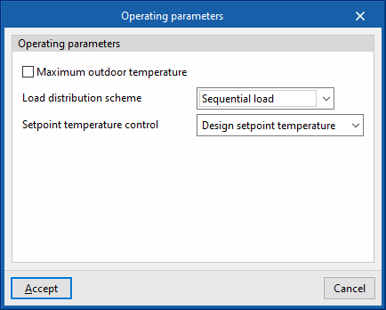
- Operating parameters
- Maximum outdoor temperature
Above this temperature value, the production units do not switch on even if there is demand in the zones. - Load distribution scheme (Optimal / Sequential load / Uniform load / Uniform PLR / Sequential uniform PLR)
This allows the activation of production equipment to be controlled.- Optimal
The units share the load sequentially until the optimum partial load ratio (PLR) indicated for each generator is reached. - Sequential load
The devices are switched on successively, in the order listed, until the load has expired. - Uniform load
The units share the load equally. - Uniform PLR
The units share the load proportionally to their gross rated capacity. - Sequential uniform PLR
This determines how many devices are needed to overcome the load, and the load is distributed among them in proportion to their gross rated capacity. The rest of the units remain switched off.
- Optimal
- Setpoint temperature control (Design setpoint temperature / Outdoor air temperature reset)
During the simulation, the setpoint temperature indicated in this section shall be used.
- Maximum outdoor temperature
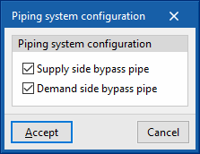
- Piping system configuration
The bypass pipes are used to regulate the power of the circuit in the simulation. They function as valves in a real installation. These options should not be deactivated.- Supply side bypass pipe (optional)
- Demand side bypass pipe (optional)

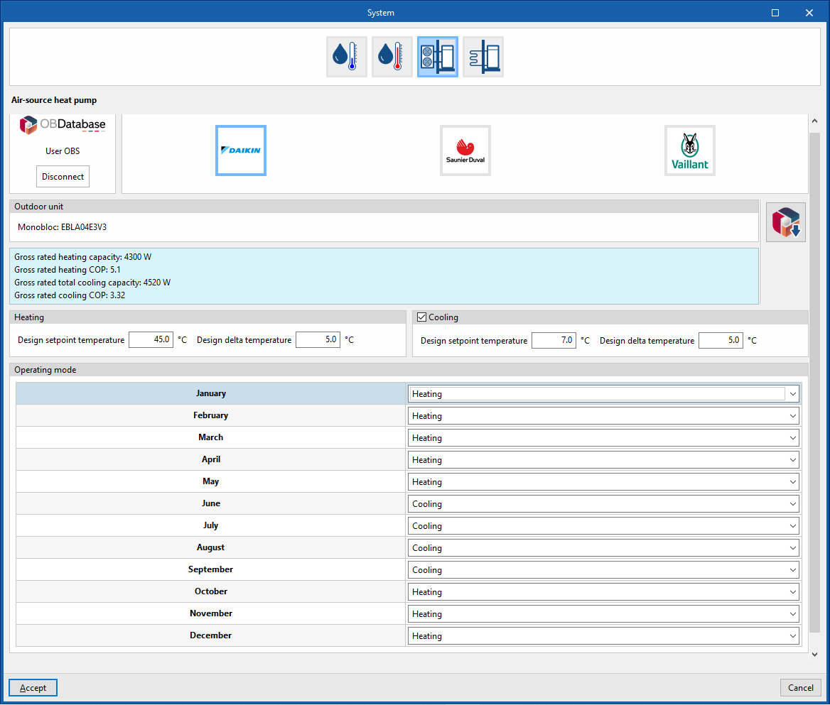
Air-source heat pump system
Manufacturer
Aerothermal
- Open BIM Database unit selection
Allows users to select an aerothermal system from the manufacturers and models available in the Open BIM Database.
Heating
These parameters are used to automatically calculate the flow rate of the water circuit.
- Design setpoint temperature
- Design delta temperature
Cooling (optional depending on the model)
These parameters are used to automatically calculate the flow rate of the water circuit.
- Design setpoint temperature
- Design delta temperature
Operating mode (monthly)
- Heating / Cooling (optional) / Off
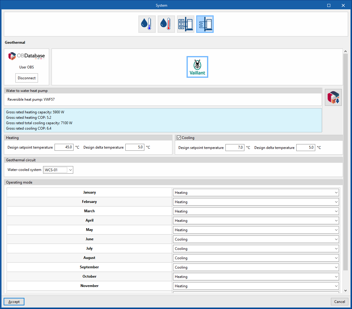
Geometric heat pump
Manufacturer
Geothermal
- Open BIM Database equipment selection
Allows users to select a geothermal heat pump from the manufacturers and models available in the Open BIM Database.
Heating
These parameters are used to automatically calculate the flow rate of the water circuit.
- Design setpoint temperature
- Design setpoint temperature
Cooling (optional depending on model)
These parameters are used to automatically calculate the flow rate of the water circuit.
- Design setpoint temperature
- Design setpoint temperature
Geothermal circuit
Allows users to select a water condensation system at a defined temperature entered in the "Air conditioning systems" section.
- Water-cooled system
Operating mode (monthly)
- Heating / Cooling (optional) / Off
Performance curves
The behaviour of heating and cooling units varies depending on the operating conditions. CYPETHERM energy simulation programs using the EnergyPlus™ calculation engine can consider this variation in two ways:
- By selecting the default performance curves included for each unit. To do this, the “Default” option is selected when editing the performance curves of the unit.
- By editing the performance curves of the hydronic production units (boilers and chillers). To do this, the ‘User-defined’ option is selected when editing the performance curves of the unit. There are two options for entering this data in the program: in the form of a table or in the form of a polynomial curve.
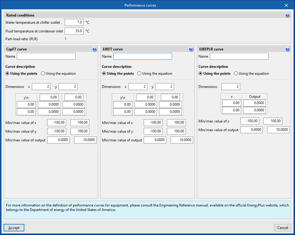
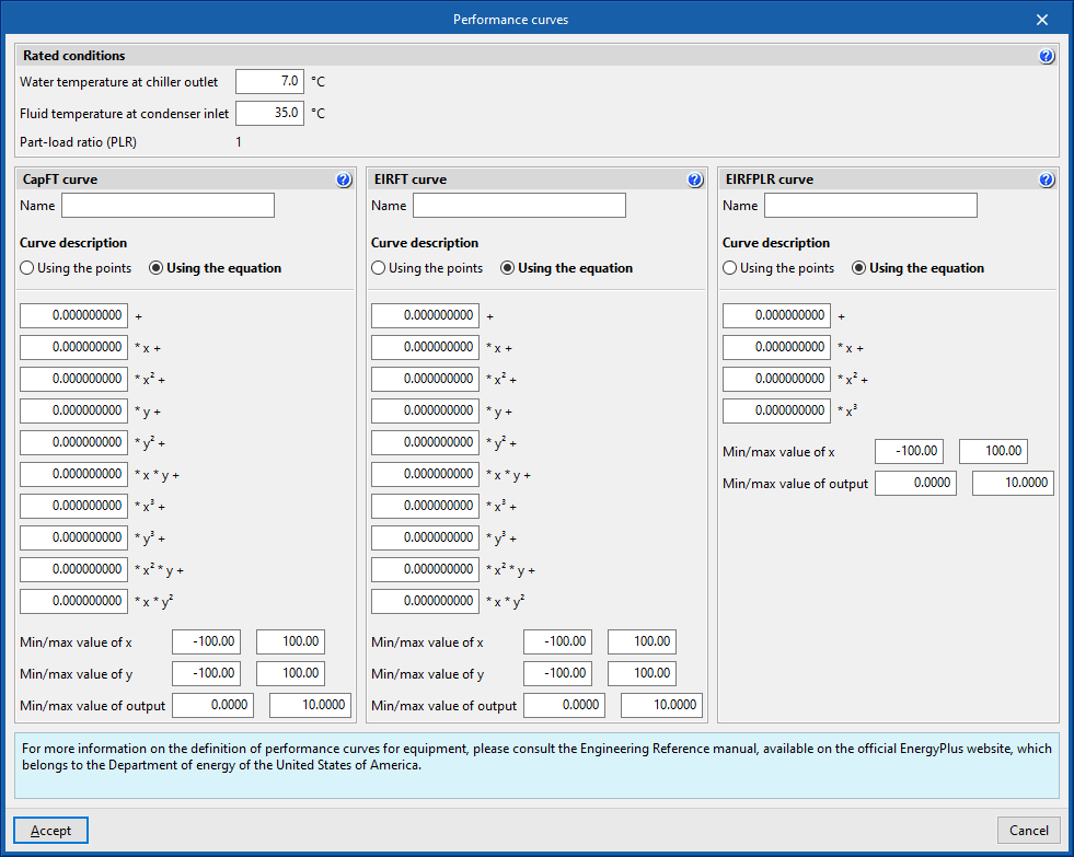
User-defined performance curves for chillers
Rated conditions
Rated conditions are the operating conditions under which the rated characteristics of the units are defined.
The performance curves must be defined in such a way that under rated conditions their value is equal to 1.
All performance curves for the same units must be defined for the same rated conditions.
- Water temperature at chiller outlet
- Fluid temperature at condenser inlet
CapFT curve
Cooling power correction coefficient.
EIRFT curve
Electricity consumption correction factor.
x: Water temperature at chiller outlet (°C)
y: Fluid temperature at condenser inlet (°C)
Depending on the option selected in "Condenser type", the temperature of the fluid at the inlet of the condenser is referred to:
- Water cooled: Water temperature.
- Air cooled: Air dry bulb temperature.
- Evaporative cooling: Air wet bulb temperature.
EIRFPLR curve
Electricity consumption correction factor.
- x: Part-load ratio (PLR)
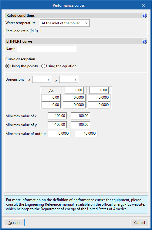
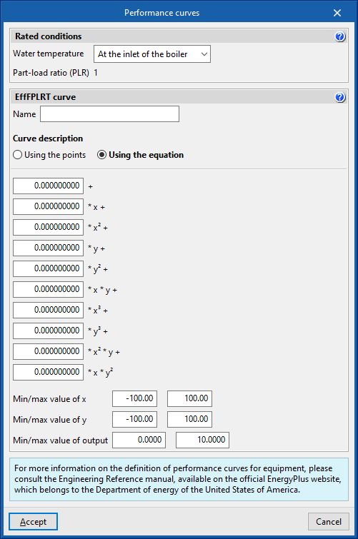
User-defined performance curves for boilers
Rated conditions
Rated conditions are the operating conditions under which the rated characteristics of the units are defined.
The performance curves must be defined in such a way that under rated conditions their value is equal to 1.
All performance curves for the same units must be defined for the same rated conditions.
- Water temperature (At the inlet of the boiler / At the outlet of the boiler)
- Part-load ratio (PLR)
Equal to 1.
EffFPLRT curve
Efficiency correction factor.
- x: Part-load ratio (PLR)
- y: Water temperature (°C)
Direct expansion systems
Direct expansion systems include variable refrigerant flow (VRF) systems and multisplit systems which are connected to the corresponding direct expansion terminal units.
Other direct expansion systems such as 1x1 splits or compact units are modelled as stand-alone terminal units and do not require the introduction of an air-conditioning system in the specific section.
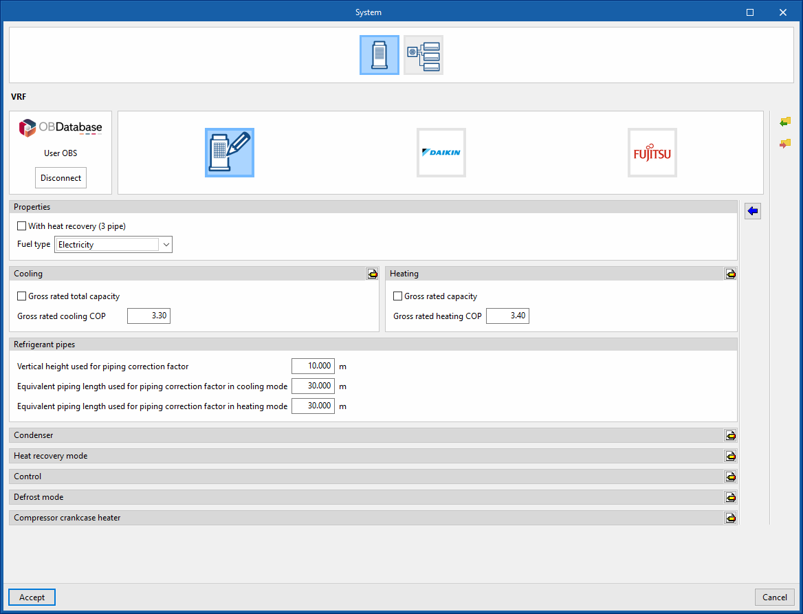
VRF
Generic
Characteristics
- With heat recovery (3 pipe) (optional)
- Fuel type (Electricity / Natural gas / LPG / Diesel / Coal / Biomass / Densified biomass (pellets))
Cooling
- Gross rated total capacity (optional)
Allows users to specify a value for the gross rated total capacity of the cooling unit. - Nominal cooling COP
- Advanced configuration
- Minimum outdoor temperature in cooling mode
- Maximum outdoor temperature in cooling mode
Heating
- Gross rated capacity (optional)
Allows users to specify a value for the gross rated capacity of the unit in heating mode. - Gross rated heating COP
- Advanced configuration
- Rated heating capacity sizing ratio
- Minimum outdoor temperature in heating mode
- Maximum outdoor temperature in heating mode
Refrigerant pipes
- Vertical height used for piping correction factor
- Equivalent piping length used for piping correction factor in cooling mode
- Equivalent piping length used for piping correction factor in heating mode
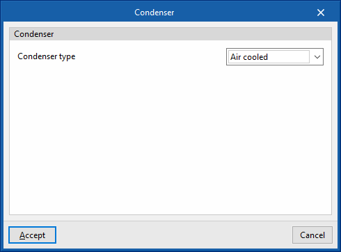
Condenser
- Condenser type (Air cooled / Water cooled / Evaporatively cooled)
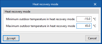
Heat recovery mode
- Minimum outdoor temperature in heat recovery mode
- Maximum outdoor temperature in heat recovery mode
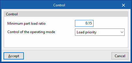
Control
- Minimum part load ratio
- Control of the operating mode (Load priority / Zone priority / Thermostat offset priority / Master thermostat priority)
- Zone name for master thermostat location
Defrost mode
- Defrost strategy (Resistive / Reverse cycle)
- Resistive defrost heater capacity
- Control (Timed / On demand)
- Heat pump defrost time period fraction
- Defrost mode maximum outdoor temperature
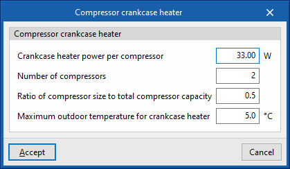
Compressor crankcase heater
- Crankcase heater power per compressor
- Number of compressors
- Ratio of compressor size to toal compressor capacity
- Maximum outdoor temperature for crankcase heater
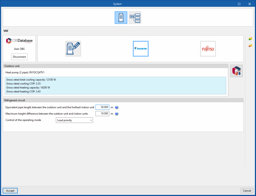
DManufacturer
Outdoor unit
- Open BIM Database unit selection
Allows users to select a variable refrigerant flow system outdoor unit from the manufacturers and models available in the Open BIM Database.
Refrigerant circuit
- Equivalent pipe length between the outdoor unit and furthest indoor unit
The length of the refrigerant pipes is used to correct the output of the VRF system, according to the manufacturer's instructions. - Maximum height difference between the outdoor unit and indoor units
The height difference between units is used to correct the power of the VRF system, according to the manufacturer's instructions. The height difference is indicated with a positive sign if the outdoor unit is installed above the indoor units and a negative sign if the outdoor unit is installed below the indoor units. - Control of the operating mode (Load priority / Zone priority / Thermostat offset priority / Master thermostat priority)
- Zone name for master thermostat location
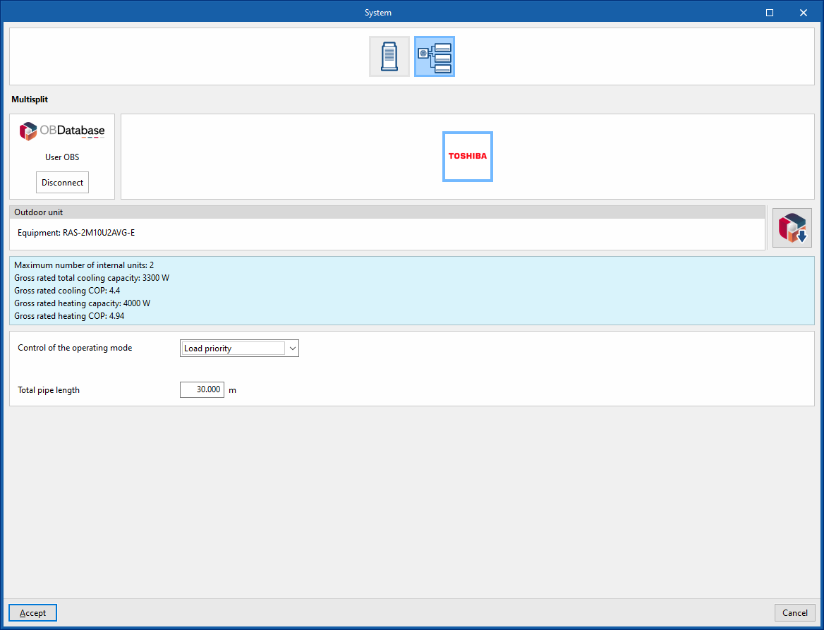
Multisplit
Manufacturer
Outdoor unit
- Open BIM Database unit selection
Allows users to select a variable refrigerant flow system outdoor unit from the manufacturers and models available in the Open BIM Database.
Refrigerant circuit
- Control of the operating mode (Load priority / Zone priority / Thermostat offset priority / Master thermostat priority)
- Zone name for master thermostat location
- Total pipe length
Air-air conditioning systems
Air-air conditioning systems include centralised ventilation systems and all-air systems with air-conditioning units. These systems are linked to air-conditioning terminal units defined in the zones.
Central ventilation systems are as follows:
- Heat recovery unit
- Dedicated outdoor air system (DOAS)
Air handling units are classified according to the number of supply ducts and the type of control:
- Air handling unit, constant air flow system
- Air handling unit, variable airflow system
- Air handling unit, constant flow all-air system with double duct
- Air handling unit, variable flow all-air system with double duct
Air-air conditioning systems. Central ventilation system
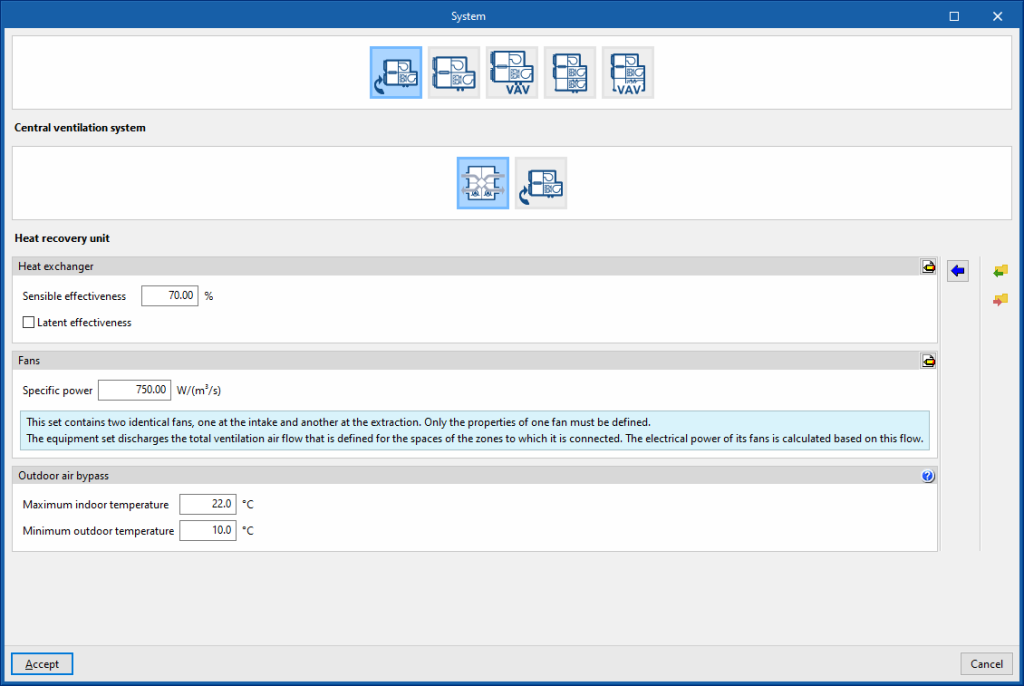
Heat recovery unit
Heat exchanger
- Sensible effectiveness
- Latent effectiveness (optional)
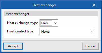
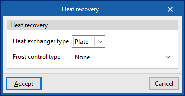
- Advanced configuration
- Heat exchanger type (Plate / Rotary)
- Frost control type (None / Exhaust air recirculation / Exhaust only / Minimum exhaust temperature)
Fans
- Specific power
- Advanced configuration
- Maximum air flow rate (optional)
- Motor efficiency
- Motor heat losses fraction in air stream
The unit drives the total ventilation airflow defined in the spaces of the zones to which it is connected. The electrical power of its fans is calculated according to this flow rate.
Outdoor air bypass
- Maximum indoor temperature
- Minimum outdoor temperature
- The indoor temperature is greater than the maximum indoor temperature.
- The outdoor temperature is greater than the minimum outdoor temperature.
- The outdoor temperature is less than the indoor temperature.

Dedicated outdoor air system (DOAS)
This air conditioner only treats primary air (ventilation air) and has no load control capability. In other words, it does not follow the zone thermostat and only tempers the outside air. It has two identical fans, supply and extract.
Cooling (optional)
- Cooling coil type (Single speed DX / Cold water)
Sets the characteristics of the cooling coil:- Single speed DX
- Gross rated sensible heat ratio
The gross rated sensible heat ratio is the ratio of the nominal sensible capacity to the gross rated capacity. - Gross rated capacity (optional)
- Nominal cooling COP
- Gross rated sensible heat ratio
- Cold water
- Chilled-water system
Allows users to select a chilled-water system defined in the "Air conditioning systems" section.
- Chilled-water system
- Single speed DX
- Advanced configuration
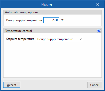
- Automatic sizing options
- Design supply temperature
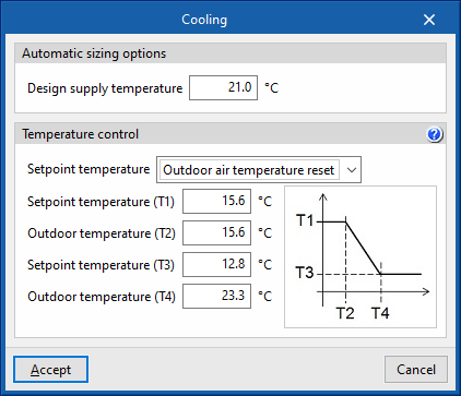
- Temperature control
- Setpoint temperature (Design supply temperature / Outdoor air temperature reset / Scheduled)
- Automatic sizing options
Heating (optional)
- Heating coil type (Single speed DX / Hot water / Gas / Electrical)
This sets the characteristics of the heating coil:- Single speed DX
- Gross rated capacity (optional)
- Gross rated heating COP
- Hot water
- Hot-water system
Allows users to select a water heating system defined in the "Air conditioning systems" section or to enter it directly.
- Hot-water system
- Gas
- Gross rated capacity (optional)
- Advanced configuration
- Gas heating coil efficiency
- Parasitic electric load
- Electrical
- Gross rated capacity (optional)
- Single speed DX
- Advanced configuration
- Automatic sizing options
- Design supply temperature
- Temperature control
- Setpoint temperature (Design supply temperature / Outdoor air temperature reset / Scheduled)
- Automatic sizing options
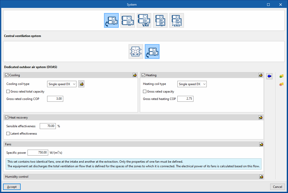
Heat recovery (optional)
- Sensible effectiveness
- Latent effectiveness (optional)
- Advanced configuration
- Heat exchanger type (Plate / Rotary)
- Frost control type (None / Exhaust air recirculation / Exhaust only / Minimum exhaust temperature)
Fans
- Specific power
- Advanced configuration
- Maximum air flow rate (optional)
- Motor efficiency
- Motor heat losses fraction in air stream
The equipment set discharges the total ventilation air flow that is defined for the spaces of the zones to which it is connected. The electrical power of its fans is calculated based on this flow.

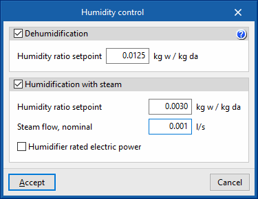
Humidity control
- Dehumidification (optional)
- Humidity ratio setpoint
- Humidity ratio setpoint (optional)
- Humidity ratio setpoint
- Steam flow, nominal
- Humidifier rated electric power (optional)
Air-air conditioning systems. Air handling unit, constant air flow system
In constant air flow systems, the air conditioner has a constant speed fan. The power supplied to the zones is adjusted by varying the temperature of the airflow to the zones. The fan will always be running.
Air handling unit, constant air flow system. “Air conditioning” tab
Cooling (optional)
- Cooling coil (Direct expansion / Cold water)
This sets the characteristics of the cooling coil:- Supply air flow
- Supply air flow (optional)
- Gross rated capacity (optional)
- Gross rated sensible heat ratio (optional)
The gross rated sensible heat ratio is the ratio of the nominal sensible capacity to the gross rated capacity. - Nominal cooling COP
- Cold water
- Chilled-water system
Allows users to select a chilled-water system defined in the "Air conditioning systems" section. - Supply air flow (optional)
- Advanced configuration
- Automatic sizing options
- Design supply temperature
- Automatic sizing options
- Chilled-water system
- Supply air flow
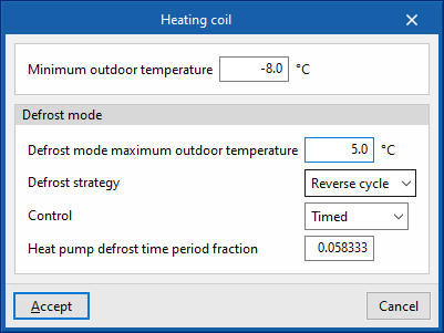
Heating (optional)
- Heating coil (Direct expansion / Electric / Gas / Hot water)
This sets the characteristics of the heating coil:- Direct expansion
- Supply air flow (optional)
- Gross rated capacity (optional)
- Gross rated heating COP
- Advanced configuration
- Minimum outdoor temperature
- Defrost mode
- Defrost mode maximum outdoor temperature
- Defrost strategy (Reverse cycle / Resistive)
- Control (Timed / On demand)
- Heat pump defrost time period fraction
- Electric
- Supply air flow (optional)
- Gross rated capacity (optional)
- Gas
- Supply air flow (optional)
- Gross rated capacity (optional)
- Advanced configuration
- Gas heating coil efficiency
- Parasitic electric load
- Hot water
- Hot-water system
Allows users to select a hot-water system defined in the "Air conditioning systems" section. - Supply air flow (optional)
- Hot-water system
- Advanced configuration
- Automatic sizing options
- Design supply temperature
- Automatic sizing options
- Direct expansion
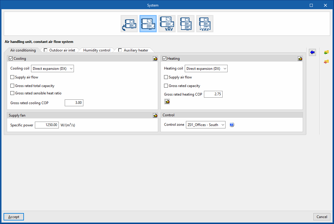


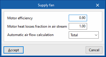
Supply fan
- Specific power
- Advanced configuration
- Motor efficiency
- Motor heat losses fraction in air stream
- Automatic air flow calculation (Simultaneous / Total)
Control
- Control zone
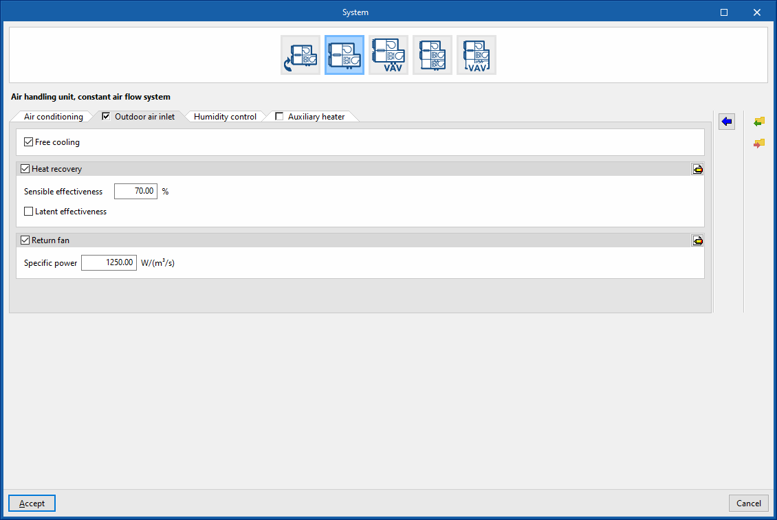
Air handling unit, constant air flow system. “Outdoor air inlet” tab (optional)
If the “Outdoor air inlet” tab is deactivated, the system only recirculates air from the heating zones.
Free cooling (optional)
Heat recovery (optional)
- Sensible effectiveness
- Latent effectiveness (optional)
- Advanced configuration
- Heat exchanger type (Plate / Rotary)
- Frost control type (None / Exhaust air recirculation / Exhaust only / Minimum exhaust temperature)
Supply fan (optional)
- Specific power
- Advanced configuration
- Motor efficiency
- Automatic air flow calculation (Simultaneous / Total)
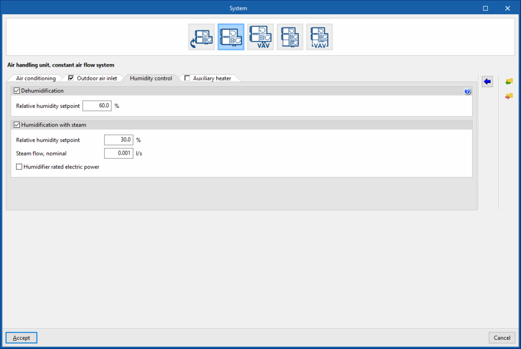
Air handling unit, constant air flow system. “Humidity control” tab
Dehumidification (optional)
The dehumidification of the air is carried out by its cooling and subsequent reheating. To do this, you must define a cold battery and an auxiliary heater.
- Relative humidity setpoint
Humidification with steam (optional)
- Relative humidity setpoint
- Steam flow, nominal
- Humidifier rated electric power (optional)
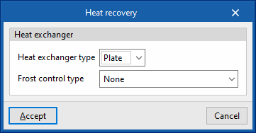
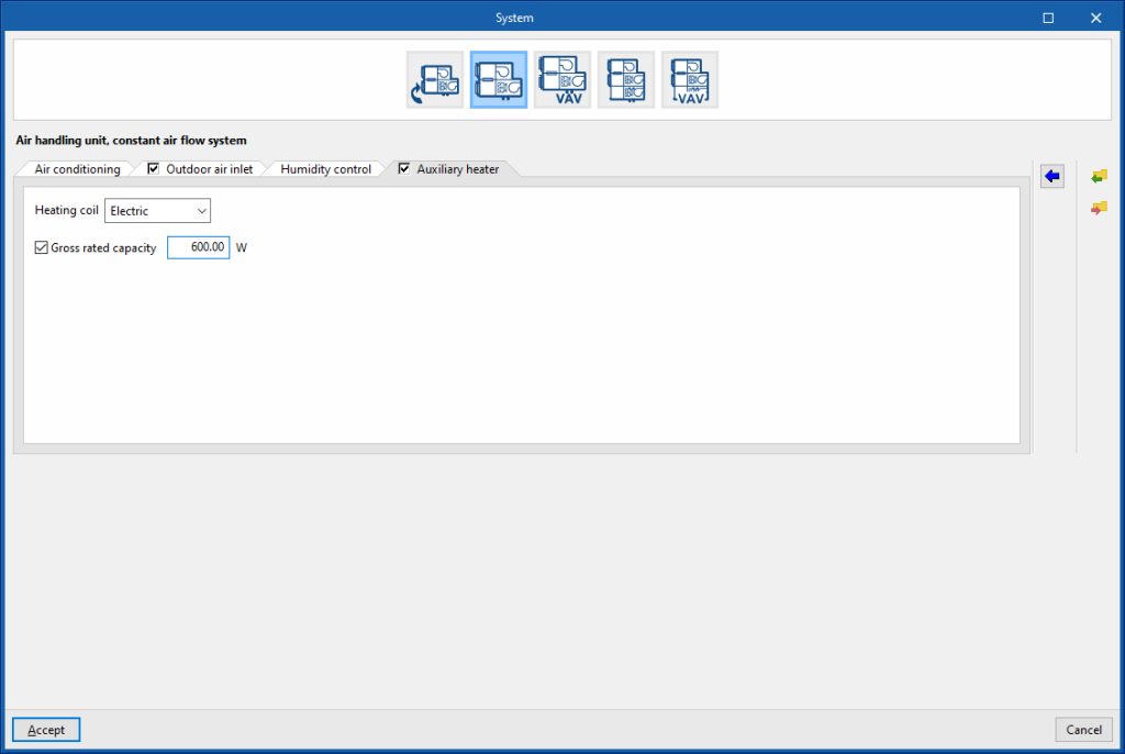
Air handling unit, constant air flow system. “Auxiliary heater” tab
- Heating coil (Electric / Gas / Desuperheater)
- Electric
- Gross rated capacity (optional)
- Gas
- Gross rated capacity (optional)
- Gas heating coil efficiency
- Parasitic electric load
- Desuperheater
- Electric
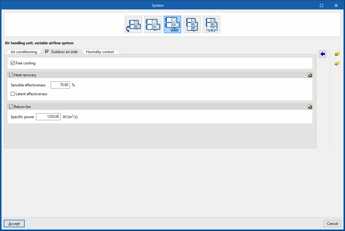
Air-air conditioning systems. Air handling unit, variable airflow system
In variable airflow systems, the air conditioner has a variable speed fan. The power delivered to the zones is adjusted at the terminal units (variable flow units) by varying the air flow rate. The supply temperature can be controlled in several ways. The fan will always be running.
EnergyPlus™ variable airflow systems are designed to operate with a terminal reheat for heating control.
Air handling unit, variable airflow system. “Air conditioning” tab
Cooling (optional)
- Cooling coil (Direct expansion / Cold water)
This sets the characteristics of the cooling coil:- Supply air flow
- Gross rated capacity (optional)
- Gross rated sensible heat ratio (optional)
The gross rated sensible heat ratio is the ratio of the nominal sensible capacity to the gross rated capacity. - Nominal cooling COP
- Cold water
- Chilled-water system
Allows users to select a chilled-water system defined in the "Air conditioning systems" section.
- Chilled-water system
- Advanced configuration
- Automatic sizing options
- Design supply temperature
- Temperature control (Maximum temperature / Minimum temperature)
- Maximum temperature
This option calculates the supply air temperature needed to overcome the cooling demand of the critical zone at the maximum supply flow rate. This temperature shall be as high as possible. Therefore, this strategy minimises the cooling generator consumption in exchange for higher fan consumption. - Minimum temperature
This option calculates the supply air temperature needed to overcome the cooling demand of the critical zone at the maximum supply flow rate. This temperature shall be as low as possible. Therefore, this strategy minimises the cooling generator consumption in exchange for higher fan consumption.- Minimum air flow fraction
The minimum air flow fraction must match the one defined in the terminal units connected to this unit.
- Minimum air flow fraction
- Maximum temperature
- Automatic sizing options
- Supply air flow
Heating (optional)
- Heating coil (Direct expansion / Electric / Gas / Hot water)
This sets the characteristics of the heating coil:- Direct expansion
- Gross rated capacity (optional)
- Gross rated heating COP
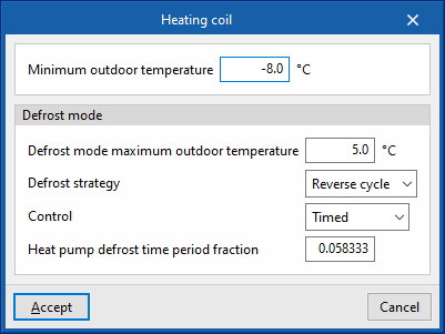
- Advanced configuration
- Minimum outdoor temperature
- Defrost mode
- Defrost mode maximum outdoor temperature
- Defrost strategy (Reverse cycle / Resistive)
- Control (Timed / On demand)
- Heat pump defrost time period fraction
- Electric
- Gross rated capacity (optional)
- Gas
- Gross rated capacity (optional)
- Advanced configuration
- Gas heating coil efficiency
- Parasitic electric load
- Hot water
- Hot-water system
Allows users to select a hot-water system defined in the "Air conditioning systems" section.
- Hot-water system
- Advanced configuration
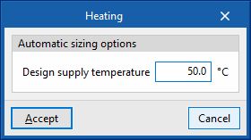
- Automatic sizing options
- Design supply temperature
- Automatic sizing options
- Direct expansion
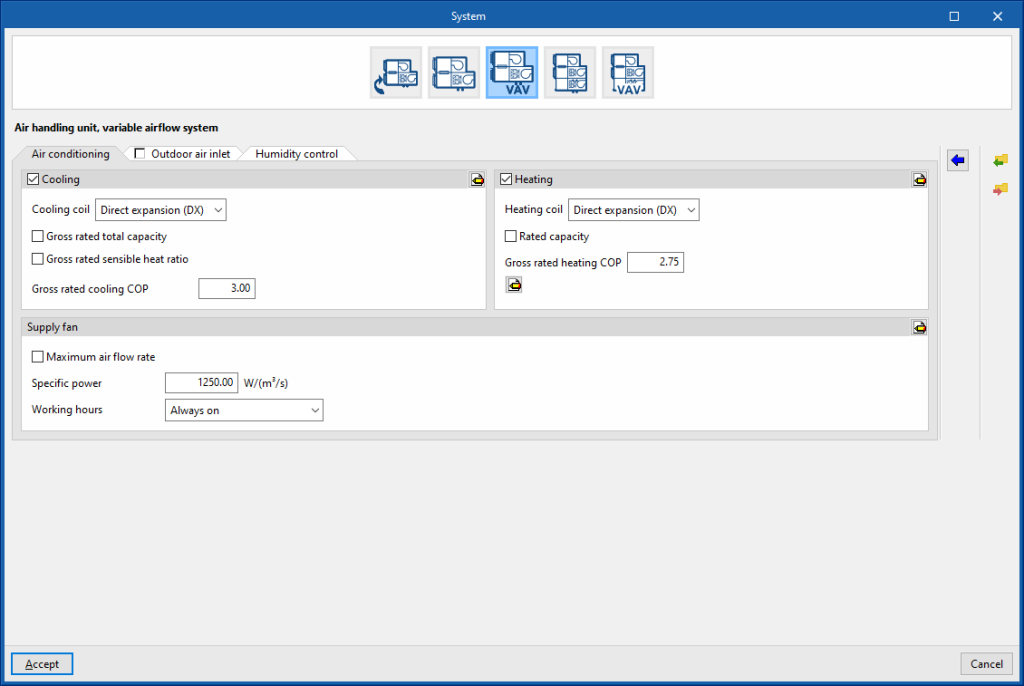

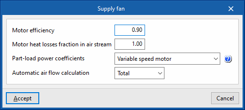
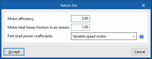
Supply fan
- Maximum air flow rate (optional)
- Specific power
- Working hours (Always on / Only with active ventilation)
- Advanced configuration
- Motor efficiency
- Motor heat losses fraction in air stream
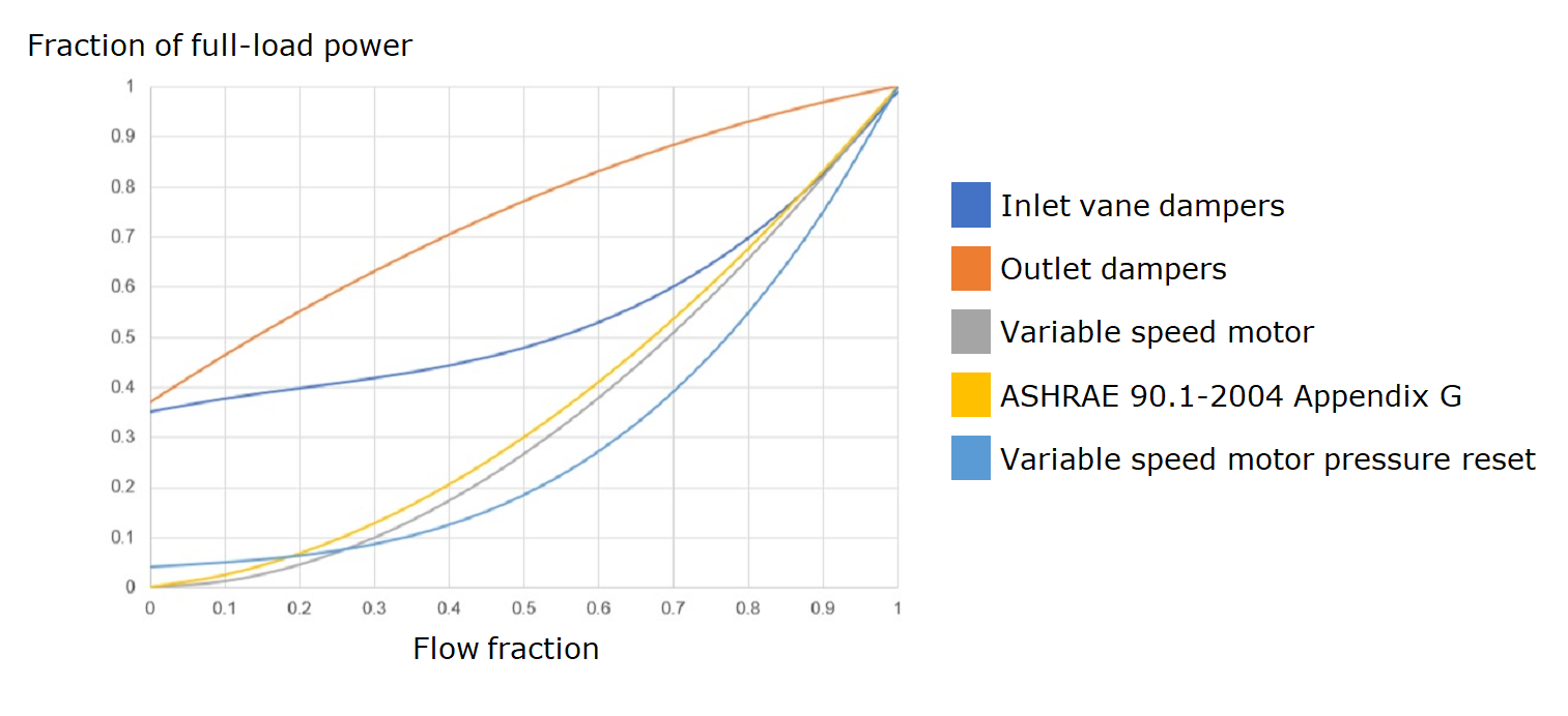
- Part-load power coefficients (Inlet vane dampers / Outlet dampers / Variable speed motor / ASHRAE 90.1-2004 Appendix G / Variable speed motor pressure reset)
- Automatic air flow calculation (Simultaneous / Total)
Air handling unit, variable airflow system. “Outdoor air inlet” tab
If the “Outdoor air inlet” tab is deactivated, the system only recirculates air from the heating zones.
Free cooling (optional)
Heat recovery (optional)
- Sensible effectiveness
- Latent effectiveness (optional)
- Advanced configuration
- Heat exchanger type (Plate / Rotary)
- Frost control type (None / Exhaust air recirculation / Exhaust only / Minimum exhaust temperature)
Supply fan (optional)
- Specific power
- Advanced configuration
- Motor efficiency
- Motor heat losses fraction in air stream
- Part-load power coefficients (Inlet vane dampers / Outlet dampers / Variable speed motor / ASHRAE 90.1-2004 Appendix G / Variable speed motor pressure reset)

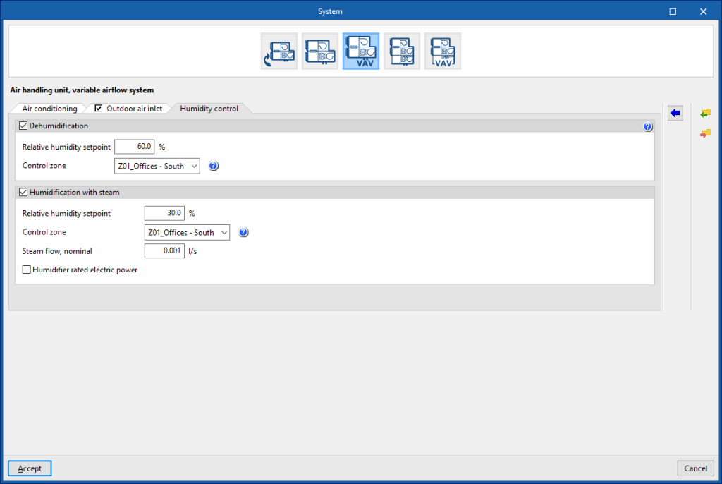
Air handling unit, variable airflow system. “Humidity control” tab
Dehumidification (optional)
The dehumidification of the air is carried out by its cooling and subsequent reheating.
- Relative humidity setpoint
- Control zone
The control zone is that which contains the thermostat associated with this equipment. A zone that contains a terminal unit connected to this equipment must be selected.
Humidification with steam (optional)
- Relative humidity setpoint
- Control zone
The control zone is that which contains the thermostat associated with this equipment. A zone that contains a terminal unit connected to this equipment must be selected. - Steam flow, nominal
- Humidifier rated electric power (optional)
Air-air conditioning systems. Air handling unit, constant flow all-air system with double duct
Dual-duct systems have two supply ducts, one for cold air and one for warm air. The terminal units are mixing boxes to which both ducts lead. For constant air flow systems, the fan is a fixed speed fan. Regulation is achieved by mixing air from both ducts in the terminal units (mixing boxes). The fans will always be running.
Air handling unit, constant flow all-air system with double duct. “Air conditioning” tab
Cooling (optional)
- Cooling coil (Cold water)
This sets the characteristics of the cooling coil:- Cold water
- Chilled-water system
Allows users to select a chilled-water system defined in the "Air conditioning systems" section.
- Chilled-water system
- Advanced configuration
- Automatic sizing options
- Design supply temperature
- Automatic sizing options
- Cold water
Heating (optional)
- Heating coil (Direct expansion / Electric / Gas)
Sets the characteristics of the heating coil:- Hot water
- Hot-water system
Allows users to select a hot-water system defined in the "Air conditioning systems" section.
- Hot-water system
- Electric
- Gross rated capacity (optional)
- Gas
- Gross rated capacity (optional)
- Advanced configuration
- Gas heating coil efficiency
- Parasitic electric load
- Advanced configuration
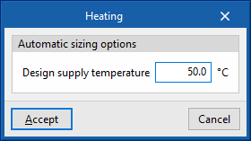
- Automatic sizing options
- Design supply temperature
- Automatic sizing options
- Hot water
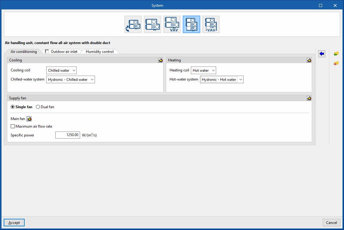

Supply fan
- Advanced configuration
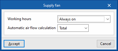
- Working hours (Always on / Only with active ventilation)
- Automatic air flow calculation (Simultaneous / Total)
- Single fan
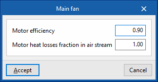
- Main fan
- Motor efficiency
- Motor heat losses fraction in air stream
- Maximum air flow rate (optional)
- Specific power
- Main fan
- Dual fan
- Cooling duct fan
- Motor efficiency
- Motor heat losses fraction in air stream
- Maximum air flow rate (optional)
- Specific power
- Heating duct fan
- Motor efficiency
- Motor heat losses fraction in air stream
- Maximum air flow rate (optional)
- Specific power
- Cooling duct fan


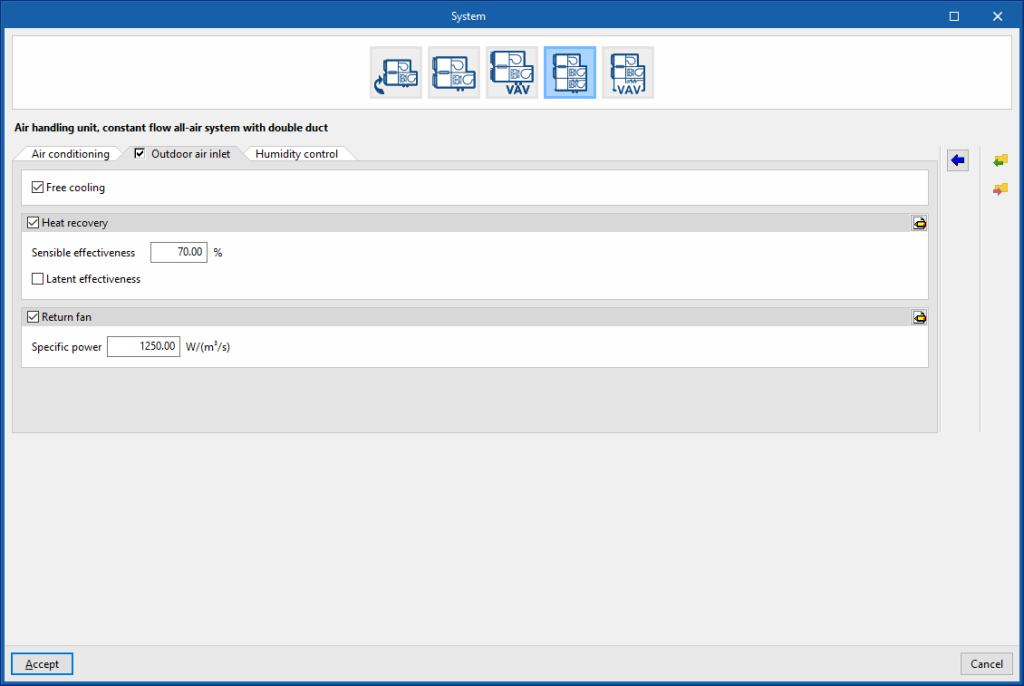
Air handling unit, constant flow all-air system with double duct. “Outdoor air inlet” tab (optional)
If the “Outdoor air inlet” tab is deactivated, the system only recirculates air from the heating zones.
Free cooling (optional)
Heat recovery (optional)
- Sensible effectiveness
- Latent effectiveness (optional)
- Advanced configuration
- Heat exchanger type (Plate / Rotary)
- Frost control type (None / Exhaust air recirculation / Exhaust only / Minimum exhaust temperature)
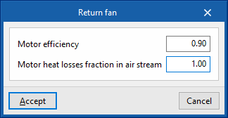
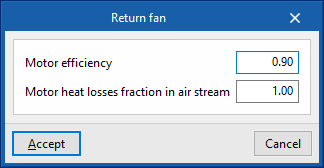
Return fan (optional)
- Specific power
- Advanced configuration
- Motor efficiency
- Motor heat losses fraction in air stream

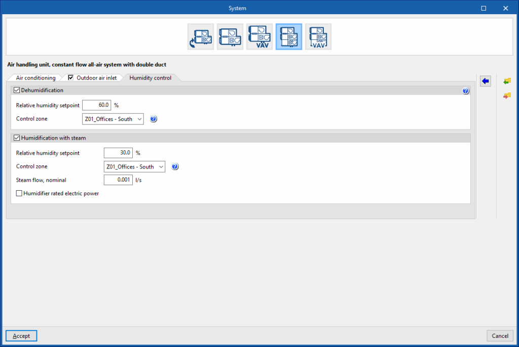
Air handling unit, constant flow all-air system with double duct. “Humidity control” tab
Dehumidification (optional)
The dehumidification of the air is carried out by its cooling and subsequent reheating.
- Relative humidity setpoint
- Control zone
The control zone is that which contains the thermostat associated with this equipment. A zone that contains a terminal unit connected to this equipment must be selected.
Humidification with steam (optional)
- Relative humidity setpoint
- Control zone
The control zone is that which contains the thermostat associated with this equipment. A zone that contains a terminal unit connected to this equipment must be selected. - Steam flow, nominal
- Humidifier rated electric power (optional)
Air-air conditioning systems. Air handling unit, variable flow all-air system with double duct
Dual-duct systems have two supply ducts, one for cold air and one for warm air. The terminal units are mixing boxes to which both ducts lead. In the case of variable airflow systems, the fan is variable speed. The terminal units are mixing boxes that also have dampers for varying the flow rate. The fans will always be running.
Air handling unit, variable flow all-air system with double duct. “Air conditioning” tab
Cooling (optional)
- Cooling coil (Cold water)
This sets the characteristics of the cooling coil:- Cold water
- Chilled-water system
Allows users to select a chilled-water system defined in the "Air conditioning systems" section.
- Chilled-water system
- Advanced configuration
- Automatic sizing options
- Design supply temperature
- Temperature control
- Maximum temperature
This option calculates the supply air temperature needed to overcome the cooling demand of the critical zone at the maximum supply flow rate. This temperature shall be as high as possible. Therefore, this strategy minimises the cooling generator consumption in exchange for higher fan consumption. - Minimum temperature
This option calculates the supply air temperature needed to overcome the cooling demand of the critical zone at the maximum supply flow rate. This temperature shall be as low as possible. Therefore, this strategy minimises the cooling generator consumption in exchange for higher fan consumption.- Minimum air flow fraction
The minimum air flow fraction must match the one defined in the terminal units connected to this unit.
- Minimum air flow fraction
- Maximum temperature
- Automatic sizing options
- Cold water
Heating (optional)
- Heating coil (Direct expansion / Electric / Gas)
This sets the characteristics of the heating coil:- Hot water
- Hot-water system
Allows users to select a hot-water system defined in the "Air conditioning systems" section.
- Hot-water system
- Electric
- Gross rated capacity (optional)
- Gas
- Gross rated capacity (optional)
- Advanced configuration
- Gas heating coil efficiency
- Parasitic electric load
- Advanced configuration
- Automatic sizing options
- Design supply temperature
- Automatic sizing options
- Hot water
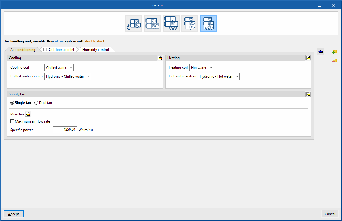
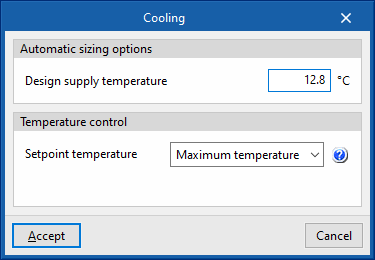

Supply fan
- Advanced configuration
- Horario de funcionamiento (Siempre encendido / Sólo con la Working hours (Always on / Only with active ventilation)
- Automatic air flow calculation (Simultaneous / Total)

- Simple fan
- Main fan
- Motor efficiency
- Motor heat losses fraction in air stream
- Maximum air flow rate (optional)
- Specific power
- Main fan
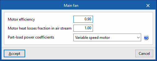
- Dual fan
- Cooling duct fan
- Motor efficiency
- Motor heat losses fraction in air stream
- Maximum air flow rate (optional)
- Specific power
- Heating duct fan
- Motor efficiency
- Motor heat losses fraction in air stream
- Maximum air flow rate (optional)
- Specific power
- Cooling duct fan

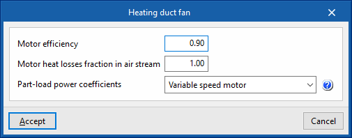
Air handling unit, variable flow all-air system with double duct. “Outdoor air inlet” tab (optional)
If the “Outdoor air inlet” tab is deactivated, the system only recirculates air from the heating zones.
Free cooling (optional)
Heat recovery (optional)
- Sensible effectiveness
- Latent effectiveness (optional)
- Advanced configuration
- Heat exchanger type (Plate / Rotary)
- Frost control type (None / Exhaust air recirculation / Exhaust only / Minimum exhaust temperature)
Return fan (optional)
- Specific power
- Advanced configuration
- Motor efficiency
- Motor heat losses fraction in air stream
- Part-load power coefficients (Inlet vane dampers / Outlet dampers / Variable speed motor / ASHRAE 90.1-2004 Appendix G / Variable speed motor pressure reset)
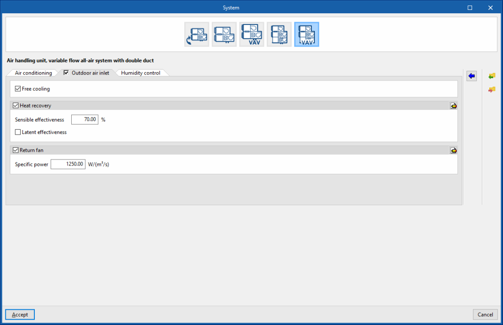


Air handling unit, variable flow all-air system with double duct. “Humidity control” tab
Dehumidification (optional)
The dehumidification of the air is carried out by its cooling and subsequent reheating.
- Relative humidity setpoint
- Control zone
The control zone is that which contains the thermostat associated with this equipment. A zone that contains a terminal unit connected to this equipment must be selected.
Humidification with steam (optional)
- Relative humidity setpoint
- Control zone
The control zone is that which contains the thermostat associated with this equipment. A zone that contains a terminal unit connected to this equipment must be selected. - Steam flow, nominal
- Humidifier rated electric power (optional)
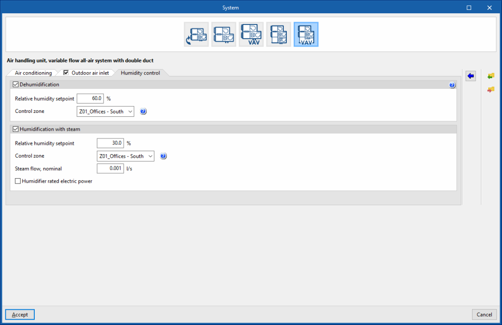
Water-cooled system
Water-cooled systems include condensing systems for reversible heat pumps, using cooling towers and boilers, condensing systems for chillers, using single or two-speed cooling towers, and water-cooled systems at a defined, constant or time-controlled temperature.
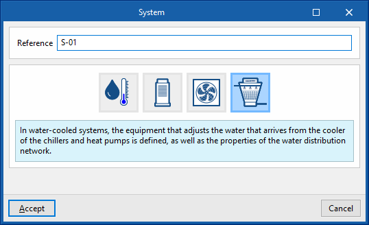
Water-cooled system for reversible heat pump
Equipment
Boiler
- Reference
Reference of the unit. - Heating
- Gross rated capacity (optional)
- Sizing factor
- Rated efficiency
If the performance curve is not defined, the efficiency value of the boiler measured at the following nominal conditions must be given:- Conventional boiler: water outlet at 82°C / Condensing boiler: water inlet at 70°C.
- Fuel type (Electricity / Natural gas / LPG / Diesel / Coal / Biomass / Densified biomass (pellets))
- Gross rated capacity (optional)
- Design parameters
- Water outlet upper temperature limit
- Minimum part load ratio
- Maximum part load ratio
- Optimum part load ratio
- Performance curves
- Default
- Conventional boiler / Condensing boiler
- User-defined
- Default
Cooling tower
- Reference
Reference of the unit. - Cooling tower
- Tower type (Single speed / Two speed)
- Free convection capacity
- Sizing factor
- Consumption
- In single-speed cooling towers:
- High speed nominal power (optional)
- High speed fan power (optional)
- In two-speed cooling towers:
- High speed nominal power (optional)
- High speed fan power (optional)
- Low speed nominal power (optional)
- Low speed fan power (optional)
- In single-speed cooling towers:
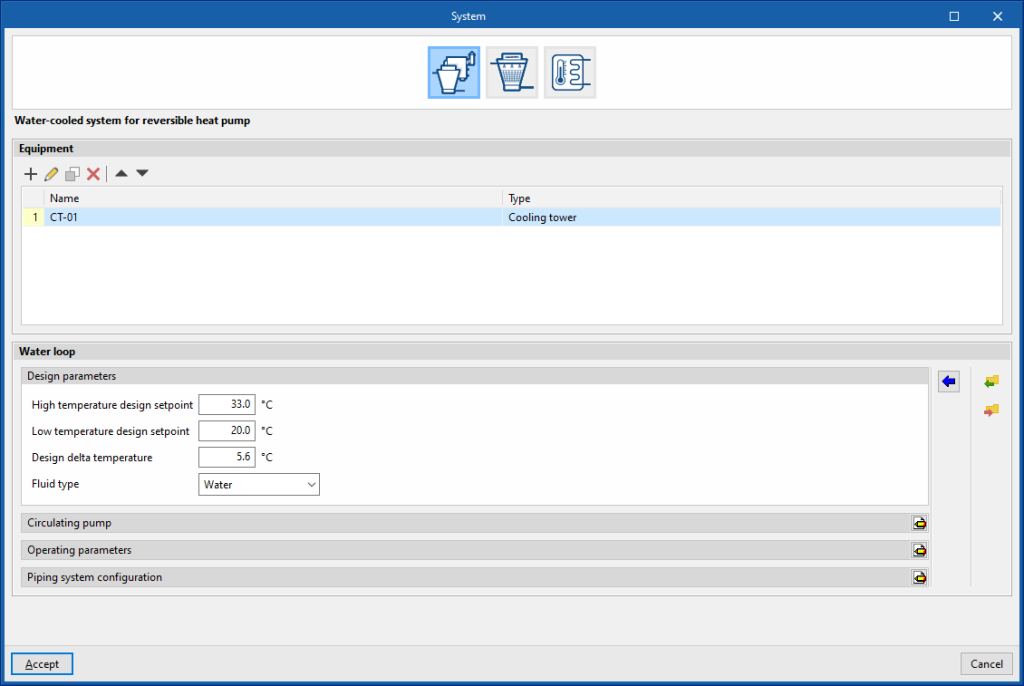
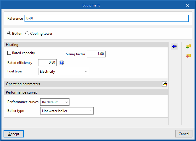
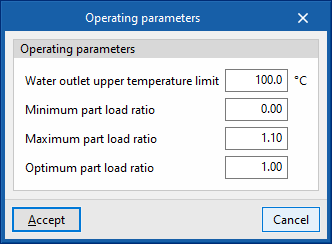
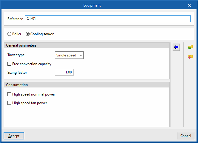
Water distribution
- Design parameters
- High temperature design setpoint
- Low temperature design setpoint
- Design delta temperature
- Type of fluid (Water / Ethylene glycol / Propylene glycol)
- Circulating pump
- Configuration (Variable flow / Constant flow)
- Control (Intermittent / Continuous)
- Primary loop pump type (Single pump / Pump per chiller / Two headered pumps / Three headered pumps / Four headered pumps / Five headered pumps)
- Primary loop pump rated head
- Primary loop pump rated head
- Load distribution scheme (Optimal / Sequential load / Uniform load / Uniform PLR / Sequential uniform PLR)
- Piping system configuration
- Supply side bypass pipe (optional)
- Demand side bypass pipe (optional)
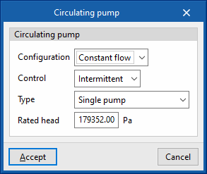
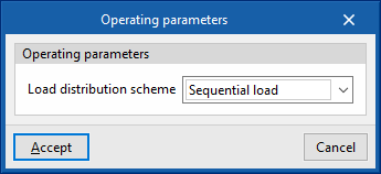

Water-cooled systems for chiller
Equipment
Cooling tower
- Reference
- General parameters
- Tower type (Single speed / Two speed)
- Free convection capacity
- Sizing factor
- Consumo
- In single-speed cooling towers:
- High speed nominal power (optional)
- High speed fan power (optional)
- In two speed cooling towers:
- High speed nominal power (optional)
- High speed fan power (optional)
- Low speed nominal power (optional)
- Low speed fan power (optional)
- In single-speed cooling towers:
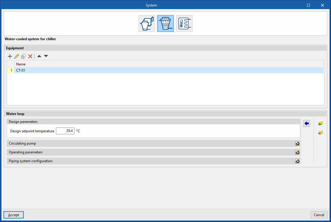
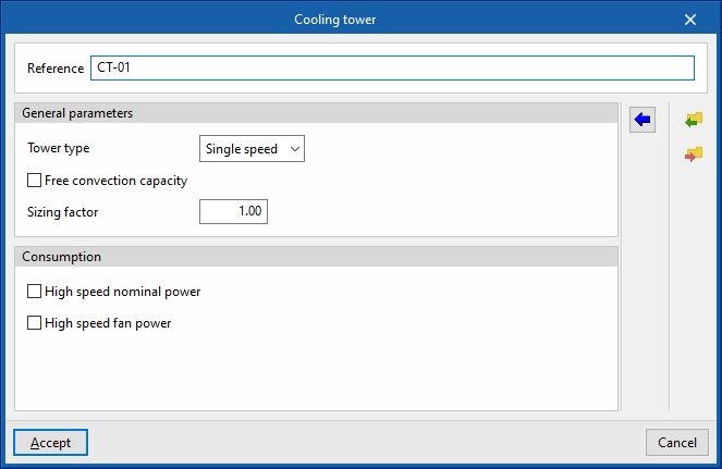
Water distribution
- Design parameters
- Design setpoint temperature
- Circulating pump
- Setpoint temperature control (Depending on the outdoor air wet bulb temperature / Design setpoint temperatur)
- Load distribution scheme (Optimal / Sequential load / Uniform load / Uniform PLR / Sequential uniform PLR)
- Operating parameters
- Setpoint temperature control (Depending on the outdoor air wet bulb temperature / Design setpoint temperatur)
- Load distribution scheme (Optimal / Sequential load / Uniform load / Uniform PLR / Sequential uniform PLR)
- Piping system configuration
- Supply side bypass pipe (optional)
- Demand side bypass pipe (optional)
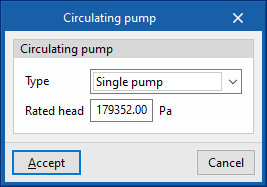
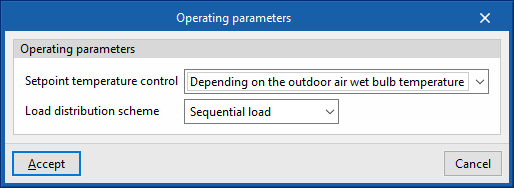

Water condensation systems at a defined temperature
This type of system allows users to simulate any water or glycol circuit connected to the external exchangers of the air-conditioning units. For example, it can be used to simulate a field of geothermal collectors or a groundwater flow. To do this, users simply need to define the temperature of the fluid at the outlet of the circuit and the characteristics of the circulation pump.
This condensing system is compatible with VRF chillers and outdoor units with water-cooled condensers as well as with the water-air heat pump.
Heat transfer fluid
- Temperature (Constant / Hourly profile
- Fluid type (Water / Ethylene glycol / Propylene glycol)
If an hourly profile is defined, users can distinguish between summer and winter conditions, and subtract or add a few degrees to the ground temperature to obtain the temperature of the heat transfer fluid.
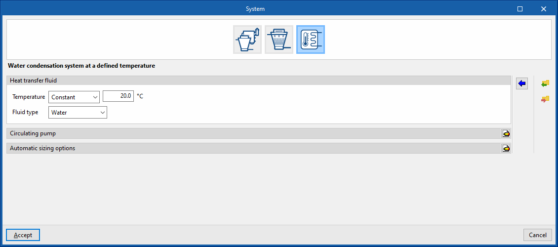
Circulating pump
- Control (Intermittent / Continuous)
- Configuration (Variable flow / Constant flow)
- Primary loop pump type (Single pump / Pump per chiller / Two headered pumps / Three headered pumps / Four headered pumps / Five headered pumps)
- Rated head

Automatic sizing options
The flow rate of the condensing circuit is equal to the sum of the flow rates defined in the condenser of the units connected to the circuit. If these flow rates have not been defined, the analysis engine will automatically size them, using the design temperature and design temperature difference values.
- Design temperature
- Design temperature difference