

Footings
Using the "Footings" module, CYPECAD and CYPE 3D can design foundations made of reinforced concrete rigid footings or mass concrete footings, either isolated or combined, with several freely configurable columns and shear walls. This module also designs tie and strap beams between footings and, additionally, in the case of CYPECAD, it also designs strip footings for walls.
General features of the Footings module
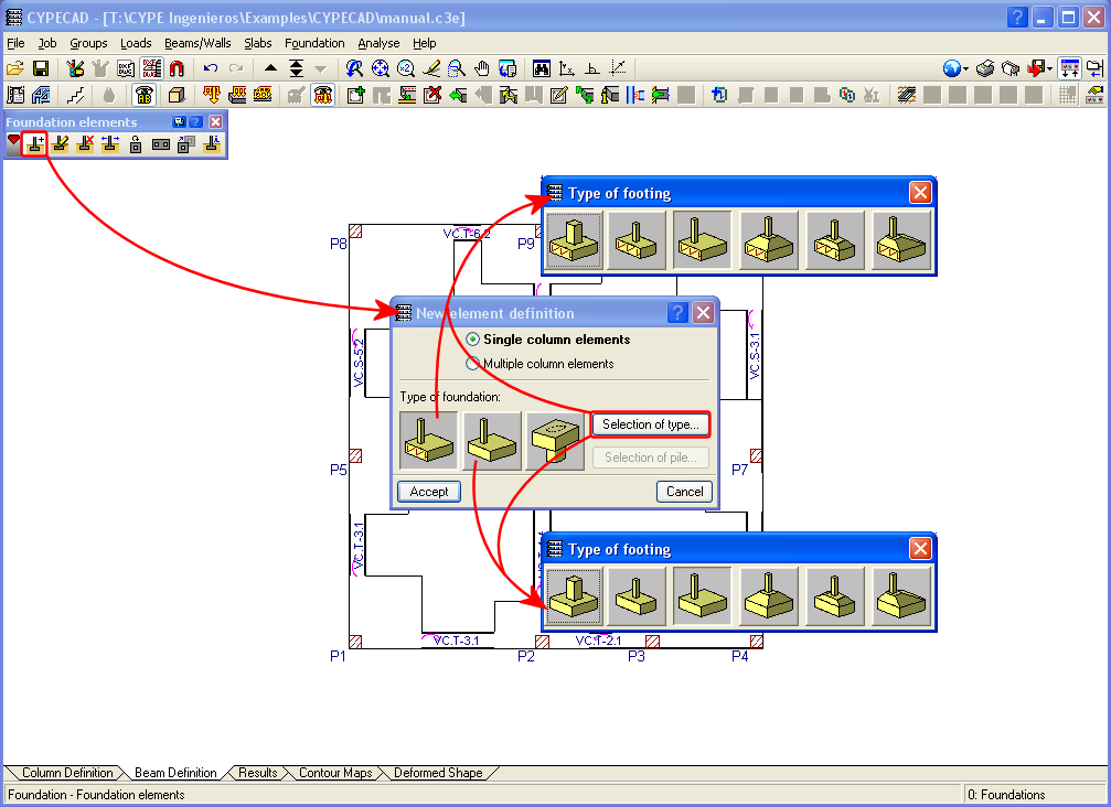
The tools required to introduce foundations with footings can be found as follows:
- CYPECAD
Foundation menu in the Beam Definition or Results tabs - CYPE 3D
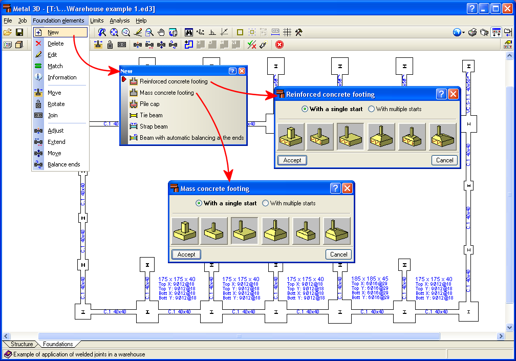
Foundation elements menu in the Foundation tab
In both programs, the Footings module can design (reinforced or mass concrete) footings with constant or variable depth (tapered) and obtain square, centred rectangular and eccentric rectangular footings (depending on the user's selection and the acting forces).
In CYPECAD and CYPE 3D it is possible to select several columns and shear walls to assign them a common footing.
As well as the Footings module, another module that complements this one by offering greater features in footing design is the Advanced calculation of surface foundations module, which allows CYPECAD and CYPE 3D to design foundations with footings that include trims in their geometry and CYPECAD to design foundations with tie and strap beams intersections.
Automatically generating footings, tie beams and strap beams
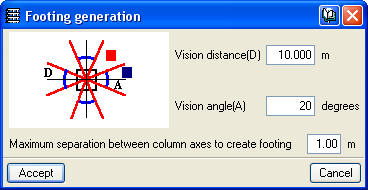
In CYPECAD, the Footings module allows the required strap beams and footings to be automatically introduced with a set of initial dimensions before starting the design process. The program determines corner or edge footings and automatically provides the strap beams required to centre the load of the eccentric footings. For this process, users must simply indicate the vision angle and vision distance for the program to detect the column layout of the structure.
The automatic generation of strap beams and footing may be very useful in those structures containing a large number of columns, as there is no need to introduce footings and strap beams one by one. Any of the foundation elements that are considered to have been inadequately generated can be modified later.
In CYPE 3D, the automatic footing generation is different. Here, the program generates all the centred footings and arranges tie beams between the columns forming the outline, as this is the most common situation in foundations for industrial warehouses. As in CYPECAD, the types of footing for each column can be manually selected by the user.
Strip footing for a wall
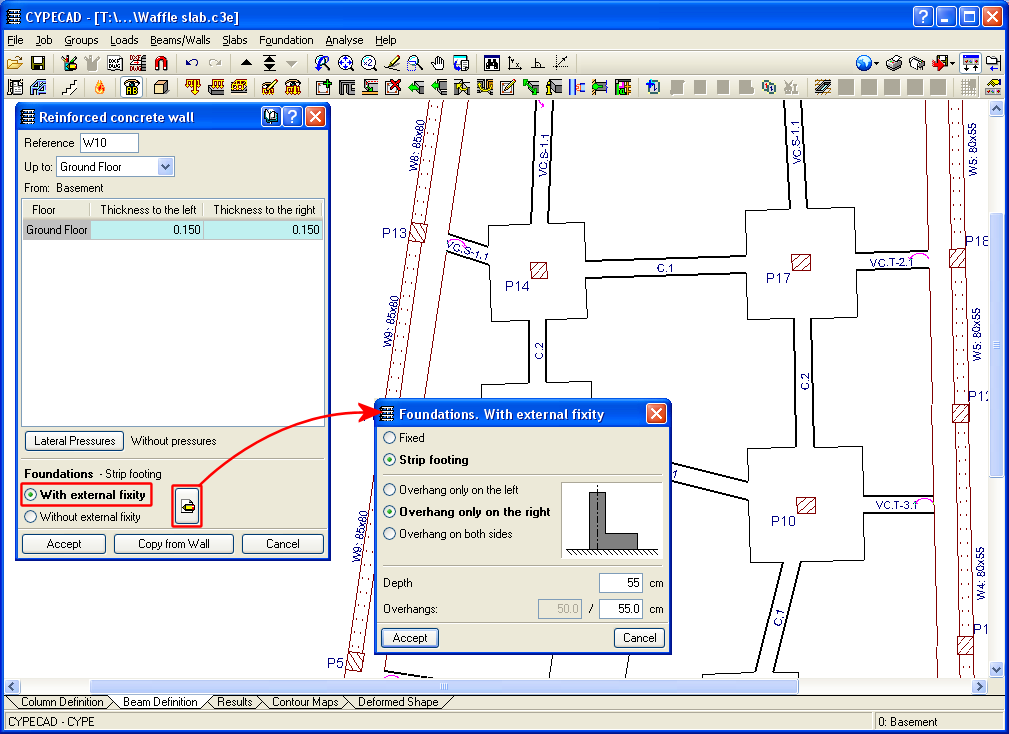
The foundations of the walls designed by CYPECAD can be With external fixity (strip footing below the wall) or Without external fixity (foundation beam). If the foundation of the wall is defined as a strip footing (with external fixity), the Footings module designs the footing from a set of minimum dimensions, as it does with column footings. If the wall footing is eccentric (with toe and without heel, for example) the strap beams joining it to the interior columns will be designed to balance the load of the footing.
Footing edition
After analysing and designing the structure and its foundation, users can edit any footing to visualise its design and reinforcement.
The footing editor also allows the users to change the type of footing, modify its dimensions and reinforcement, and even change the growth options during the design of the footing. Once the user has entered specifications, the editor can either check the footing with the changes introduced or design it. The design has three options:
- Complete
The footing is designed considering the changes carried out by the user in terms of the type of footing, materials and growth options. Any design or reinforcement changes that have been introduced will not be considered. - Minimum dimensions
The program checks the footings with the dimensions entered by users, considering any changes in materials that may have been introduced. If necessary, it increases the dimensions of the footing in accordance with the selected typology and the design options entered. The reinforcement can also be designed. - Redesign
The program redesigns and checks footing without modifying its dimensions.

Footing analysis and design
In the 2011 version, changes were made to the analysis of forces for foundations "with external fixity", both for footings and pile caps as well as for their tie beams and strap beams.
The current analysis may differ from previous versions. Now, after obtaining the reactions at the supports of the supporting elements of the structure (columns, shear walls and walls), a model is created with all the foundation elements "with external fixity" and their beams, represented by their stiffness matrix. The stiffness matrix, together with the loadcases defined as loads on the foundation (reactions obtained), is developed and completed by frontal methods to obtain the displacements and forces in all the elements so that the stiffnesses of all the elements intervene and interact with each other.
Iterations in the design process
First iteration
The design process is iterative and starts from the initial dimensions of each element. During the first iteration, the following considerations are established to determine the stiffness and fixity of each type of element:
- Pad footing or pile cap
It is considered as a rigid solid with a support in the centre, whose connection in each direction can be a pinned support if it supports a strap beam, or fixed if it supports a tie beam or no beam at all. - Strip footing for a wall
It is defined as a rigid solid with a support at its centre which, in the transverse direction, is considered pinned if it is supported by strap beams and/or other walls, and, in the longitudinal direction, it is considered fixed. - Tie beam
It is considered as a bar with its dimensions and pinned ends reaching the axis passing through the centre of the braced element. - Strap beam
It is considered as a bar with its dimensions. Its ends are fixed at the edge of the element it centres in the following cases:- Edge, corner footings, and one and two-pile caps, in the directions that need to be centred.
- When the user marks the balancing manually.
The ends of the strap beams are pinned in the following cases:
- Centred footing or three or more pile caps.
- Edge, corner footings, and one and two-pile caps, in the directions that don't need to be centred.
- When the user marks the centring manually. Therefore, the fixity of the ends can be modified by the user and, as with the tie beams, the ends reach the axis passing through the centre of the element to which it is linked.
- Perimeter walls and strap beams reaching transversely a strip footing
This combination of elements is a special case, although common in building construction. It can be seen in the following image.
- Given the great stiffness of the transverse perimeter walls (4) and (5), their effect would be massive compared to beams (1), (2) and (3), therefore, it has been simplified in such a way that the centring effect is distributed equally among all the elements that are transversely engaged, by averaging the stiffnesses of the strap beams and assigning this average stiffness to all the centring elements, including walls, so that they all contribute in a balanced and equal way.
For a precise analysis, soil-structure interaction and an appropriate model of the soil should be considered, however, given the complexity of this analysis, the aforementioned simplification is reasonable, since the footing is considered to be rigid and not subject to torsion..
Remaining iterations
The program carries out more or fewer iterations depending on the option chosen by the user:
- Quick design
Once the first iteration has been carried out, the footings and pile caps are designed with the stresses obtained, a second analysis iteration is carried out and the elements, including the beams, are designed again. With this last geometry, a third and final analysis is carried out and all the elements are checked, though there may still be some elements that do not comply. - Complete design
Once the first iteration has been carried out, the iterations would continue until every element is compliant, unless the maximum design limits allowed for each element are reached, in which case some elements would not be compliant.
CYPECAD versions
CYPECAD is available in its unlimited version and also in two limited versions called LT30 and LT50, which contain the same tools and module acquisition possibilities, but have the following conditions:
CYPECAD LT50:
- Fifty columns.
- Four floor groups (Floor group: floors which are the same and consecutive).
- Total of five floors.
- Walls: one hundred linear metres. Feature available with the Building walls module.
CYPECAD LT30:
- Thirty columns.
- Four floor groups (Floor group: floors which are the same and consecutive).
- Total of five floors.
- Walls: one hundred linear metres. Feature available with the Building walls module.
Integrated 3D structures of CYPECAD (also LT50 and LT30) is not technically a module. To define these 3D structures in CYPECAD, users must also have the required permits to use CYPE 3D in their user license and, optionally, modules that are exclusive to CYPE 3D.
Other features
In order to access further features offered by the program, there are several modules that can be found on the “CYPECAD modules” and “CYPE 3D modules” webpages.