Introduction
StruBIM Rebar is a tool for the reinforcement detailing of reinforced concrete structures, and can import the results and geometry of structural elements from other design tools in order to automatically generate a detailed 3D model of the reinforcement. As a result, the program exports the detailed three-dimensional reinforcement model in IFC and BVBS format, lists of material quantities and detailing drawings.
Workflows supported by the program
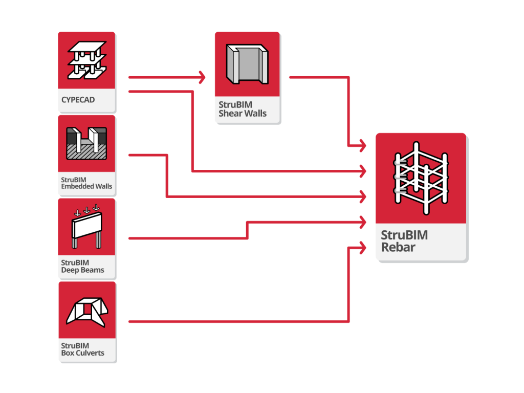
Via the Open BIM workflow proposed by the BIMserver.center platform users can do the following:
- design a reinforced concrete structure in CYPECAD;
- design shear walls in StruBIM Shear Walls;
- design embedded retaining walls and other retaining elements in StruBIM Embedded Walls;
- design deep beams in StruBIM Deep Beams.
- design underpasses for roads and civil works in StruBIM Box Culverts
The results obtained from these programs can then be exported to StruBIM Rebar, which allows users to check and adjust the detailed model of the reinforcement if required.
Work environment
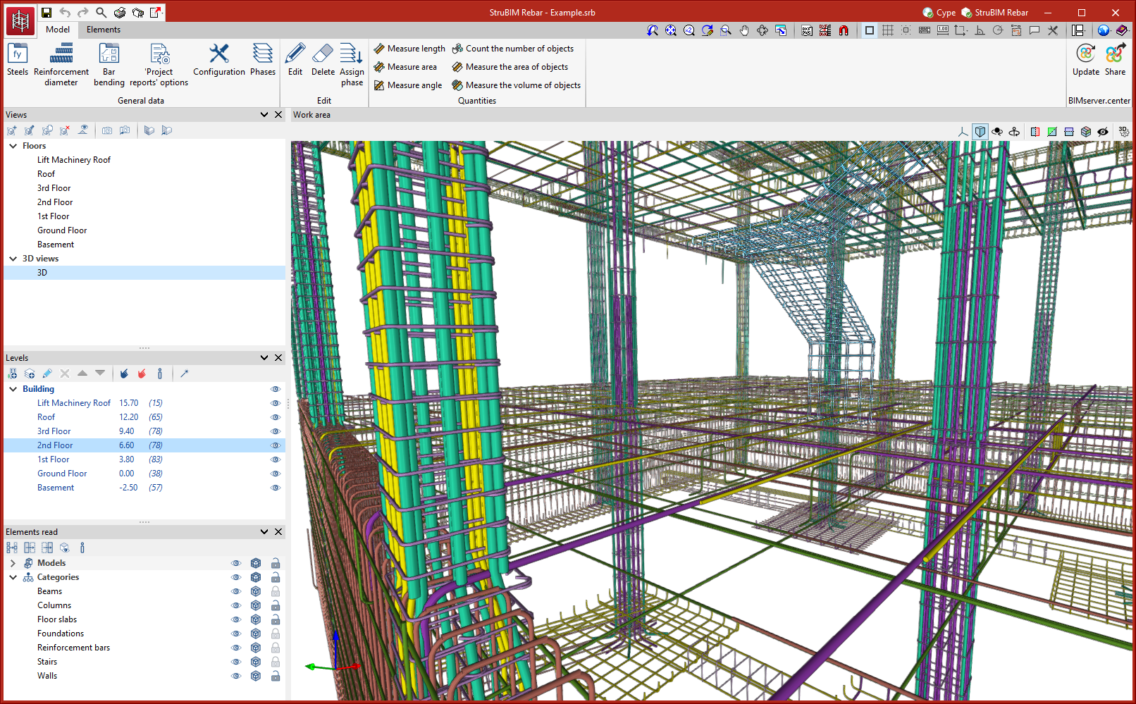
StruBIM Rebar's work environment is similar to other CYPE tools and features a system of dockable windows that can be customised to tailor the workspace to the project’s needs.
There are two separate tabs at the top left of the screen: "Model" and "Elements".
The main toolbar contains different features depending on which tab is selected. General data and project data can be defined here, and the editing tools, measurement tools and detailing check are located here.
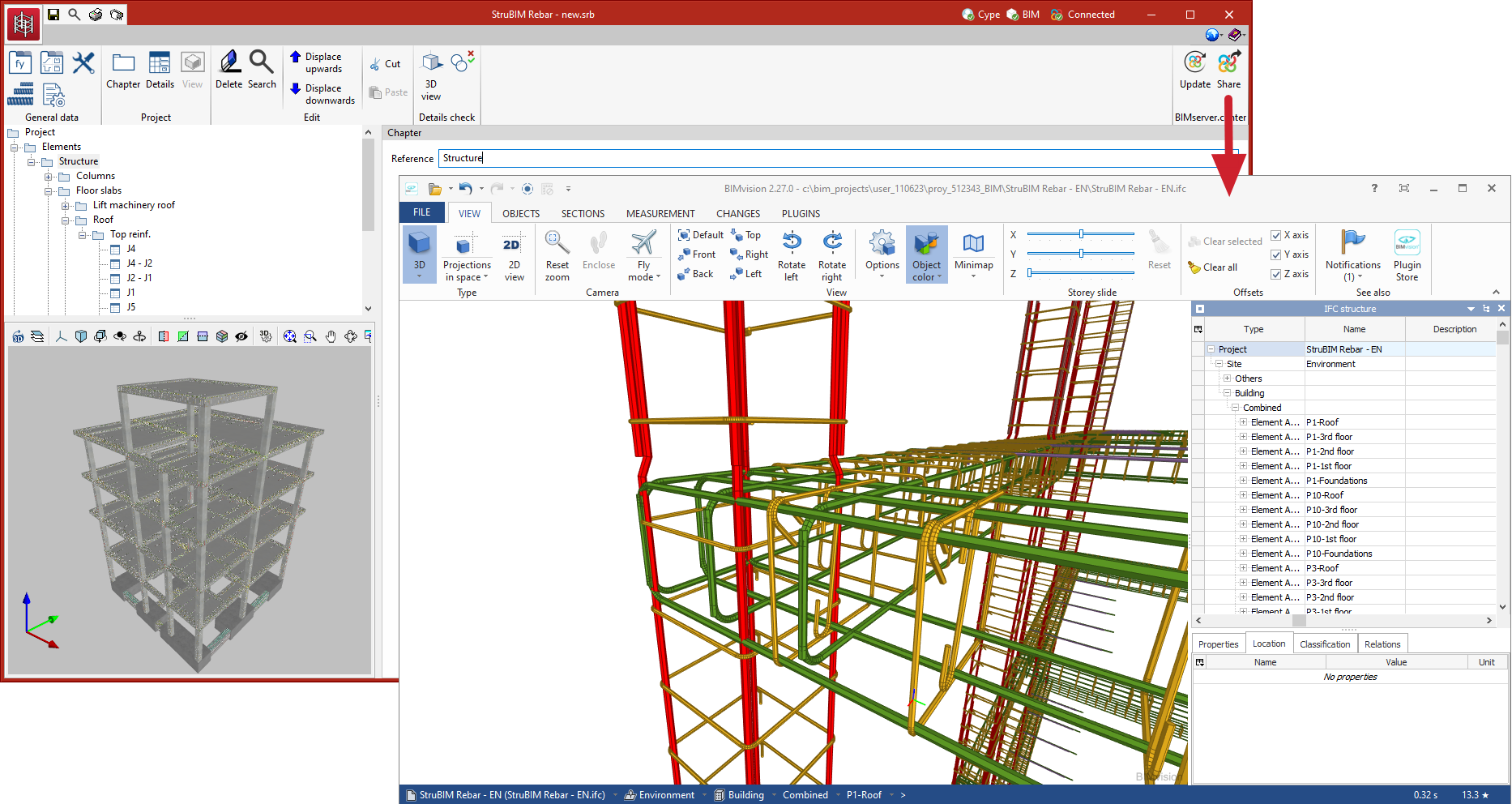
The "Model" tab contains the work area, in the central part, and a sidebar from which the views, levels and elements read from the BIM model can be managed.
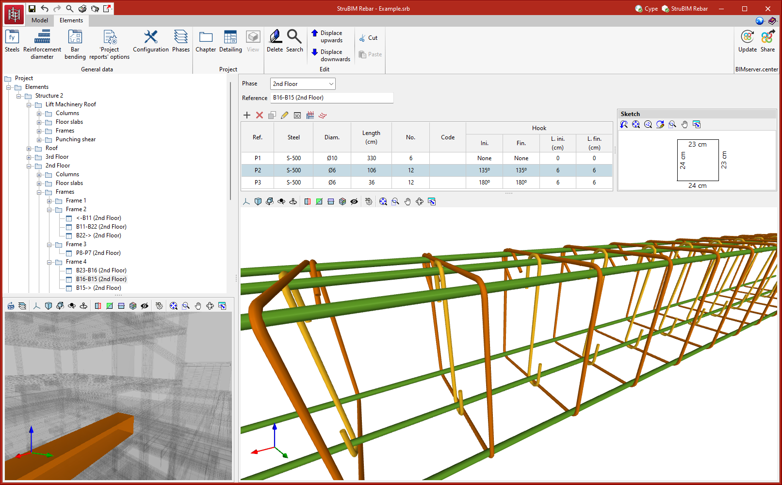
In the "Elements" tab, the elements of the imported structure are organised by means of a tree of work sections on the left. These elements are distributed according to their type (columns, beams, foundations, etc.) and the level at which they are located.
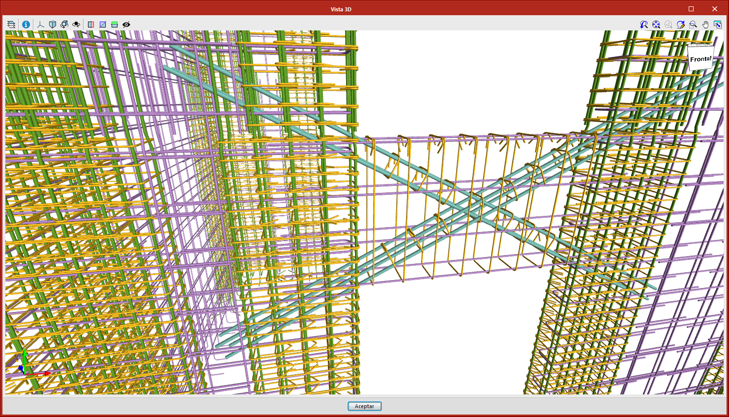
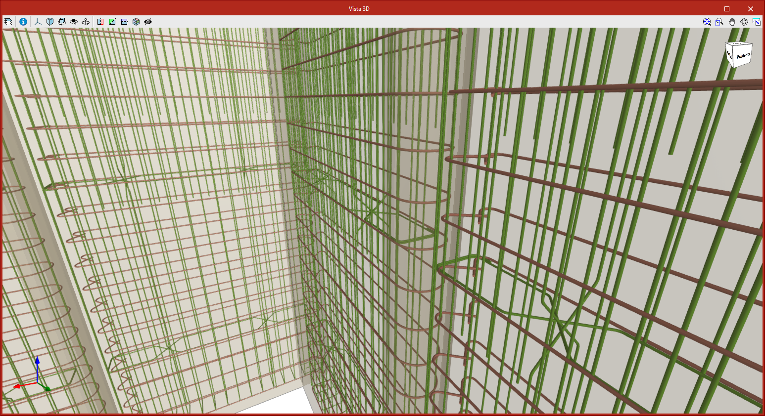
Each selected element is shown on the right-hand side. On the one hand, the 3D view of the detailing is shown (at the bottom) and on the other hand, the list of bar groups. Each detailing is therefore made up of one or more groups of bars. A group of bars is a set of identical bars (same diameter, shape and dimensions).
The detailing can be generated automatically during the import, set by the user or defined manually from scratch.
Toolbar
The toolbar is located at the top of the screen. It has several features organised in different sections, which vary depending on the tab selected, either "Model" or "Elements".
General data
In both the "Model" tab and the "Elements" tab, in the "General data" group of the main toolbar, the following project data can be defined:

Steels
This library contains the steel types used to define the reinforcement. For each type, users must define the reference, the yield strength and the material's modulus of elasticity. When importing data from other design programs, the imported steels will be automatically included in this table.
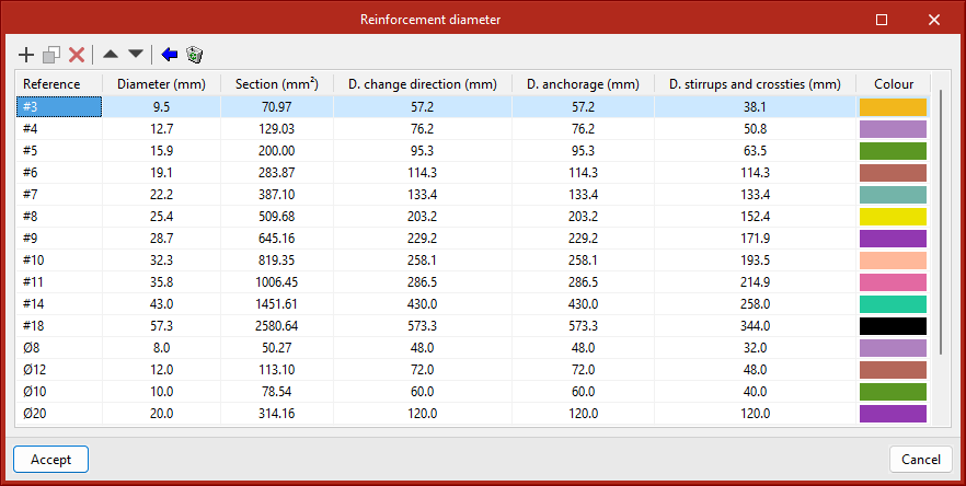
Reinforcement diameter
This library contains the bars used to define the reinforcement. For each type of bar, users must define the reference, diameter, section, internal bending diameters and representation colour. When importing data from other design programs, the imported bars will automatically be included in this table.
Bar bending
This library contains the available bar types or shapes. The program offers several predefined types.
‘Project reports’ options
This provides configuration options for the reports, including the possibility of displaying a summary of reinforcements per diameter, as well as defining a percentage of steel losses and the font size for the bend documents.
Configuration
Allows users to define the IFC representation and export options with the following options:
- Include the description of the bars in BVBS format
An additional parameter with the description of the bar in BVBS format is included in each bar. - Quantities
Additional parameters with length and weight are included for each bar.
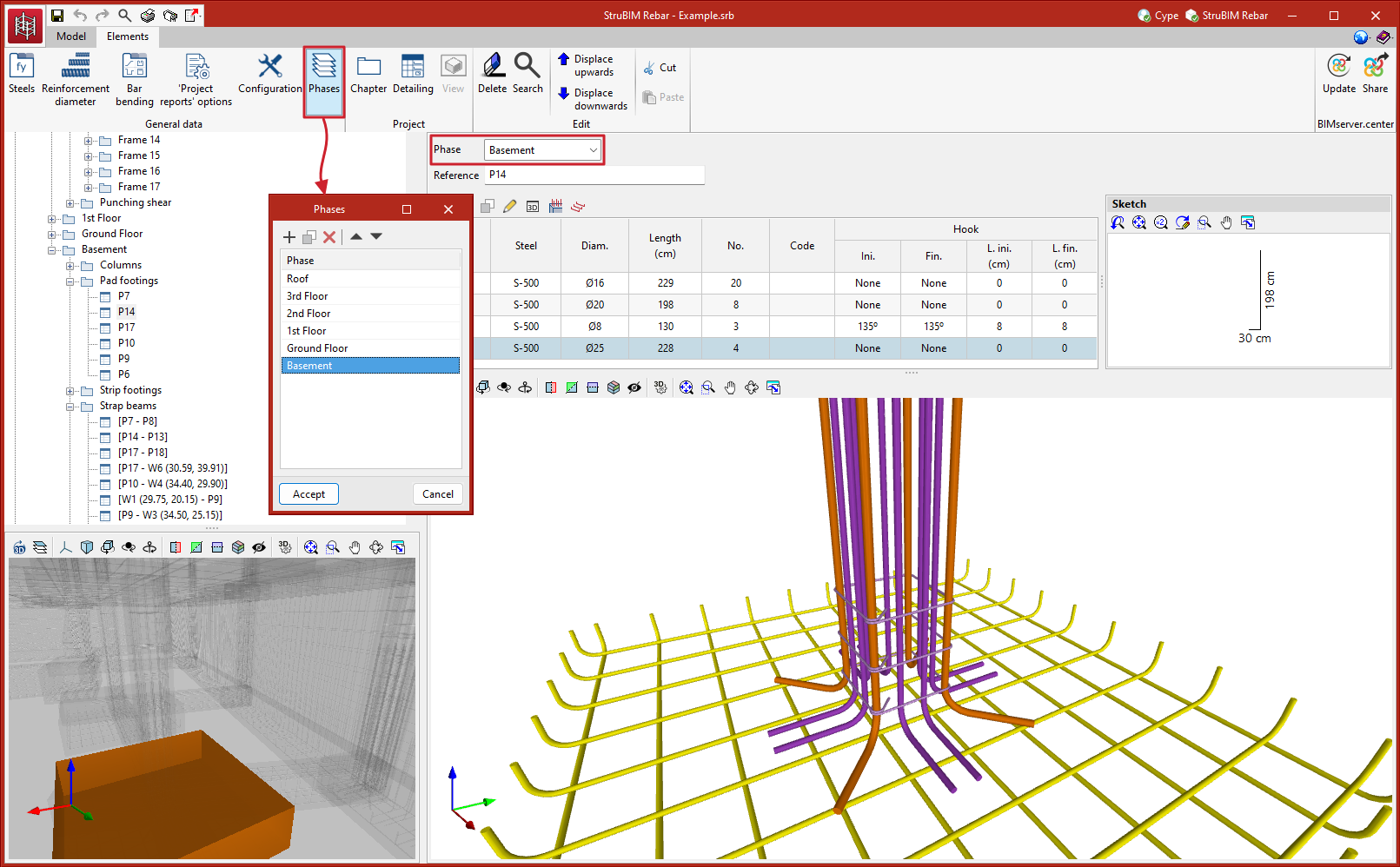
Phases
Allows users to sort and manage the elements by phases. This option generates an IFC file for each of the defined phases, containing the elements assigned to that phase.
When elements are imported from CYPECAD, a phase is generated for each floor and each element is assigned the equivalent phase to the CYPECAD floor to which it belongs.
Editing the model
Within the "Model" tab, in the "Edit" group of the main toolbar, users can find the main tools for editing the model.

The editing tools are as follows:
- Edit
Allows users to edit the detailing of an element. - Delete
Allows users to delete the detailing of a selection of elements. - Assign phase
Allows users to assign a phase to a selection of elements.
Measuring tools
Within the "Model" tab, in the "Measurement" group of the main toolbar, users can find the tools for measuring directly on the model.

These tools are as follows:
| Measure length | This allows lengths to be measured from one point to another. | |
| Measure area | This allows an area to be measured by specifying an area defined by a series of points. | |
| Measure angle | This allows an angle to be measured by specifying two points and a centre. | |
| Count the number of objects | This allows a number of elements to be counted. | |
| Measure the area of objects | Allows users to measure the area of an element by simply clicking on the object. | |
| Measure the volume of objects | Allows users to measure the volume of an element by simply clicking on the object. |
Project
Within the "Elements" tab, in the "Project" group of the main toolbar, there are tools for managing the chapter tree.

These tools are as follows:
- Chapter
Allows users to add chapters to the tree. Chapters are added to the selected chapter. The root chapter, "Project", contains the "Elements" and "Views" chapters. Detailing elements are added under "Elements" and views under "Views". - Detailing
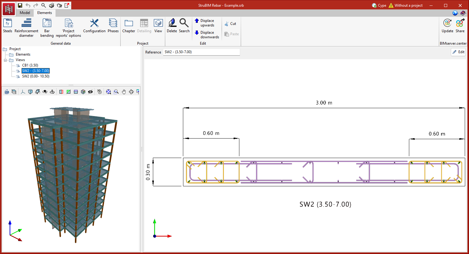
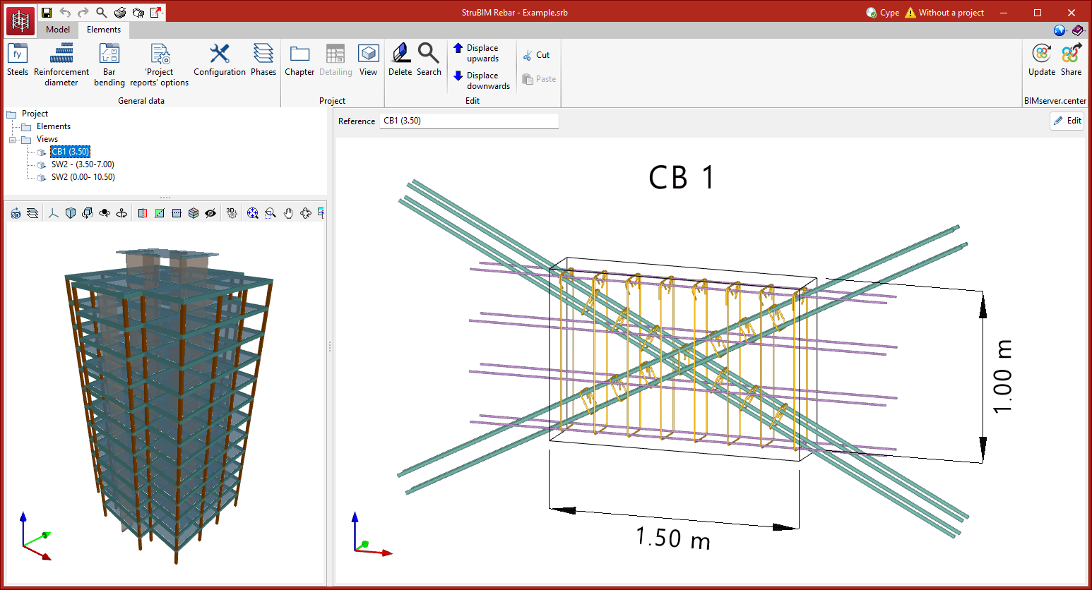
Allows users to add detailing to the selected chapter. Groups of bars can be added manually to this detailing. - View
Allows users to generate views of one or more detailing elements. Dimensions and notes can be inserted in these views. Furthermore, a view can be added to the selected chapter. When adding a view, the program asks users to select the detailing to be represented in this view.
Editing elements
Within the "Elements" tab, in the "Edit" group of the main toolbar, are the main tools for editing the elements.

These tools are as follows:
- Delete
Allows users to delete the selected element from the tree. - Search
Allows users to search the tree by reference. - Displace upwards and Displace downwards
These tools allow users to move the selected element (chapter, detailing or view) in the tree. - Cut
Allows users to cut the selected element. - Paste
Allows users to paste the element.
Results
StruBIM Rebar provides results in the form of reports, drawings, a BIM model in IFC and the export of information to the BIM project hosted on the BIMserver.center platform.
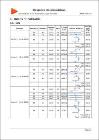
- Reports
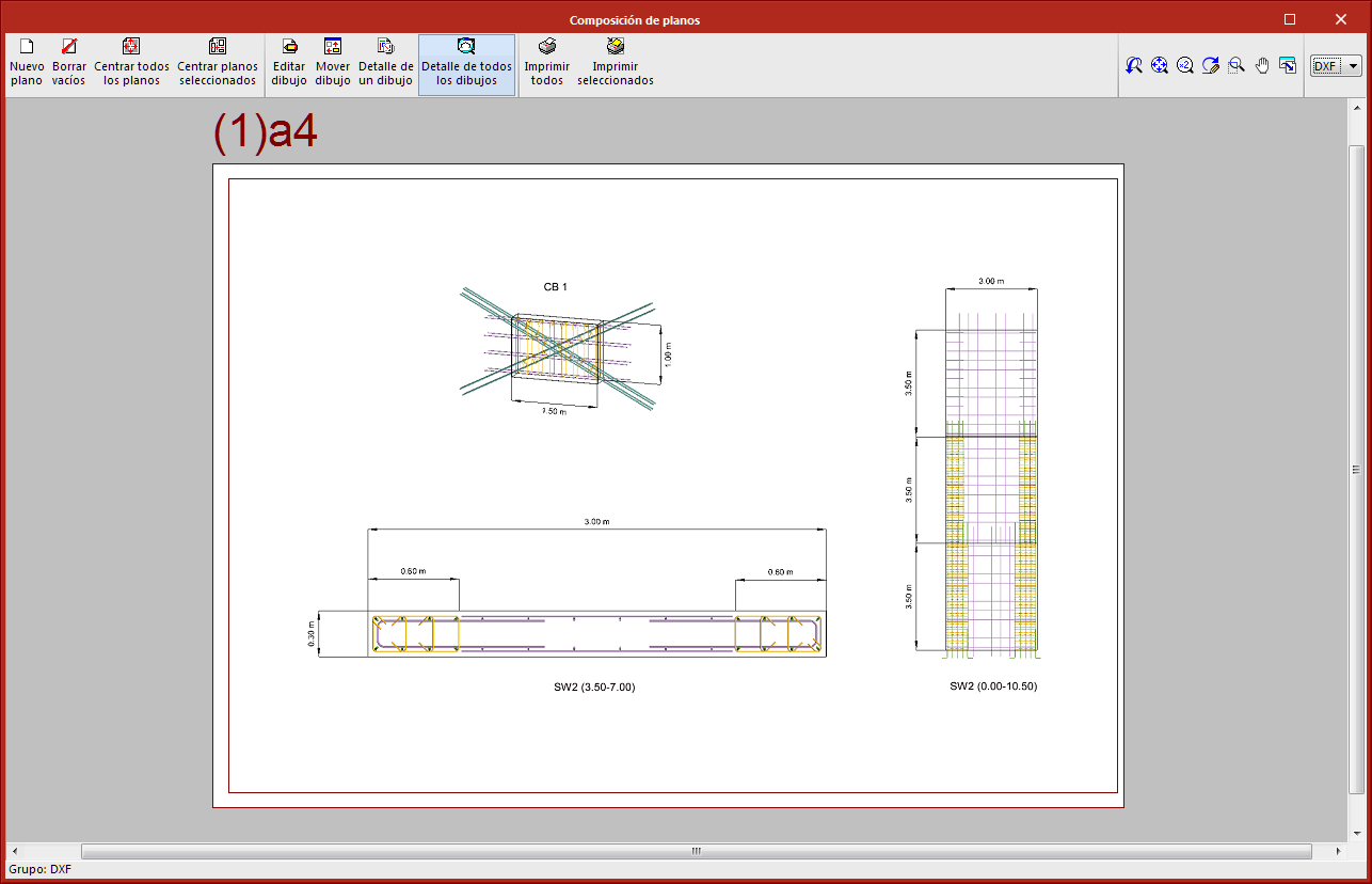
The program generates the detailing report of the elements of the project. - Drawings
The drawings that are generated by “StruBIM Rebar” include the views that have been created by users. - Export in IFC format
StruBIM Rebar allows the 3D model to be exported in IFC format. - Export in BVBS format
StruBIM Rebar allows the 3D model to be exported in BVBS format. The export can be performed for the complete model as well as for each detailing element.
Supported licenses and modules
StruBIM Rebar has a number of different modules that can be combined to enhance the tool's features.
SRC module: StruBIM Rebar Core
The SRC module is the basic module for operating StruBIM Rebar and is a prerequisite for operating the other modules.
SRW module: StruBIM Rebar – Shear Walls
The SRW module is used for importing shear walls designed and calculated with StruBIM Shear Walls in order to generate the detailing of their reinforcement.
SRV module: StruBIM Rebar – Coupling Beams
The SRV module is used for importing coupling beams designed and analysed with StruBIM Shear Walls to generate the detailing of their reinforcement.
SRZ module: StruBIM Rebar – Footings
The SRZ module is used to import footings designed and analysed with CYPECAD in order to generate the detailing of their reinforcement.
IFR module: Export reinforcement detailing (IFC and BVBS)
The IFR module allows the reinforcement detailing produced with StruBIM Rebar to be exported to IFC and BVBS formats.