The option “Copy elements” (Job > Copy Elements) allows users to copy a selection of elements to a new position. As of the 2015.e version, the same elements can be copied repeatedly without having to be reselected.


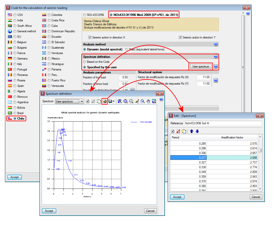
Improved code application. NCh433.Of1996 Mod.2009 (D°n°61. De 2011) (Chile)
Norma Chilena Oficial Diseño Sísmico de Edificions (Includes modifications of decree n° 61 (V. and U.) of 2011).
This code was already implemented in previous CYPECAD and CYPE 3D versions. Now, with the 2015.e version, a user seismic spectrum can be defined. A design spectrum must be defined to carry out the seismic analysis of the structure. Each seismic resistance code provides the criteria that are to be followed within a specific territory for the seismic action to be considered in the project. Nonetheless, the project designer can adopt, under his/her responsibility, different criteria to that established in the code. The program offers different ways to proceed for the use of either way. The design seismic spectrum can be:
- Calculated in accordance with that specified in the seismic code to be applied.
- Specified by users based on his/her criteria.
Shells in CYPE 3D
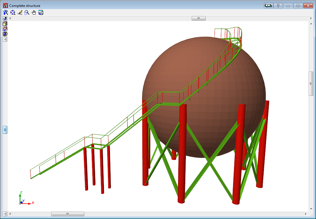
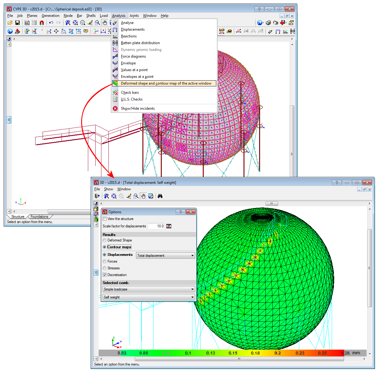
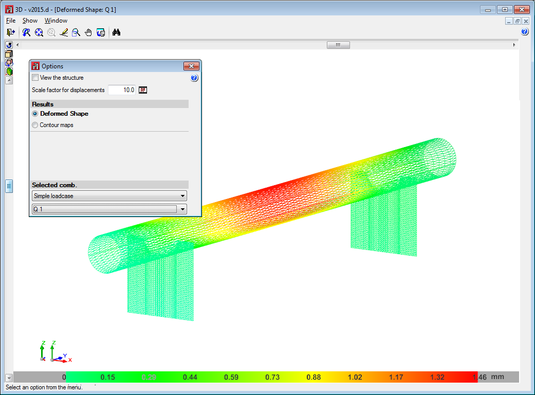
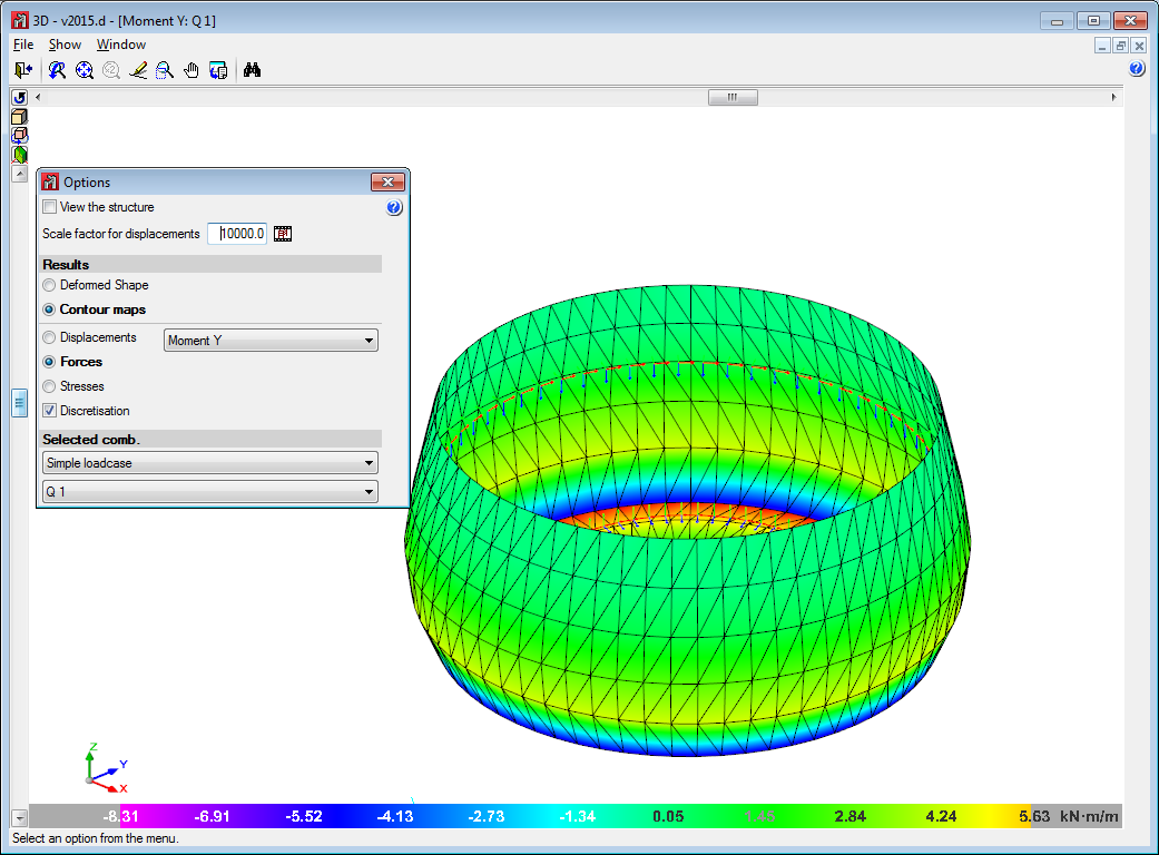
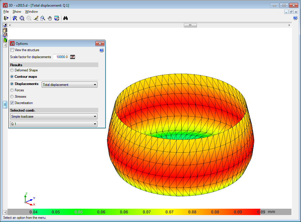
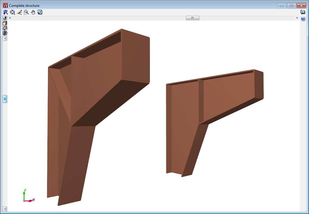
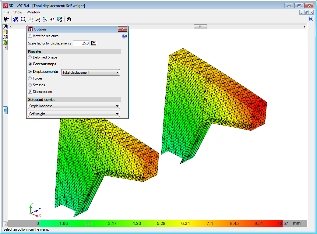
The 2015.d version of CYPE 3D allows users to define shells. Shells are flat two-dimensional elements with constant thickness and without openings, whose perimeter is defined by a polygon.
Shells are introduced in the global stiffness matrix of the structure using a three-dimensional finite element model composed of six-node (quadratic) triangular flat shells. The type of element used is based on the overlap of two locally decoupled elements: one provides the axial stiffness (membrane forces) and the other the bending stiffness (panel forces).
The following properties can be defined for each shell:
- Thickness and subgrade modulus
In the local Z axis direction - Material
Concrete, rolled steel, cold-formed steel, aluminium and generic material (by specifying the modulus of elasticity and Poisson coefficient). - Position
With respect to the introduction plane - Discretisation
The density of the mesh can be controlled by defining the maximum size of the triangle in the local x and y axes. - Direction of the axes
- Internal fixity
Internal fixity between the edges and other elements of the structure. - External fixity
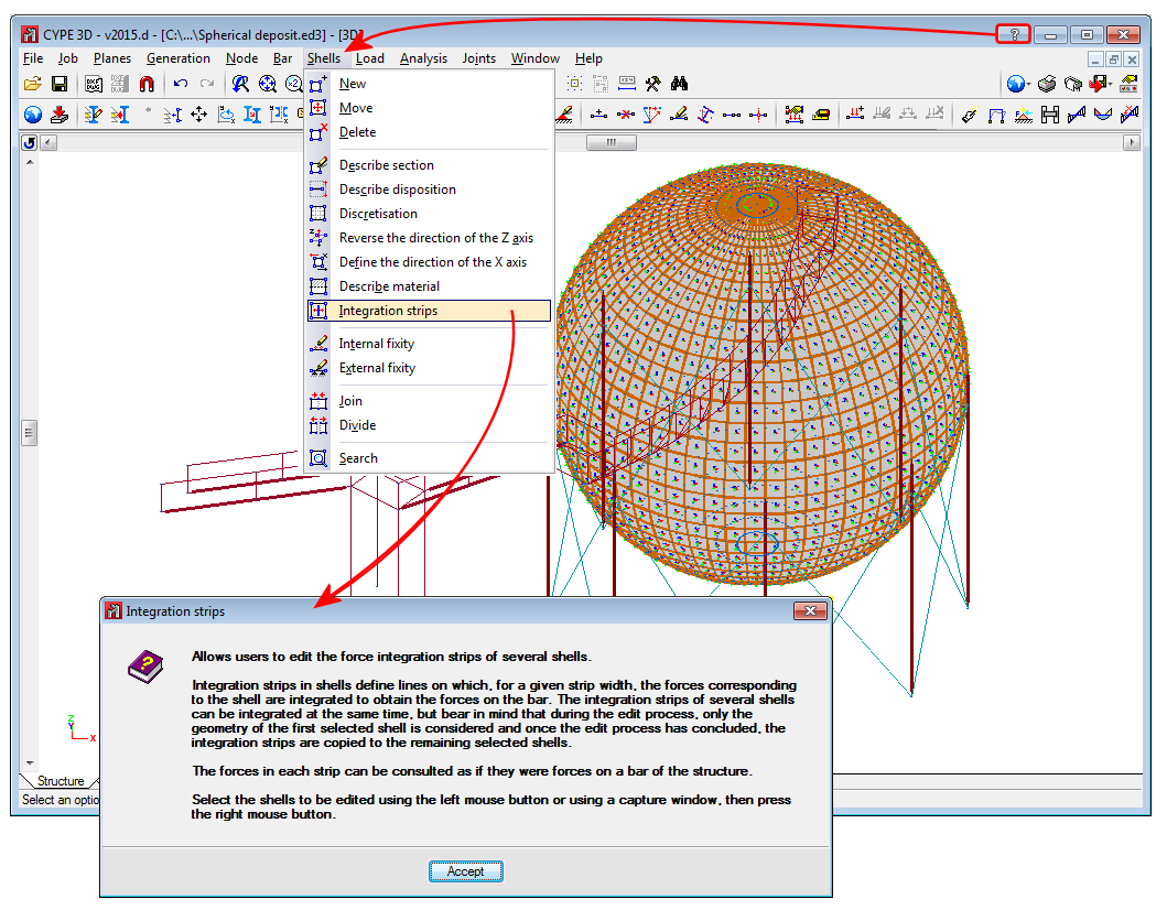
It is also possible to define the external fixity of the edges, but in this case, the fixity is applied to all the shells sharing that edge. The possible external fixity configurations are the same as those available for the nodes of CYPE 3D. - Integration strips
Integration strips in shells define lines on which, for a given strip width, the forces corresponding to the shell are integrated to obtain the bar forces.
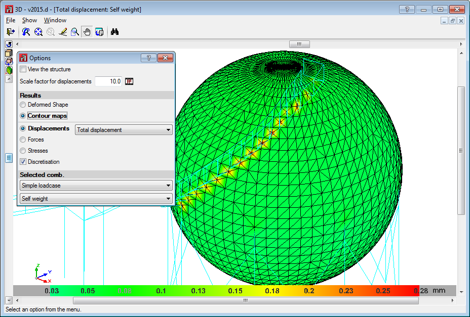
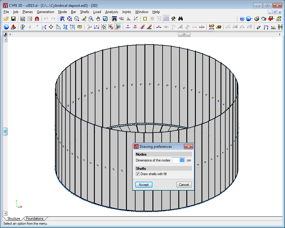
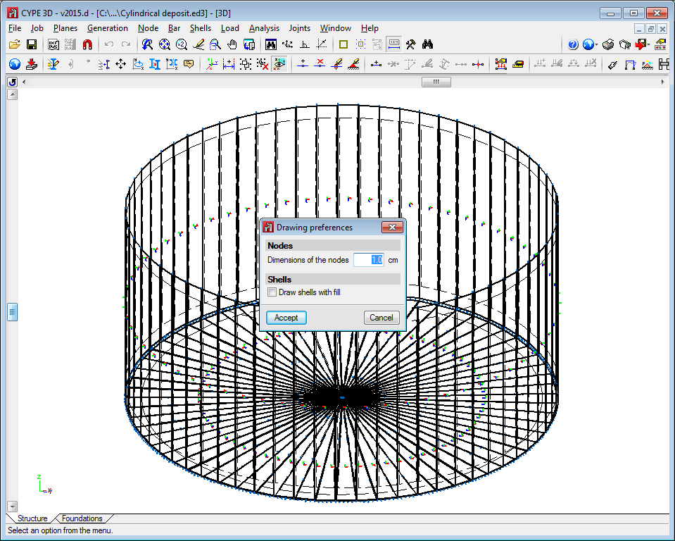
The program contains an option which users can use to view the shells in 3D. They can be viewed filled in or simply their outline can be displayed. This can be indicated in the drawing preferences option in the Job menu.
To be able to use shells in CYPE 3D, users must have the permits required to use CYPE 3D.
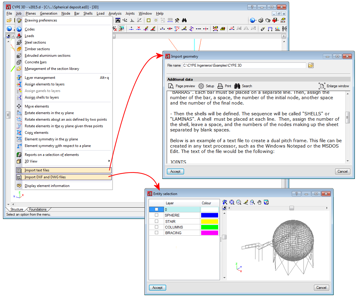
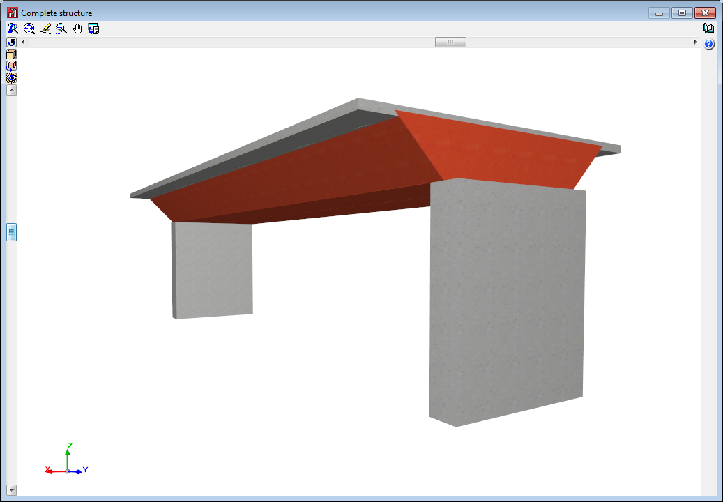
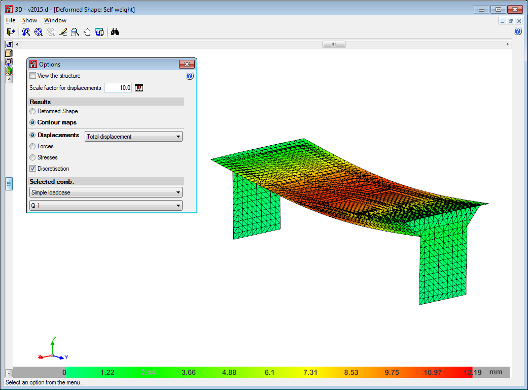
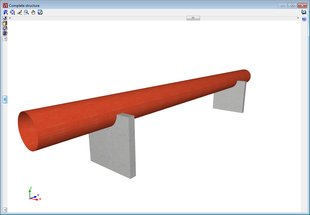
Below are some examples of structures created with shells in CYPE 3D:
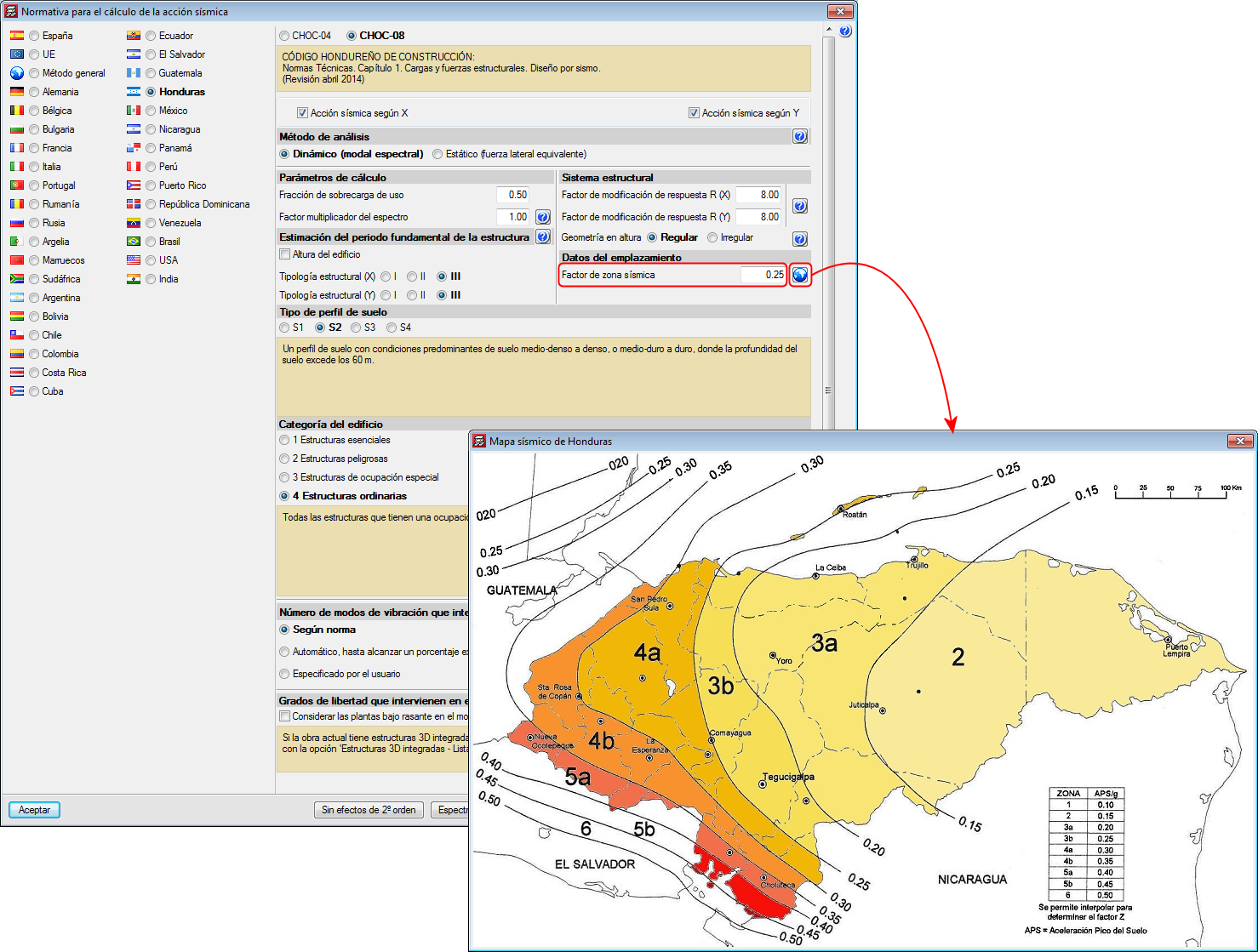
Improved code application. CHOC-08 (Honduras)
Código Hondureño de la Construcción. Normas Técnicas. Capítulo 1. Cargas y fuerzas estructurales. Diseño por Sismo
This code was already implemented in CYPECAD and CYPE 3D in previous versions. Now, with the 2015.d version, the new seismic map (which displays zones 3, 4 and 5) has been implemented and values between 0.10 and 0.60 can be introduced for the “Factor de zona sísmica” (Seismic zone factor).
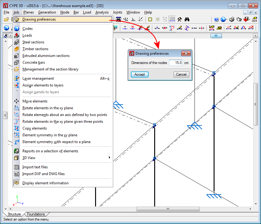
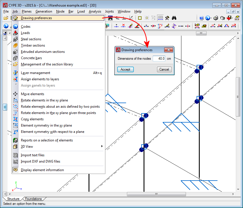
Node dimensions
The size of the represented nodes can now be defined (Job > Drawing preferences).
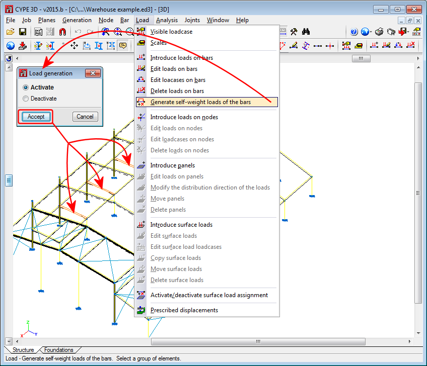
Generation of the self-weight of bars
Since the first version of Metal 3D (CYPE 3D as of the 2014.a version), the self-weight of the sections that are introduced are automatically generated by the program, regardless of the type of material that has been selected: steel, aluminium, timber, or any other user-defined material (except for steel bars defined as ties, for which the self-weight of the section is not taken into account).
As of the 2015.b version, the automatic generation of the self-weight of the sections that have been introduced is optional. A new option has been implemented: Generate self-weight loads of the bars (Load menu). When this option is selected, a dialogue box opens where the self-weight of the bars, selected after accepting the dialogue box, can be activated or deactivated.
CYPE 3D generates the self-weight of all the bars by default. The self-weight of bars defined as ties is still not taken into account, furthermore, the option “Generation of the self-weight of bars” does not allow for bars defined as ties to be selected.