Update history​​

CYPE 3D

In version 2025.c, new options have been added to the "Help" menu of all CYPE apps, providing direct links to key resources on the CYPE website. These options make it easier to access to useful information and Technical Support, improving the overall experience of using the program.

The new options are the following:

  • Technical support: This link provides information on the different ways of contacting the CYPE Technical Support team to clarify any queries, obtain customised assistance and solve any problem related to the apps.

  • User community: This option provides access to the CYPE user community, where users can share experiences, ask questions and discuss solutions with other professionals using the same tools. This community encourages the exchange of knowledge and best practices, helping to make the most of the program's features.

  • Learning resources: This link leads to a collection of learning resources, such as tutorials, manuals, videos and articles, designed to help you understand and use CYPE apps more efficiently. These materials are designed for all levels of experience, from beginners to advanced users, and are an excellent source of information to expand skills and technical knowledge.

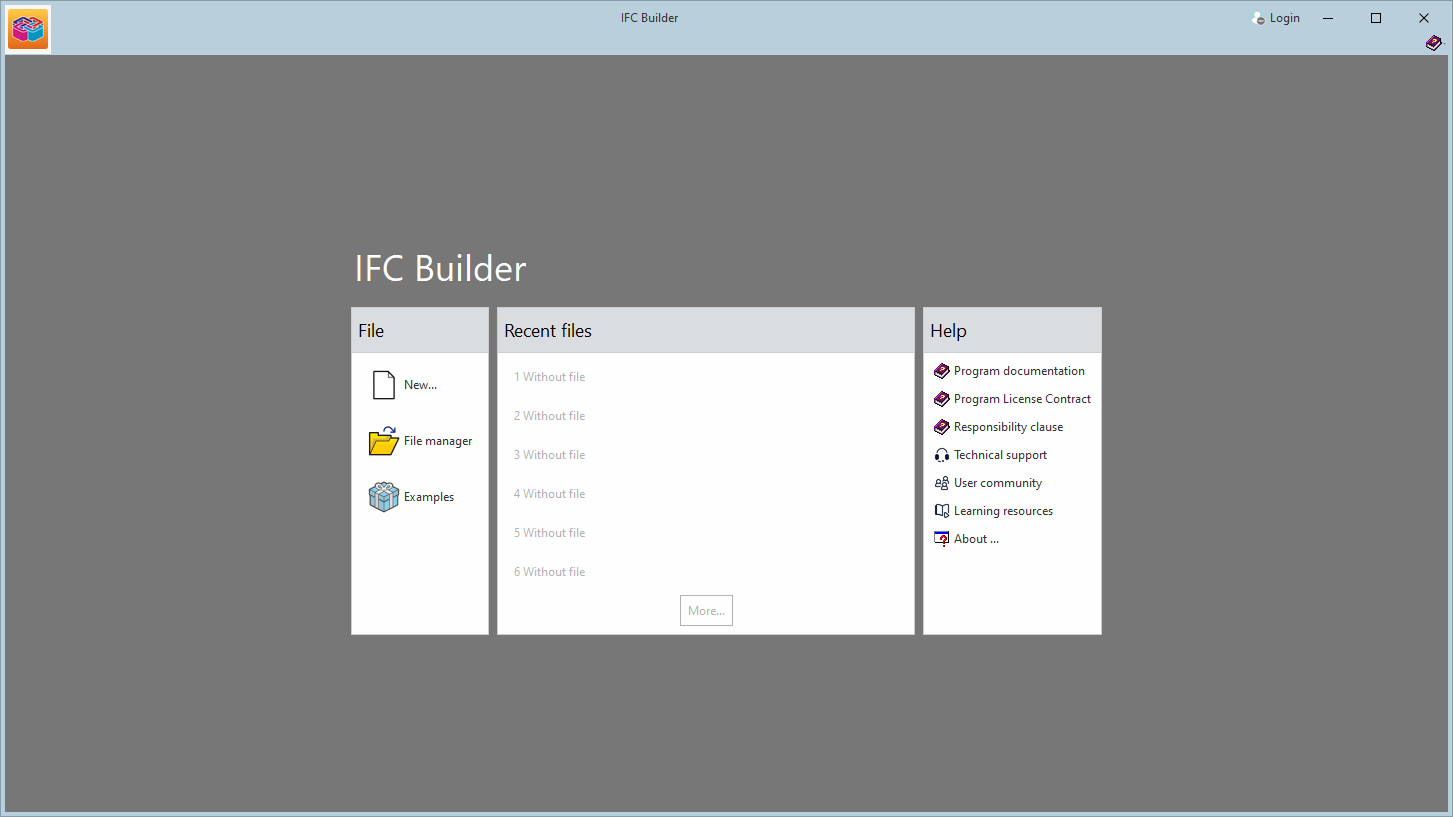
These new additions make it easier to access information and provide the necessary support to improve the users' experience with the apps and to encourage professional development.

In version 2025.c, the generation of reports in CYPE 3D will be faster, as memory usage optimisations have been implemented during the process.

As of version 2025.c, users can select a language other than the one used in the program to obtain reports and drawings. For this purpose, the "Language for reports and drawings" option has been implemented, which is accessible from several dialogue boxes in the program as shown in the image.

Please note that references to certain elements of the job, such as group and floor plan names, will be in the language they were entered in. The same applies to general settings of the program, such as the names of "Floor plans", or the chapters of "Customised reports".

In version 2025.c, the calculation of the sinking load in deep foundations using reinforced concrete piles has been implemented for the "CYPECAD", "CYPE 3D" and "Foundation elements" programs. This implementation has been included in the new "Piles: Calculation of sinking load" module.

This module complements the design of deep foundations using pile caps, allowing users to verify the bearing capacity of the piles under different load conditions, considering the characteristics of the soil and the pile itself.

The program allows users to define several ground types, including cohesive soils, granular soils and rock formations. Each soil type can be configured with its specific geotechnical properties, allowing a customised analysis of the site characteristics. Furthermore, the defined soils can be reused, which optimises the modelling and design process. Piles can be either precast or cast-in-place, with square or circular cross-sections.

The resistance to sinking is obtained by considering the resistance per tip and shaft of the soil layer in contact with the pile. The calculation method used is based on analytical formulations based on the Mohr-Coulomb equation taken from the existing specific technical specifications. The verification has been implemented for the entire set of codes available in the CYPECAD, CYPE 3D and Foundation elements programs.

The "Check "option, accessible from the editing panel of the foundation elements, allows users to consult the calculations made to verify the safety of the piles.

To use this module, the following permissions must be included in the license, depending on the program where it is to be used:

  • In CYPECAD
    "CYPECAD", “Pile caps” and “Piles: Calculation of the sinking load”.
  • In CYPE 3D
    "CYPE 3D", “Pile caps” and “Piles: Calculation of the sinking load”.
  • In Foundation elements
    "Foundation elements” and “Piles: Calculation of the sinking load”.

In version 2025.c, the preview for moving dockable windows within the apps has been improved. Now, when dragging a dockable window, the preview of its docked position is displayed transparently, allowing a clearer view of the underlying work area.

This new feature makes it easy to find the optimal location for each dockable window without obstructing important elements or losing sight of relevant project information. It also provides a smoother and more modern visual experience, aligned with best practices in user interface design.

Version 2025.c of the CYPE apps includes the following improvements in the management of DXF and DWG file templates:

  • Reading DXF/DWG files with updated version
    As of version 2025.c, CYPE apps can read DXF/DWG files up to AutoCAD® version 2025.

  • Improved template preview
    Advanced graphic management has been implemented in the template selection and transformation panels to optimise the template drawing preview window and facilitate the movement of the drawing from this panel.

  • Simultaneous transformations on the template
    The application of the following transformations on an imported template has been improved:
    • Selecting the visible area of the template
    • Changing the coordinate origin of a template
    • Adjusting the scale of a template

As of version 2025.c, the "Drawing layouts" panel uses hardware acceleration for drafting drawings. This implementation allows users to represent and move the model more smoothly.

This panel is present in several CYPE programs, although hardware acceleration is much more noticeable in programs and projects with multiple elements (CYPECAD, CYPE 3D, CYPECAD MEP, etc.).

Up until version 2025.c, when carrying out the design considering the fire resistance and specifying a type of fireproof cladding, CYPE 3D checked the bars by indicating the minimum required thickness of this cladding. In version 2025.c, tools allowing users to edit, design and check the thicknesses of the fireproof cladding have been implemented.

In the "Bar" menu, in the "Fire resistance" section, the following options can be accessed:

  • Required resistance / Protective coating
    In this section, the program allows users to define a particular configuration for the fire resistance check of a selection of bars.
  • Exposed sides
    This section defines the sides of the bars exposed to fire. This section, together with the "Required resistance / Protective coating" section, was combined in a single panel in previous versions.


  • Coating thickness
    This new tool allows users to define the thickness of the fire-resistant coating applied to the bars.
  • Groups
    This now includes the ability to design the thicknesses of the fireproof coating. The design can be carried out by matching the thickness of the bars belonging to the same group, among other options. This option allows the creation of design groups, which can be composed of one or several tags.

In the "Analysis" menu, the "Design of the thickness of the fireproof coating" tool is added, which includes the following options:

  • Minimum critical temperature
    Defines a minimum critical temperature for designing the thickness of the coating.

  • Minimum cover thickness
    Sets a minimum thickness for the coating.

  • Maximum cover thickness
    Sets a maximum thickness for the coating.

  • Thickness increase when designing
    Specifies the thickness increment to be used by the program during the design process.

  • Matching the coating
    • Calculates the thickness required for each bar. When this option is selected, the program assigns the required coating thickness to each bar.
    • Levels the thickness of all the bars. When this option is activated, the program matches the thickness of the coating on all the bars, taking as a reference the thickness of the most unfavourable bar
    • Matches the thickness of the bars with the same section. With this option, the program matches the thickness of the cladding of the bars with the same section, applying the thickness of the most unfavourable bar.
    • Matches the thickness of bars belonging to the same group. This option allows users to match the thickness of the cladding of the bars belonging to the same group, using the thickness of the most unfavourable bar.

In this new 2025.c version of CYPE 3D, the coating thickness check is also implemented.

In the drawings section, options for tagging the required strength, protective coating, coating thickness and critical temperature on the bars are also included.

Up until now, the "Pin ends" tool in the "Bar" menu only allowed users to pin one or both ends of each bar individually.

As of version 2025.c, this tool has incorporated an option for selecting multiple bars, which automatically pins the two ends of all selected bars.

This selection can be carried out one bar at a time, using a rectangular selection area or using the new filtering tool, which makes the process considerably easier when the ends of multiple bars need to be pinned.

In version 2025.c of CYPE 3D, a new tool is implemented that allows users to define bracing pairs for buckling analysis.

The linear buckling analysis is carried out for each combination by eliminating the non-linear elements that are not involved and transforming those that are involved into equivalent linear elements. In this process, when two bars with "Only tension" behaviour form a braced frame and both bars are compressed in the same load case, the program transforms the behaviour of these bars to linear and reduces their axial stiffness by half. In situations where a portal frame is braced by two non-intersecting braces if both are compressed in a load case, the program deletes them before carrying out the buckling analysis, so the results of the buckling analysis are obtained without considering these bars in tension.

From version 2025.c, with this new tool, bracing pairs can be defined. If both bars in tension in a pair are compressed in a load case, they will be retained in the buckling analysis, reducing their axial stiffness by half, similar to the way the program does it automatically for bars in tension forming a braced frame.

Up until version 2025.c, loads were always represented with a size proportional to the load value. In CYPE 3D version 2025.c, another option is implemented to represent loads with a size proportional to a fixed value.

When the values of the loads are very different, the representation proportional to the value of the load may cause some loads to look very large and others very small. In these cases, this new option is very useful, as it allows a uniform representation.

In version 2025.c, the option to display loads with fill has been added. This feature is available in the dockable panel "View options".

When the option is deactivated, the loads are displayed in the same way as in previous versions. When enabled, the loads are drawn as filled, using the identifying colour corresponding to the loadcase.

CYPE Mentor