Update history​​

CYPE 3D

In previous versions of the program, the automatic calculation of the susceptibility to local buckling due to compression was already included assuming that each of the flat elements making up the section buckled in an isolated manner (independent from the rest), and the possibility was included, for any other type of buckling other than the individual type to be considered, to modify the local buckling coefficient which affects the slenderness parameter associated to each element. In this new version, the automatic calculation of the susceptibility to local buckling due to compression considering the possibility that several elements can buckle together as if they were a single element, is also included, hence combined buckling modes are obtained. The program is able to detect and analyse the buckling in a group of elements in the following cases:

  • Element sequence with all their ends aligned along a straight line
  • Element sequence with all their ends arranged along a circumference arc with small curvature
  • Element sequence making up a cell

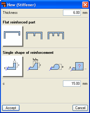
The combined buckling is also studied if the elements making up the section have been stiffened, which is commonly referred to as buckling due to distortion. Regarding the stiffened elements, a new assistant has been implemented for the design with standard reinforcement in accordance with that exposed in EC9.

The following rolled steel codes have been implemented for the five joints modules (Joints I, Joints II, Joints III, Joints IV and Joints V):

  • ANSI/AISC 360-05 (LRFD) (USA – International )
  • IS 800: 2007 (India)

NCh433.Of1996 Modified in 2009 (Chile). Official Chilean Code. Seismic Design of Buildings.

Implemented in CYPECAD and Metal 3D. Includes the emergency modifications presented in the Decree Nº117 (V. and U.) of the Diario Official de Chile of the 14th February 2011.

NSR-10 (Colombia): Reglamento Colombiano de Construcción Sismo Resistente
Code implemented in CYPECAD and Metal 3D.
The NSR-10 code substitute the outdated NSR-98 code. Nonetheless, any of the two codes can be used in CYPECAD and Metal 3D.

  • IS 456: 2000 (ACI318M-08) (India): Plain and Reinforced Concrete – Code of Practice.
    Implemented in CYPECAD and Metal 3D.
    Includes materials, steel bar diameters and load combinations of the code with the design criteria of the ACI 318M-08 (USA) code. The design criteria of the IS 456: 2000 code will be included in upcoming updates of the 2011 version.

CFE 2008 (Mexico): Manual de diseño de Obras Civiles. Diseño por sismo. Comisión Federal de Electricidad. México 2008.
Code implemented in CYPECAD and Metal 3D.

DIN 18800:2008-11 (Alemania): Deutsches Institut für Normung. Stahlbauten.
Code implemented in CYPECAD and Metal 3D for the following sections:

Rolled and welded steel

  • I
  • C
  • L
  • Rectangular hollow section
  • Circular hollow section

Cold-formed steel

  • C and stiffened C
  • L and stiffened L
  • Rectangular hollow section
  • Circular hollow section

The following elements have been implemented when exporting to Tekla structures:

  • Concrete beams and columns of CYPECAD, and concrete bars of Metal 3D and integrated 3D structures of CYPECAD. The elements that are exported have rectangular, circular, T or L sections.
  • Special extruded aluminium sections
  • Trims at hollow section ends processed by the new Joints V module.
    These elements are exported as macros type “Tube-Saddle+Hole” for versions 15.0 SR1 and 16.0 of Tekla Structures.

An optimisation in the analysis procedure now reduces the time taken to analyse structures with applied earthquake loads.

Metal 3D has incorporated the possibility to define Ties between nodes. The ties between the nodes are used to indicate that two or more nodes have the same displacements for all the loadcases. This displacement can be in one, two or three directions in accordance with the X, Y and Z global axes. The number corresponding to each group of nodes whose displacements have been tied is displayed on screen.

Bear in mind that for two or more nodes to have the same displacement, an element or construction arrangement must be present in the structure that will effectively materialise the equal displacement hypothesis.

Ties cannot be assigned to nodes that form part of braced frames when the tied displacement has its projection on the plane of the braced frame.

The C1 coefficient for the lateral buckling critical moment can now be defined. Generally speaking, each code offers specific values for these coefficients associated with different bending moment distributions.

The aluminium extrusion process has the advantage that as well as being able to obtain standard transverse aluminium alloy sections, specific designs can also be obtained. As of previous versions, the program has allowed users to design structures using standard extruded aluminium sections, i.e. those that are usually found in a manufacturer’s catalogue. As of the 2011.a version, one of the new features is the Extruded aluminium section editor, which allows for the design and check of aluminium alloy bars with specific transverse sections.

The Special aluminium section option has been included in the Describe section dialogue box (Bar > Describe section > select the bar on screen > right click with mouse button > Special aluminium section). Upon clicking the button, a dialogue box opens with options to create, copy, edit and manage a library of special extruded aluminium sections. Using the create button (or edit button, once special sections have been defined), the extruded aluminium section editor is displayed on screen.

The specific design of the section increases the range of available transverse sections, allowing for an optimum combination which simplifies the constructions process of the structure, with mechanical properties which maximise the resistance effectiveness with minimum weight. The program also offers the possibility of stiffened sections without having to use composite sections, which avoids having to weld or bolt the components.

Using the extruded aluminium sections editor, any section can be created: open, with cells, made up of thin walled flat elements… and used in the structural analysis to proceed with the resistance calculation, including the corresponding check reports.

The editor offers information on the mechanical and torsional properties of the gross section, required for the structural analysis, which is updated after any modifications have been carried out. Properties displayed include the section’s area, moment and product of inertia, torsion module, warping constant and shear centre coordinates.

Using the calculated resistance of the sections created with the editor, the section is checked for the forces derived from the structural analysis. The analysis incorporates an automatic calculation of the section’s susceptibility against the local buckling of the thin walled elements making up the transverse section, assuming each one buckles independently. The local buckling coefficient which affects the slenderness parameter of each element can be edited and so be able to consider other buckling modes. The section is classified based on the previous analysis, and with it, the effective properties, elastic or plastic, are obtained which will then be used for the resistance checks.