Update history​​

CYPE 3D

The following elements have been implemented when exporting to Tekla structures:

  • Concrete beams and columns of CYPECAD, and concrete bars of Metal 3D and integrated 3D structures of CYPECAD. The elements that are exported have rectangular, circular, T or L sections.
  • Special extruded aluminium sections
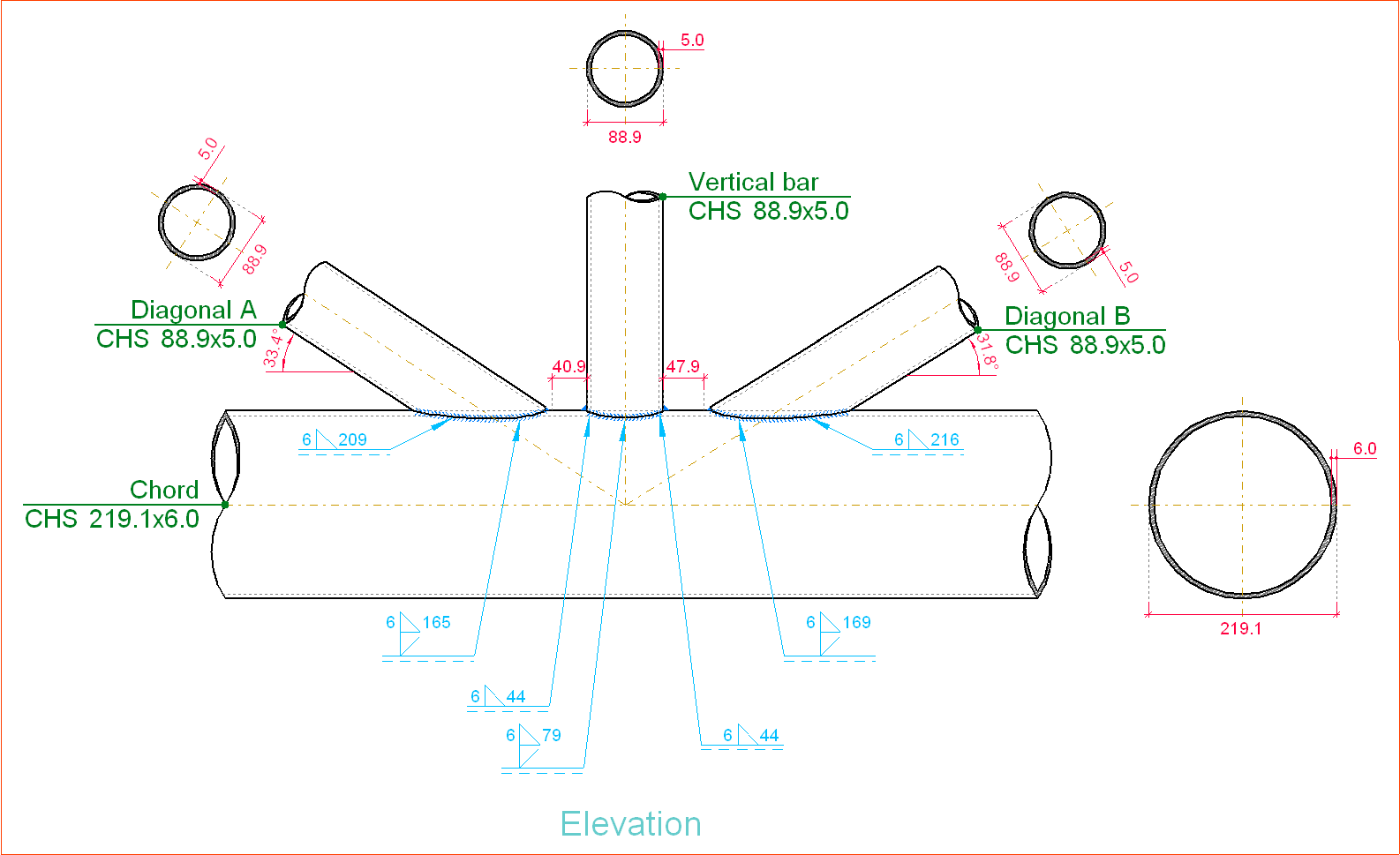
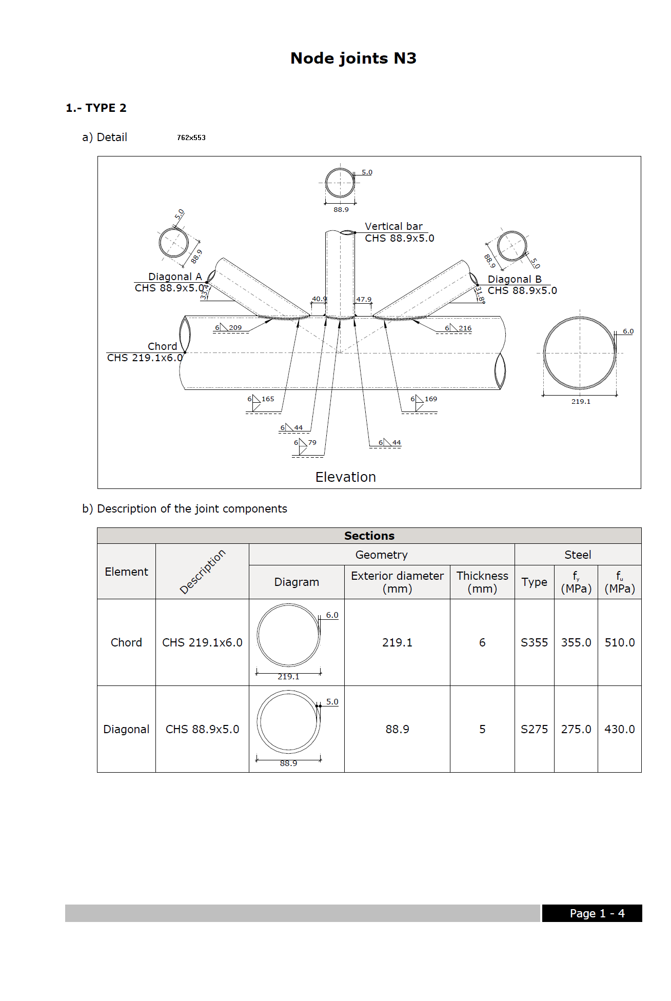
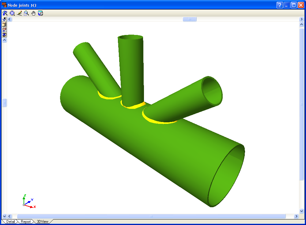
  • Trims at hollow section ends processed by the new Joints V module.
    These elements are exported as macros type “Tube-Saddle+Hole” for versions 15.0 SR1 and 16.0 of Tekla Structures.

An optimisation in the analysis procedure now reduces the time taken to analyse structures with applied earthquake loads.

Metal 3D has incorporated the possibility to define Ties between nodes. The ties between the nodes are used to indicate that two or more nodes have the same displacements for all the loadcases. This displacement can be in one, two or three directions in accordance with the X, Y and Z global axes. The number corresponding to each group of nodes whose displacements have been tied is displayed on screen.

Bear in mind that for two or more nodes to have the same displacement, an element or construction arrangement must be present in the structure that will effectively materialise the equal displacement hypothesis.

Ties cannot be assigned to nodes that form part of braced frames when the tied displacement has its projection on the plane of the braced frame.

The C1 coefficient for the lateral buckling critical moment can now be defined. Generally speaking, each code offers specific values for these coefficients associated with different bending moment distributions.

The aluminium extrusion process has the advantage that as well as being able to obtain standard transverse aluminium alloy sections, specific designs can also be obtained. As of previous versions, the program has allowed users to design structures using standard extruded aluminium sections, i.e. those that are usually found in a manufacturer’s catalogue. As of the 2011.a version, one of the new features is the Extruded aluminium section editor, which allows for the design and check of aluminium alloy bars with specific transverse sections.

The Special aluminium section option has been included in the Describe section dialogue box (Bar > Describe section > select the bar on screen > right click with mouse button > Special aluminium section). Upon clicking the button, a dialogue box opens with options to create, copy, edit and manage a library of special extruded aluminium sections. Using the create button (or edit button, once special sections have been defined), the extruded aluminium section editor is displayed on screen.

The specific design of the section increases the range of available transverse sections, allowing for an optimum combination which simplifies the constructions process of the structure, with mechanical properties which maximise the resistance effectiveness with minimum weight. The program also offers the possibility of stiffened sections without having to use composite sections, which avoids having to weld or bolt the components.

Using the extruded aluminium sections editor, any section can be created: open, with cells, made up of thin walled flat elements… and used in the structural analysis to proceed with the resistance calculation, including the corresponding check reports.

The editor offers information on the mechanical and torsional properties of the gross section, required for the structural analysis, which is updated after any modifications have been carried out. Properties displayed include the section’s area, moment and product of inertia, torsion module, warping constant and shear centre coordinates.

Using the calculated resistance of the sections created with the editor, the section is checked for the forces derived from the structural analysis. The analysis incorporates an automatic calculation of the section’s susceptibility against the local buckling of the thin walled elements making up the transverse section, assuming each one buckles independently. The local buckling coefficient which affects the slenderness parameter of each element can be edited and so be able to consider other buckling modes. The section is classified based on the previous analysis, and with it, the effective properties, elastic or plastic, are obtained which will then be used for the resistance checks.

Composite sections made up of simple sections which are already implemented can be used with the following codes: AISI/NASPEC-2007 (LFRD) (USA), AISI/NASPEC-2007 (LFRD) (Mexico) and CAN/CSA S136-07 (Canada) (as of the 2011.a version). The simple sections and their corresponding composition to create composite sections are:

  • For simple cold-formed C and stiffened cold-formed C sections:
    • Double welded in a box
    • Double in a box with batten plates
    • Double in a box with generic joint
    • Double welded in I
    • Double in I with plates
    • Double in I with generic joint
  • For Rectangular cold-formed box and Square cold-formed box
    • Double with generic joint
    • Four with generic joint
  • Cold-formed angle and Symmetrical cold-formed angle
    • Double welded in a box
    • Double in a box with generic joint
    • Double welded in T
    • Double in T with generic joint
    • Double in U with generic joint
    • Double in cross with generic joint
  • Channel with stiffened web
    • Double welded in a box
    • Double in box with cover plates
    • Double in box with batten plates
    • Double in box with generic joint
    • Double welded in I
    • Double in I with plates
    • Double in I with generic joint
  • Eurocode 3
    The corrections undertaken by the CEN (European Committee for Standardization) have been implemented in the following documents (as of the 2011.a version)
    • EN 1993-1-1:2005/AC:2009
    • EN 1993-1-2:2005/AC:2009
    • EN 1993-1-3:2006/AC:2009
    • EN 1993-1-5:2006/AC:2009
    These implementations affect the use of Eurocode 3 for any of the countries that may be selected with this code (International, Bulgaria, France and Portugal).
    The following National documents of Eurocode 3 for France have been implemented:
    • NF EN 1993-1-2:2005/NA:2007
    • NF EN 1993-1-3:2007/NA:2007
    • NF EN 1993-1-5:2007/NA:2007

Eurocode 3
The corrections undertaken by the CEN (European Committee for Standardization) have been implemented in the following documents (as of the 2011.a version)

  • EN 1993-1-1:2005/AC:2009
  • EN 1993-1-2:2005/AC:2009
  • EN 1993-1-5:2006/AC:2009
  • EN 1993-1-8:2005/AC:2009

These implementations affect the use of Eurocode 3 for any of the countries that may be selected with this code (International, Bulgaria, France and Portugal).

The following National documents of Eurocode 3 for France have been implemented:

  • NF EN 1993-1-2:2005/NA:2007
  • NF EN 1993-1-5:2007/NA:2007

CPE INEN 5:2001 (Ecuador)
Construction code of Ecuador
General Design Requirements: Seismic danger, Design Spectrum and Minimum Calculation Requirements for Seismic-Resistant Design.
Implemented in CYPECAD and Metal 3D (as of the 2011.a version).

As of the 2011.a version, the 3D views of CYPECAD and Metal 3D contain a new option which displays elements with textures resembling the real colours of the material they are made out of. The user can choose to represent the 3D view with or without the materials:

  • Without materials
    Displays the materials that existed until now, which differentiated the elements of the 3D view, even if they consisted of the same material.
  • With materials
    Displays the elements of the 3d view with textures which resemble their real colours.

The Advanced design of surface foundations module complements the Footings and Pile caps modules when these are used in CYPECAD. Allows for the design of foundations composed of footings and pile caps with special element intersections (strap and tie beam intersections), geometrical trimming of footings, and application of line, point and surface loads on footings, pile caps and strap and tie beams. In the case of Metal 3D, this module only allows for trimming of the footing geometry to be carried out.

More information on this module can be found at:  Advanced design of surface foundations

The Joints V. Flat trusses with hollow structural sections module for CYPECAD, its Integrated 3D structures and Metal 3D, carries out an automatic analysis and design of coplanar hollow structural section connections, like those which are usually provided in flat trusses.

More information on this module can be found at: Joints V. Flat trusses with hollow structural sections.

CYPE Mentor