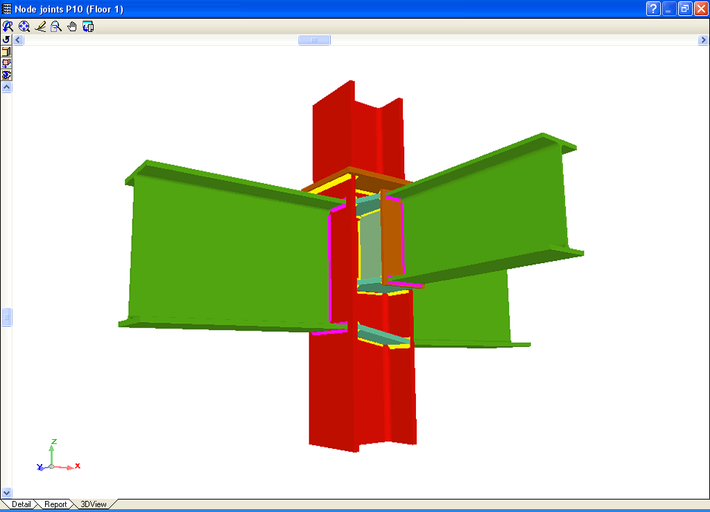
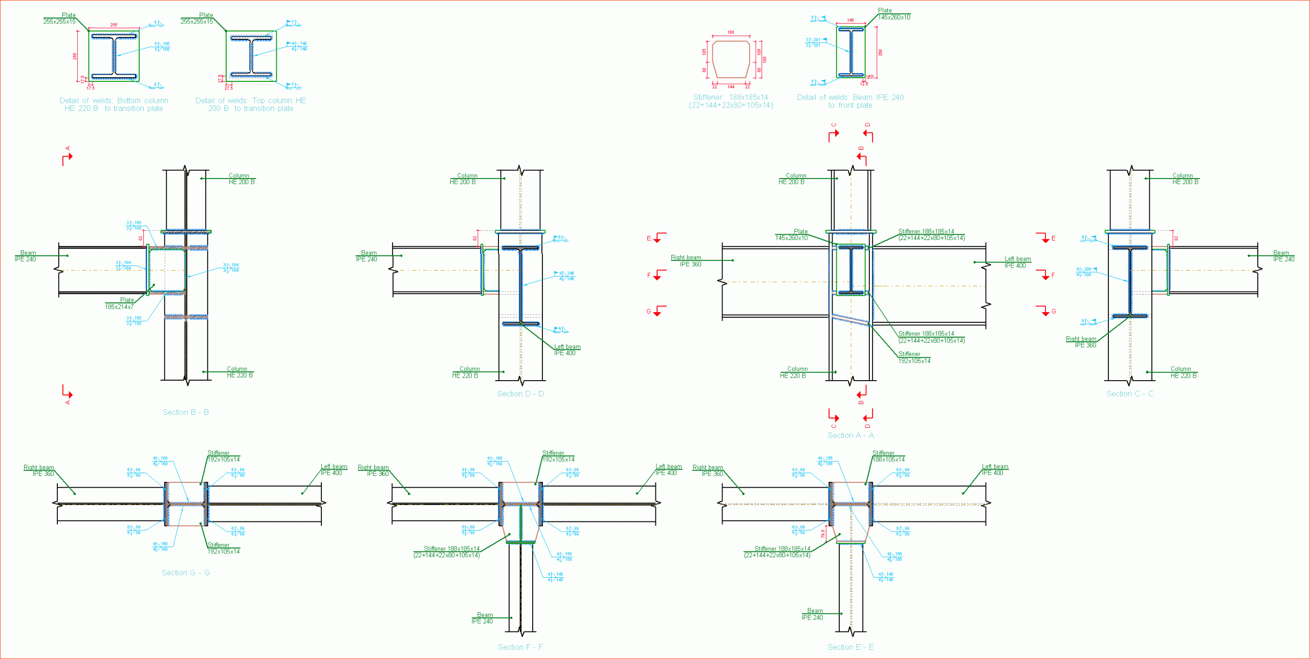
The new module Joints IV. Bolted. Building frames with rolled and welded steel I sections allows for the automatic design and analysis of the most common type of bolted connections of rolled and welded steel I sections in CYPECAD, its Integrated 3D structures and Metal 3D. More information can be found in the Bolted connections of rolled and welded steel I sections for building frames section (implemented codes, type of implemented connections…).

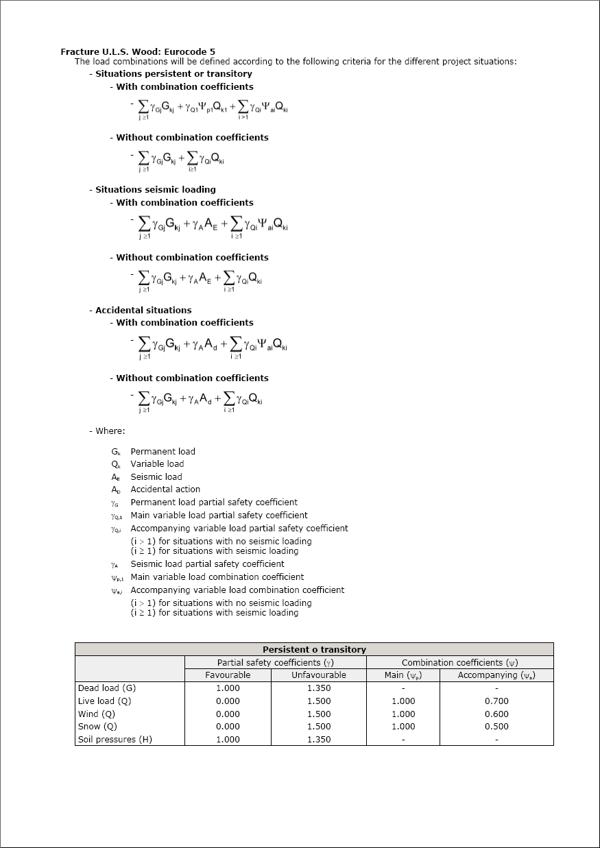
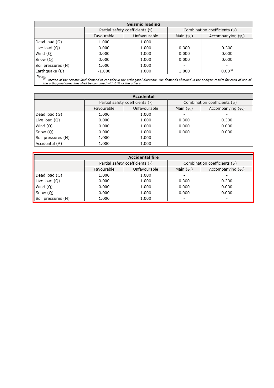
Generation of accidental fire combinations for wood
The automatic generation of accidental fire combinations for wood has been implemented according to the codes for wooden sections: CTE (Spain), Eurocode and NBR 7190 (Brazil).
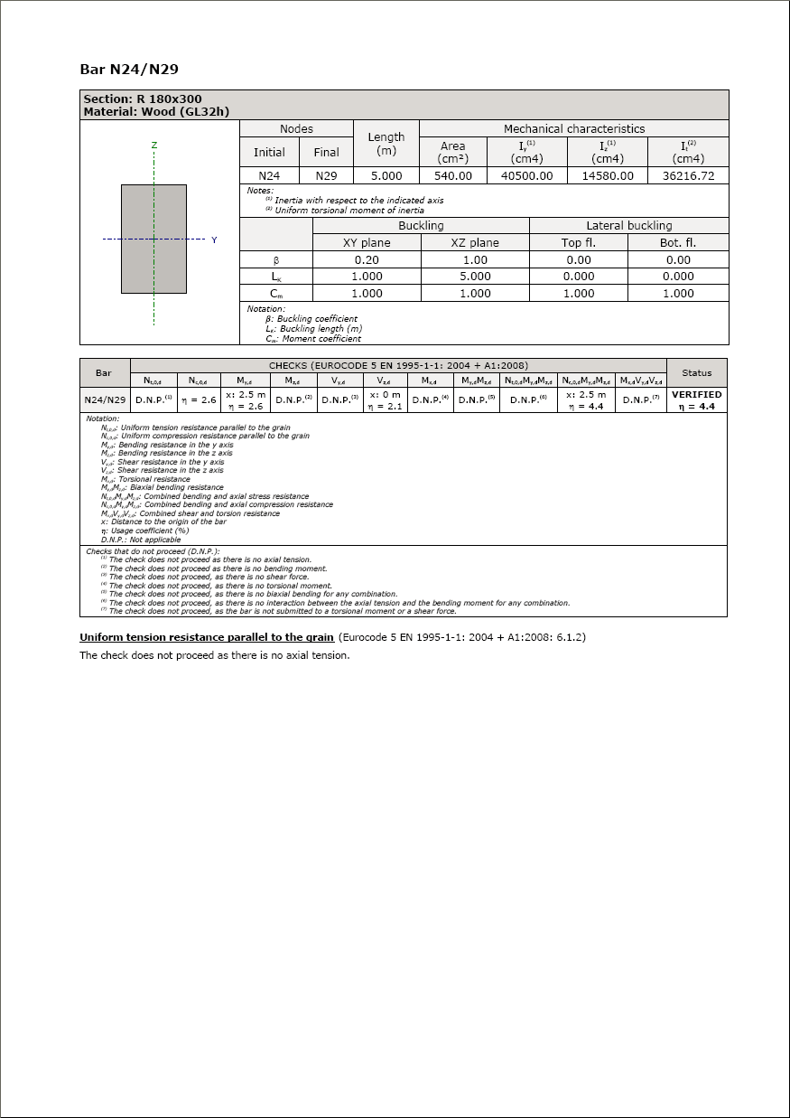
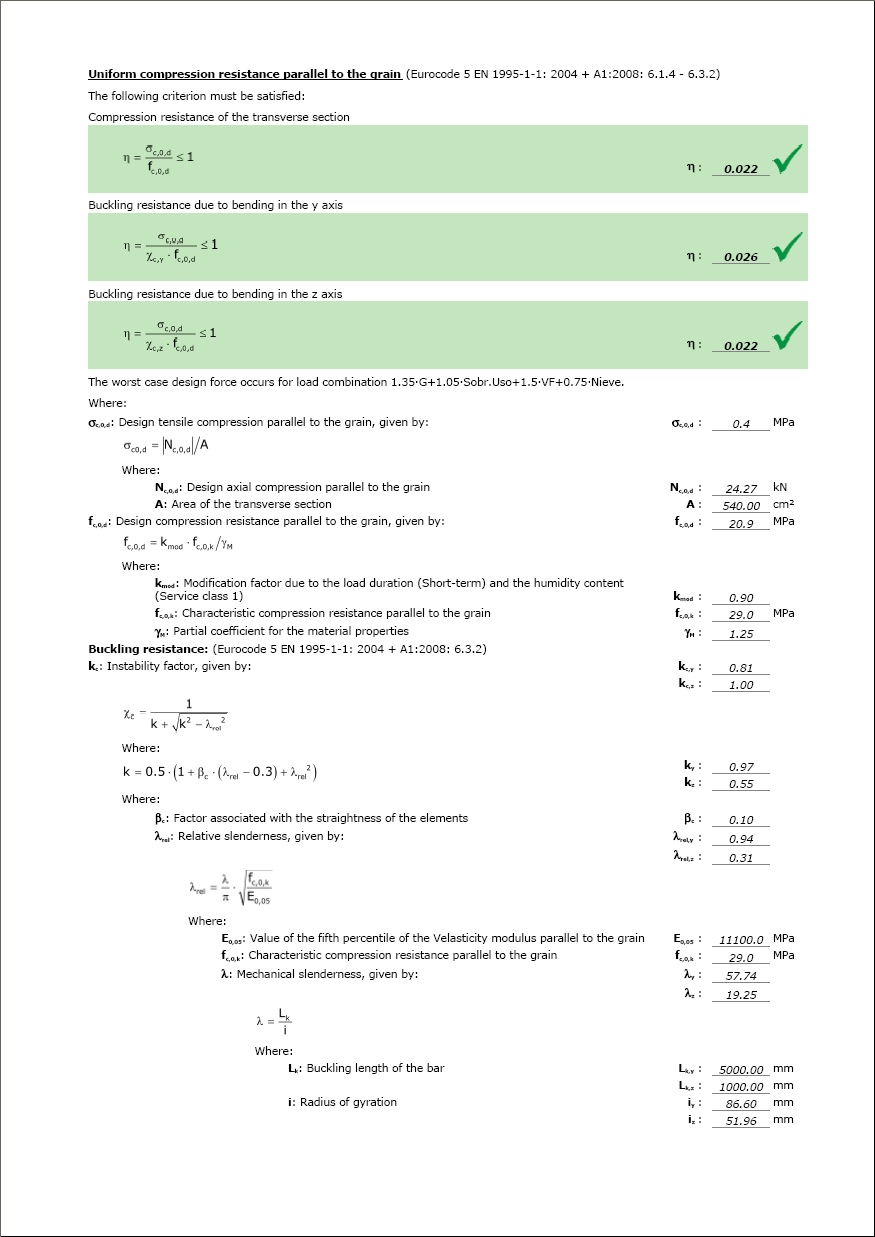
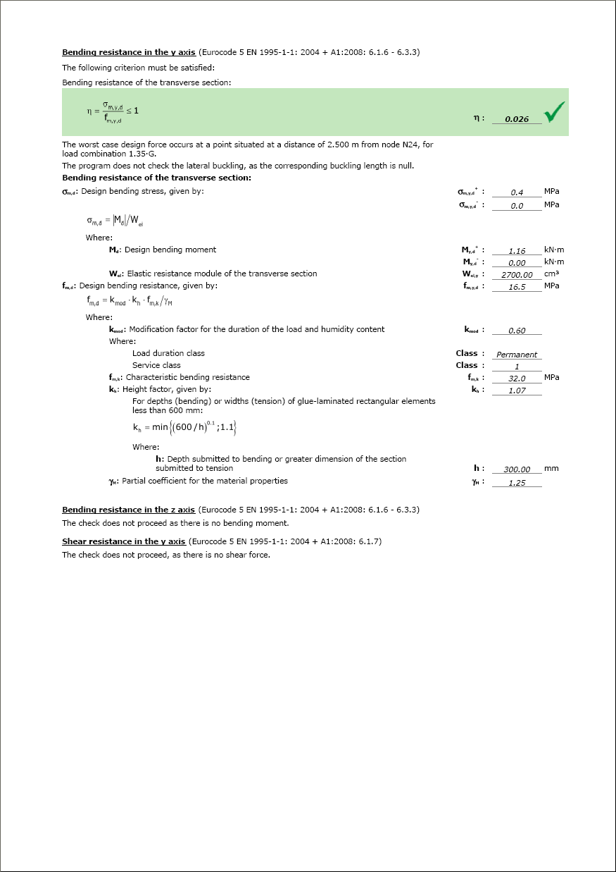
Ultimate limit state check reports for wooden sections
The ultimate limit state (ULS) check reports for wooden sections have been implemented for when analysing using the CTE. In this reports, a check is carried out on the resistance for outdoor temperatures situations and for fire situations (this last check if the user has activated the check for fire resistance).
Trimming of flanges and webs for pinned beam to column web connections
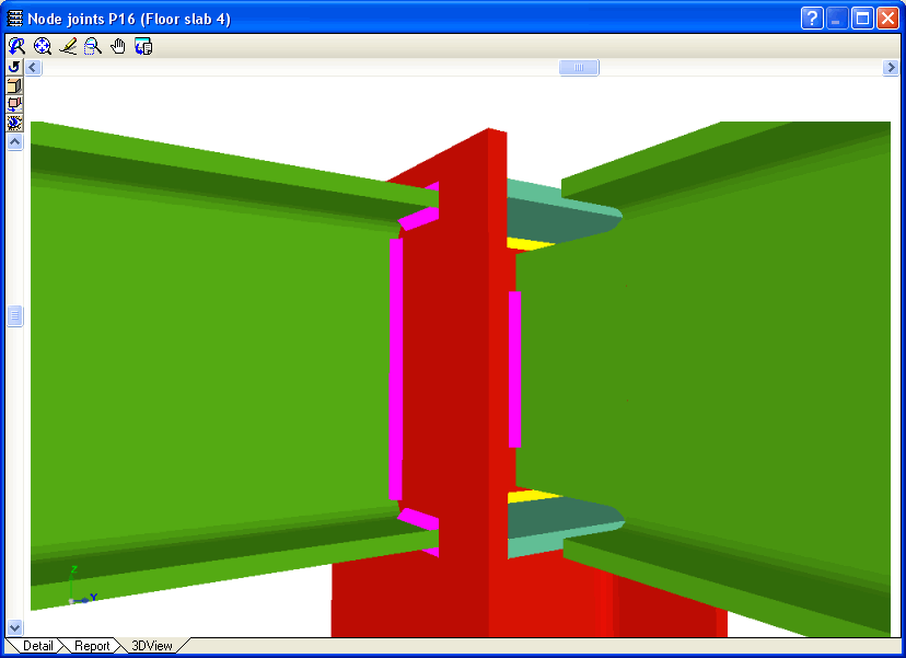
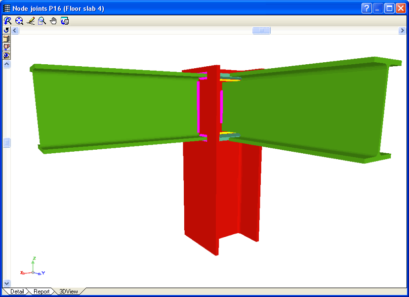
When beams pinned to the web of a column interfere with any stiffeners that are present due to beams fixed to the column flanges, the joint is designed in such a way by the Joints I. Welded. Warehouses with rolled and welded steel I sections and Joints II. Bolted. Warehouses with rolled and welded steel I sections modules that one of the flanges, both or even part of the web of the pinned beam is trimmed if necessary.
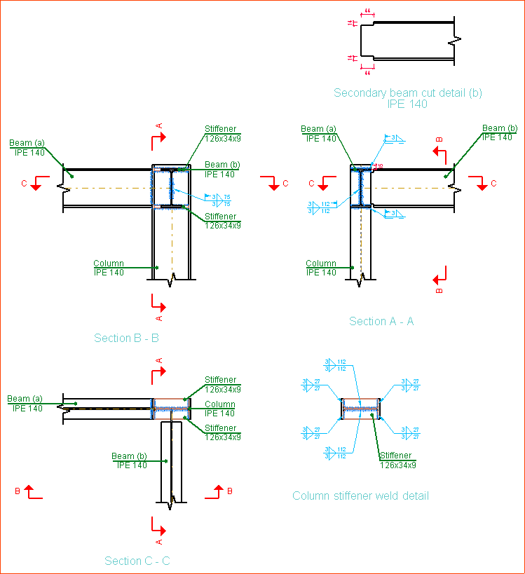
Joints III. Welded. Building frames with rolled and welded steel I sections (new module)
The new module: Joints III. Welded – Building frames with rolled and welded steel I sections allows CYPECAD, Metal 3D and the Integrated 3D structures of CYPECAD to carry out the automatic design of welded connections of common rolled and welded I steel sections in building frames.
More information on the properties of this module can be found in Welded joints for building frames with rolled and welded steel I sections (implement code, type of implemented connections…)