Update history​​

CYPE Architecture

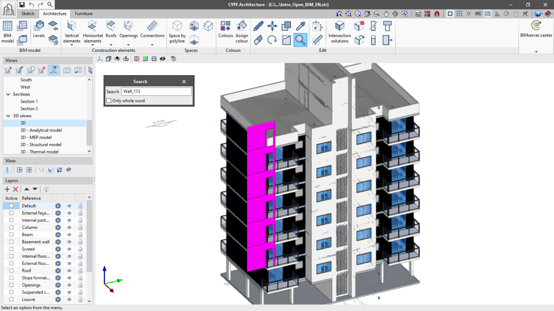
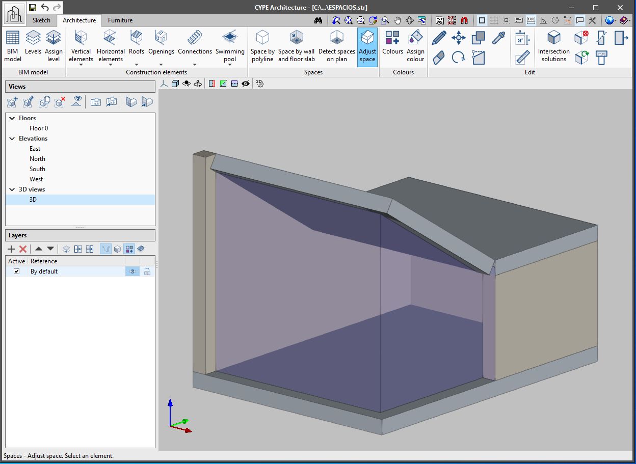
A new function, "Search by reference", has been implemented in the "Edit" group of the tool bar in the "Architecture" tab. This function allows searching elements by reference, thus easily identifying them. It is possible to locate only the references exactly as written (Only whole word) or all of the references that contain the text that is written.

The new "Show/hide information" function is found in the "View" section of the left-side panel of the program. If enabled, it allows the display of any element’s information when the cursor is placed above it.

In the panel, information related to reference can be seen, such as the level, type, layer and the properties of each element.

The "Tag" function in the "BIM Model" panel allows the organization of tags in groups. In this way element tags can be ordered appropriately (for example, according to applicable standards).

Additionally, the program allows local exporting and importing of groups of tags so that they can be used in other CYPE Architecture projects.

The program also includes a tag library for Spain. This library allows the importing of groups of tags created according to the Spanish code.

In the "BIM Model" group of the upper menu of the "Architecture" tab, the new "Architectural element types" function can be found. With this it's possible to create construction element types that can be later loaded during modelling, thus saving time introducing the job elements.

Project types can be created for each of the following elements:

  • Walls
  • Curtain walls
  • Louvres
  • Railings
  • Floor slabs
  • Columns
  • Beams
  • Suspended ceilings
  • Slope formation
  • Roof tiles
  • Ridges
  • Valleys
  • Windows
  • Doors
  • Skylights
  • Glazed surfaces
  • Stairs
  • Ramps
  • Landings
  • Curved ramps
  • Elevators
  • Spaces

The project types can be saved locally to be loaded later into another CYPE Architecture project.

The possibility of choosing a fixed height for louvres and curtain walls is included, which is especially useful when drawing them in floor view.

As of the 2021.e version, the height of the drain can be chosen in the slope formation.

A rotate button has been included in the Architecture tab. This rotation is carried out on the XZ axis of the workplane.

The introduction of walls and floor slabs is made easier. Now it is possible to view the plan where the wall and floor slab are being introduced.

The "Measure area" function in the "Edit" panel warns the user, by drawing the measurements in red, that it is not possible to measure the drawn area. The colour changes to pink when the measurement can be carried out correctly. It also allows users to dimension the perimeter of the surface being measured.

As of the 2021.e version, CYPE Architecture includes in the IFC file of the BIMserver.center project the following quantities sets for their corresponding IFC entities:

  • Stairs ("Qto_StairFlightBaseQuantities")

    • Length ("Length")
    • Gross volume ("GrossVolume")
    • Net volume ("NetVolume")

  • Ramps ("Qto_RampFlightBaseQuantities")
    • Length ("Length")
    • Width ("Width")
    • Gross area ("GrossArea")
    • Net area ("NetArea")
    • Gross volume ("GrossVolume")
    • Net volume ("NetVolume")

  • Beams ("Qto_BeamBaseQuantities")

    • Length ("Length")
    • Cross section area ("CrossSectionArea")
    • Outer surface area ("OuterSurfaceArea")
    • Gross surface area ("GrossSurfaceArea")
    • Net surface area ("NetSurfaceArea")
    • Gross volume ("GrossVolume")
    • Net volume ("NetVolume")

  • Barandillas ("Qto_RailingBaseQuantities")

    • Length ("Length")

These new quantities can be used in the Open BIM Quantities application to generate the bill of quantities of the architectural model.

In the "Openings" section of the architecture tab a "glazed surface" function has been implemented, which allows a glass surface that is not strictly square or circular to be constructed and then read in analysis programs. Two ways of creating glazed surfaces have been included: "By points" and "Per surface area".

  • By points
    Draw the desired surface on the wall or floor slab by clicking one by one on the screen the perimeter points that define it. If desired, a frame can be added to the glazed surface.
  • Per surface area
    Clicking on a sketch surface converts it into a glazed surface.

The "Spaces" section of the toolbar has been expanded and has new tools: "Space by wall and floor slab", "Detect spaces on plan" and "Adjust space". These new features provide greater agility when defining the spaces of the building.

  • Space by wall and floor slab

    Allows a space to be generated by selecting the surrounding walls and the lower slab that contains it. The steps to follow are:
  1. Click on the "Space by wall and floor slab" button.
  2. In the options panel that appears on the left side of the viewer choose the reference, label and level. Remember that it is important to fill in these fields so that the model can be correctly read in the rest of the Open BIM workflow programs.
  3. Choose the properties of the space that will be created: type (indoor or outdoor), height, colour and size of the space’s text label.
  4. Once all the options have been defined, choose all the walls surrounding the space and right click the mouse.
  5. Choose the floor slab that defines the bottom face of the space. The space will be automatically generated.
  • Detect spaces on plan

    Allows a space to be automatically generated when it is located in plan view. The steps to follow are:
  1. Go to a plan view and click on the "Detect spaces on plan" button. If this button is clicked whilst drawing in any other type of view (3D, elevation, section, etc), it will warn the user that this feature is only available for plan views.
  2. In the options panel that appears on the left of the viewer choose: the reference, label and level. Remember that it is important to fill in these fields so that the model can be correctly read in the rest of the Open BIM workflow programs.
  3. Choose the properties of the space that will be created: type (indoor or outdoor), height, colour and size of the space’s text label.
  4. Once all of the options have been defined, move the mouse cursor over the space to be generated. The spaces that are detected will be highlighted on the plan.
  5. Click on the space to be generated.
  • Space by polyline

    This feature already existed in previous versions of CYPE Architecture. To draw a space by polyline, indicate on screen, one by one, the perimeter points that make up the space.
  • Adjust space

    Allows the spaces of the roofs and sloped walls to be adjusted. This feature is automatic - click on the space to be adjusted and it will adapt to be contained between the surrounding walls and floor slabs.