As of version 2024.b, applications with the "Element selection tool" (this tool was implemented in version 2021.e) have the ability to move the selected model components with the arrow keys on the keyboard. The elements shall be moved on the work plane of the active view in the direction of the arrow key. Whenever the arrow is pressed, the distance that is displaced is constant, so zooming will make it larger or smaller.

Links to the BIMserver.center platform
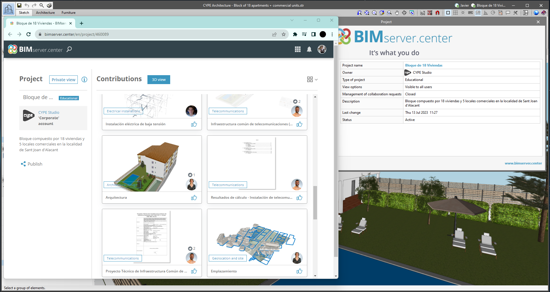
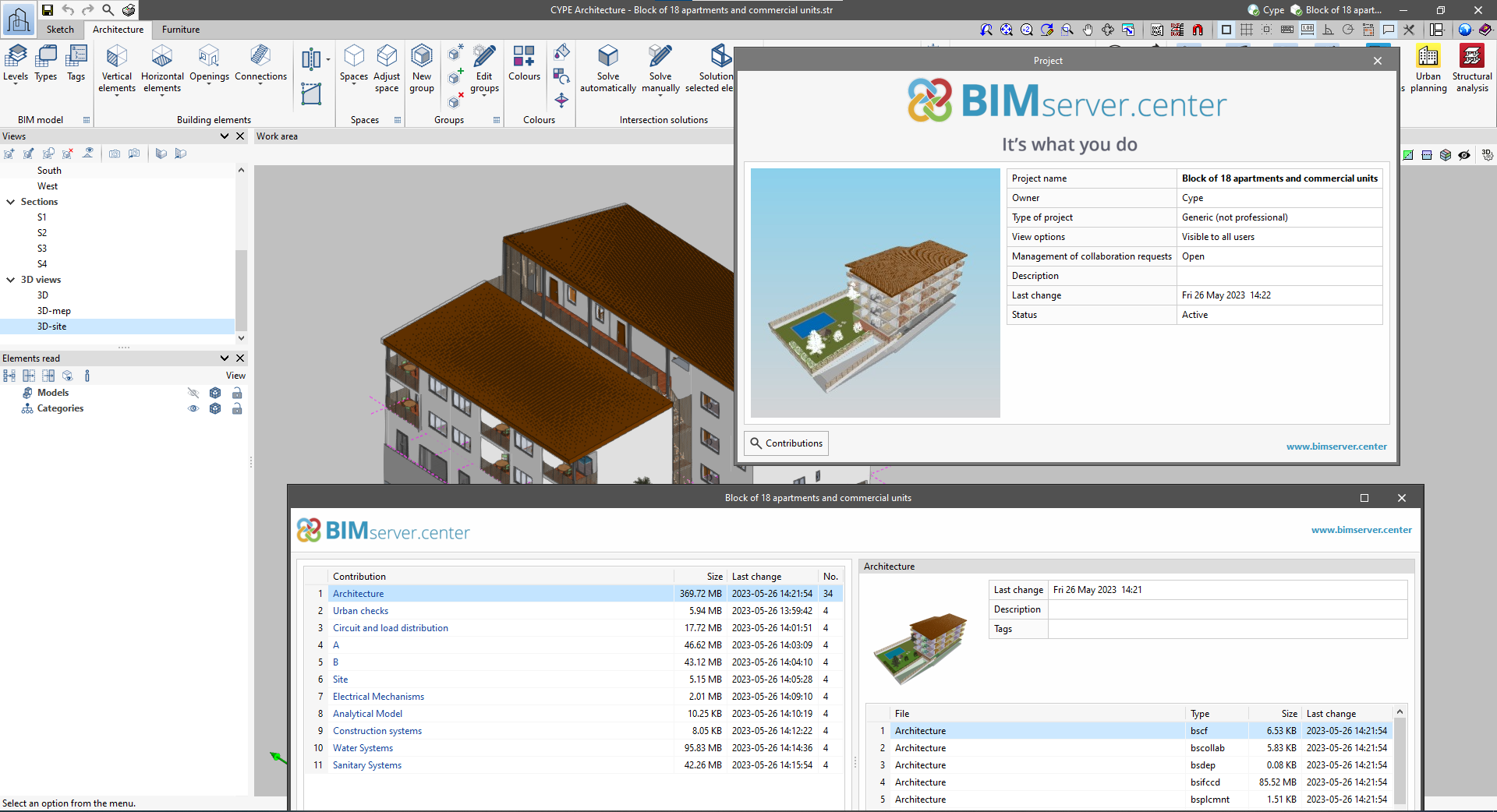
From the BIMserver.center project information window (displayed by clicking on the project name shown in the project information bar - upper right part of the application window) you can access the project page of the BIMserver.center platform via a link that has been inserted in the text indicating the project name.
Likewise, from the information window about the project contributions ("Contributions" option in the project information window), users can access the page of each contribution in the BIMserver.center platform. These links are inserted in the texts indicating the name of each contribution.
Notifications on the project status
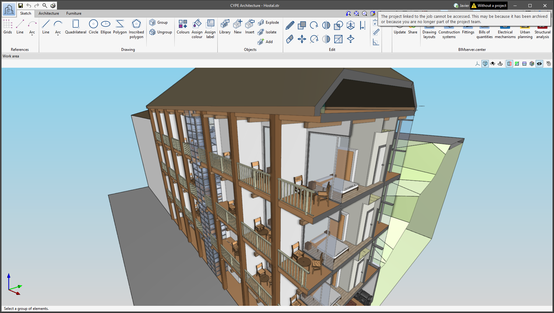
The status information bar of the BIMserver.center project is located at the top right of the window of the programs included in the Open BIM workflow. This bar has been available in the applications since version 2022.e and shows a warning icon when there is a problem with the connection to the project, as well as other things. Now, in version 2024.b, users can obtain more information about the warning by hovering the mouse cursor over the icon.
Creating BIMserver.center Corporate projects
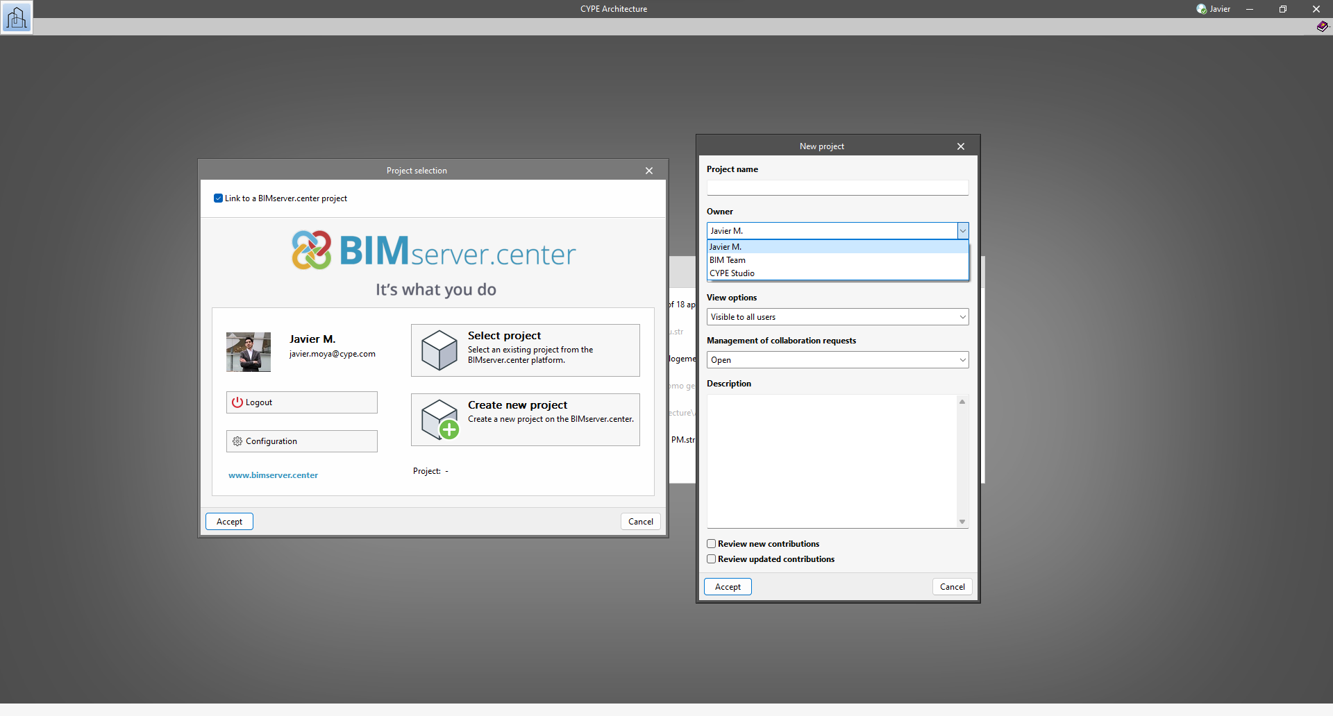
As of version 2024.b, users can create projects associated with a "BIMserver.center Corporate" account from all CYPE applications included in the Open BIM workflow. To do this, the "Owner" field has been added to the window for creating a new project. This is a drop-down menu that includes, as one of the available options, the logged-in BIMserver.center user name along with the "BIMserver.center Corporate" accounts to which it has access. When selecting the user name as the owner, the project will be associated with this personal account, as was the case in previous versions. On the other hand, if a BIMserver.center Corporate account is selected, the project will be associated with that account.
Clear cache
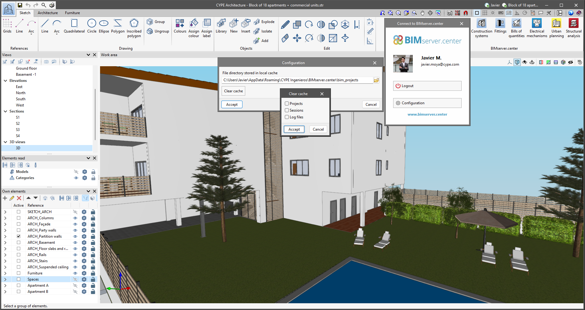
The "Clear cache" button has been added to the CYPE applications included in the Open BIM workflow in the "Configuration" dialogue box that opens with the following sequence of commands: Select any of the options in the "BIMserver.center" tool group > "Configuration" option in the dialogue box that appears. When clicking on "Clear cache", the following options are displayed:
- Projects
Deletes projects, contributions and documents downloaded from the platform that are in the "File directory stored in local cache". - Sessions
Deletes the data of any active sessions. This action will require applications to be re-authorised to access BIMserver.center. - Log files
Deletes transaction logging from applications with BIMserver.center.
New example job
In version 2024.a of CYPE Architecture, the "Town houses" example job has been included. This is a residential development consisting of 12 two-storey houses with a private garden. The building also has commercial units, a garden, a swimming pool, a gym and an underground car park for 14 vehicles.

New method for connecting applications to the BIMserver.center platform
The mode of communication between Open BIM applications and the BIMserver.center collaborative work platform has changed. In previous versions, the applications used the "BIMserver.center Sync" tool to upload and download the files of the contributions associated with the project from the platform. This tool was downloaded from the BIMserver.center platform or installed together with the installation of the platform applications if users so desired.
From version 2024.a onwards, applications are now able to work directly with BIMserver.center without an intermediary. That is, without the need for the "BIMserver.center Sync" tool.
This modification will improve the performance and efficiency of Open BIM applications significantly. By removing this dependency, the applications have more autonomy and the waiting times for communication between BIMserver.center Sync and the program have been considerably reduced. The process of downloading contributions has also been optimised, as users no longer need to obtain the entire content of a project from BIMserver.center in order to work, but only the contributions to be read.
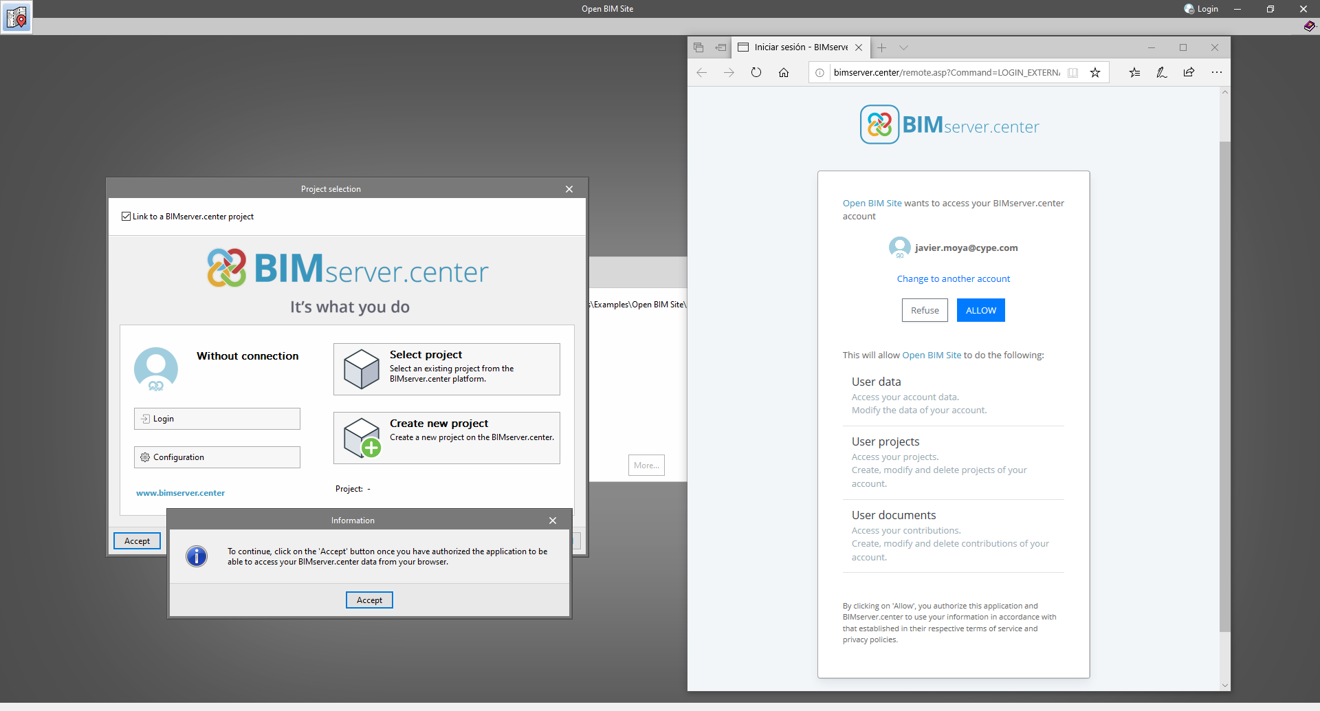
The way of authenticating a BIMserver.center user in the applications has also been modified. Now, this process is carried out within the BIMserver.center web platform. To do this, the application with which the user is working will run the user's default browser when the "Login" button is pressed. When the credentials are entered, or after opening the browser if the user is already connected to the platform, an authorisation page will be displayed. This page details the resources the application is requesting access to and two buttons for granting or denying this access.
The authorisation must be carried out for each application. Once access has been granted, it is saved for the next time the program is run and there is no need to perform this process again for that application.
As well as performance improvements, changes have been made to the user interface of the Open BIM applications regarding the connection to BIMserver.center.
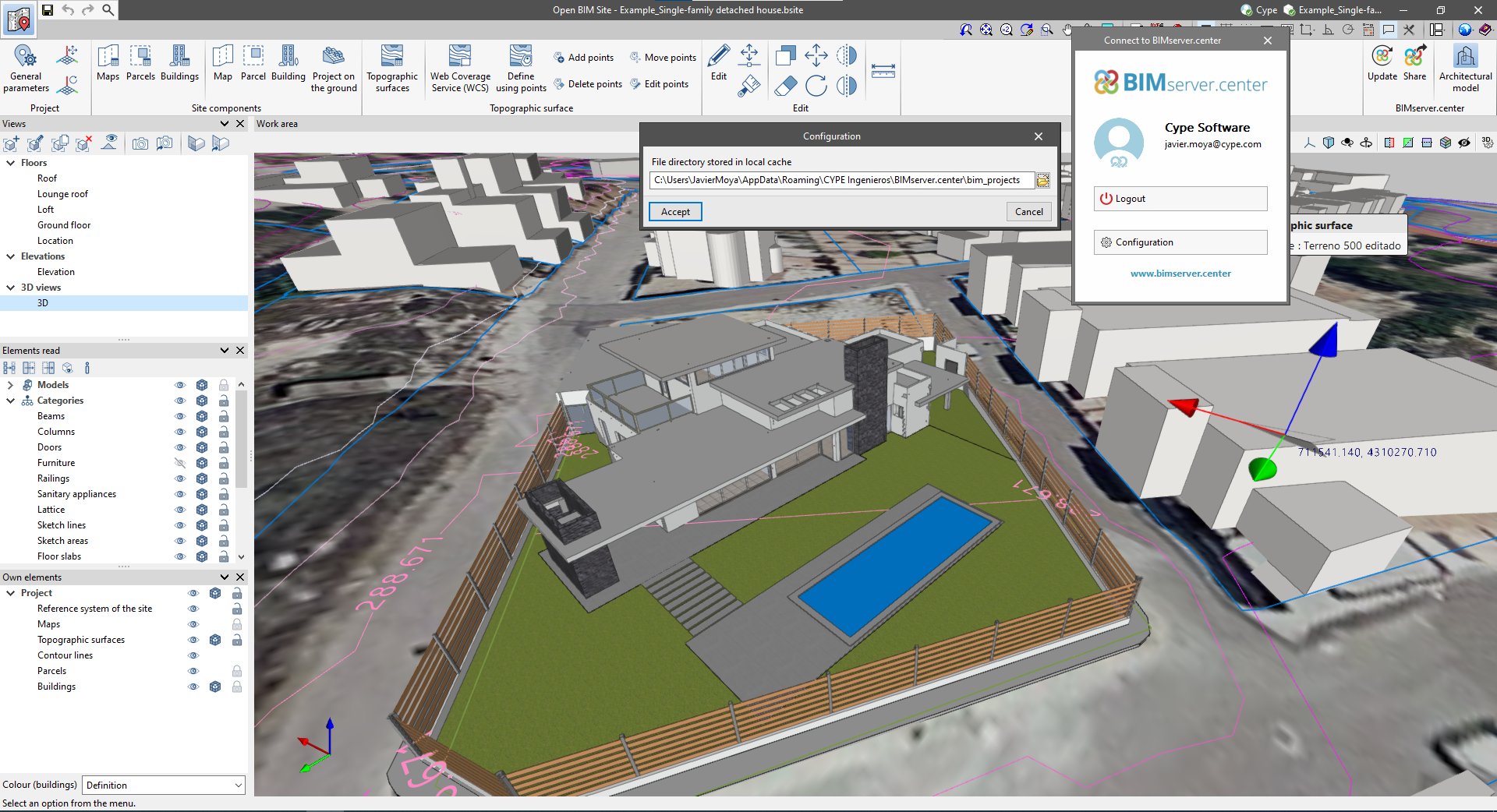
- The "Connect to BIMserver.center" window now includes a "Configuration" button. Clicking it launches a menu from which you can edit the "File directory stored in local cache". This is the path where the files that make up the contributions will be downloaded when working with them from the applications. In previous versions, this location could be selected from the BIMserver.center Sync tool.
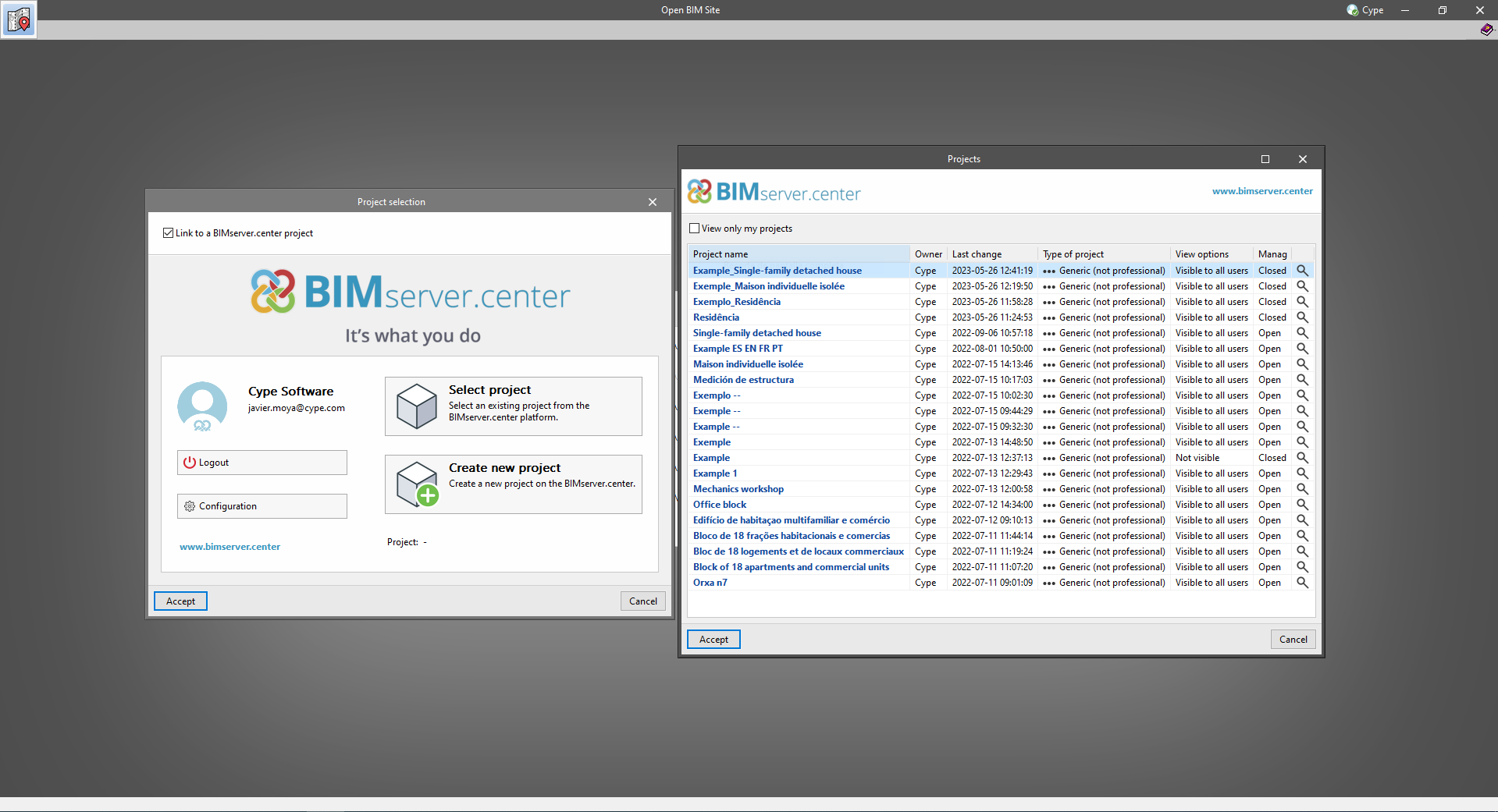
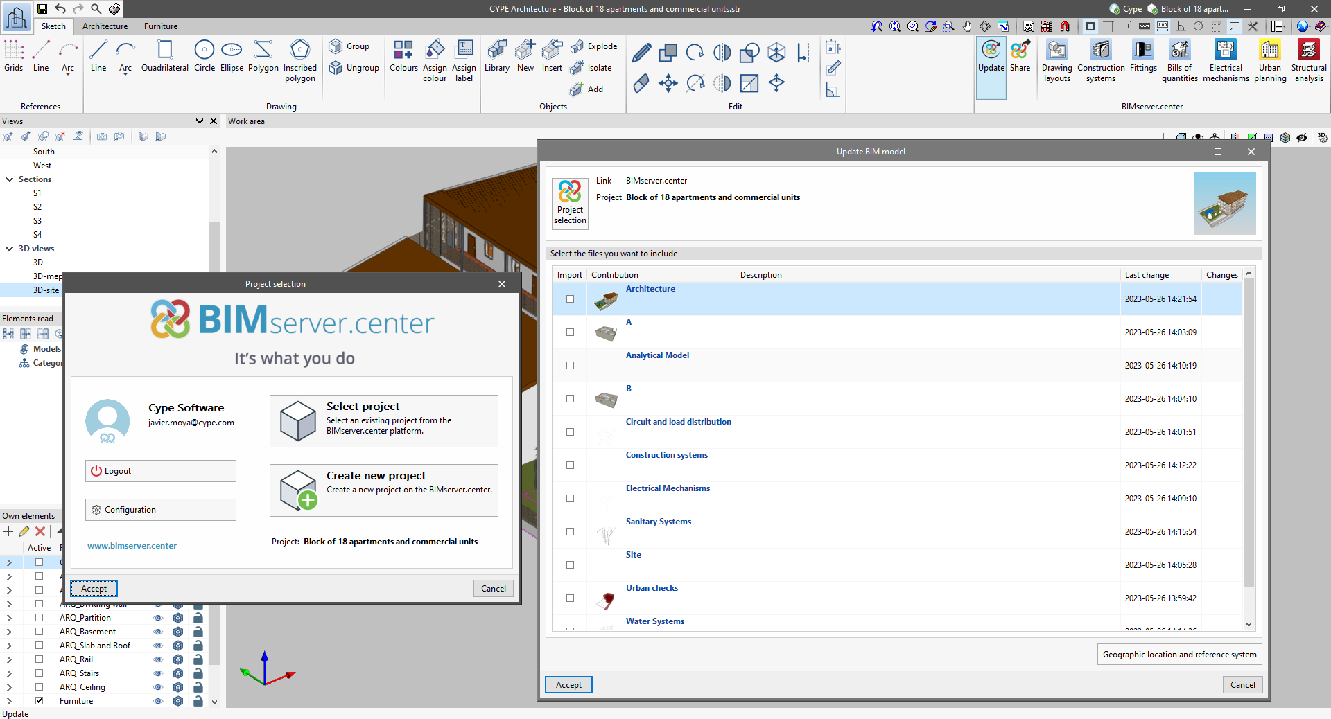
- The appearance of the "Project selection" window has been modified.
- In the "Select project" list, the "View only my projects" option has been added to show only the projects where the connected BIMserver.center user is the owner. Icons have also been included for the "Type of project" column in order to make it easier to identify them. The detailed data of a project now shows the image of each contribution, the description and the tags.
- The "Review new contributions" and "Review updated contributions" options have been added to the "Create new project" window.
- The list for selecting contributions ("Import BIM models") now includes the images of the contributions and the tags. The name of the contribution will be displayed in blue to indicate that the owner is the logged-in user.
- When sharing a contribution or selecting contributions during the process of linking to a BIMserver.center project, a progress window will appear during the upload or download process.
To work in BIMserver.center with versions of Open BIM applications prior to 2024.a, users must continue to use the BIMserver.center Sync tool. This is still available for download from the platform and was included in the installation packages of the CYPE Open BIM applications prior to 2024.a.