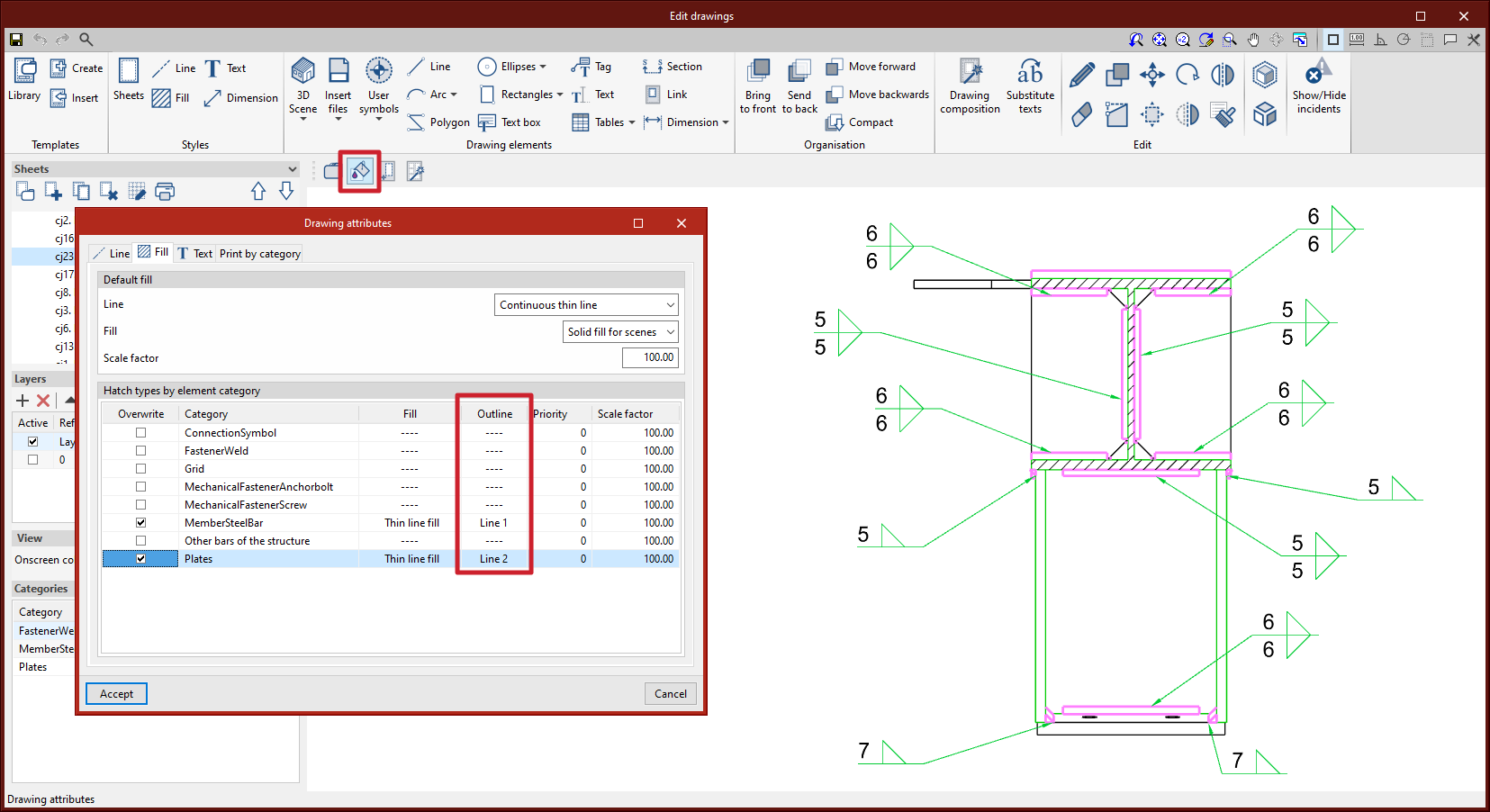
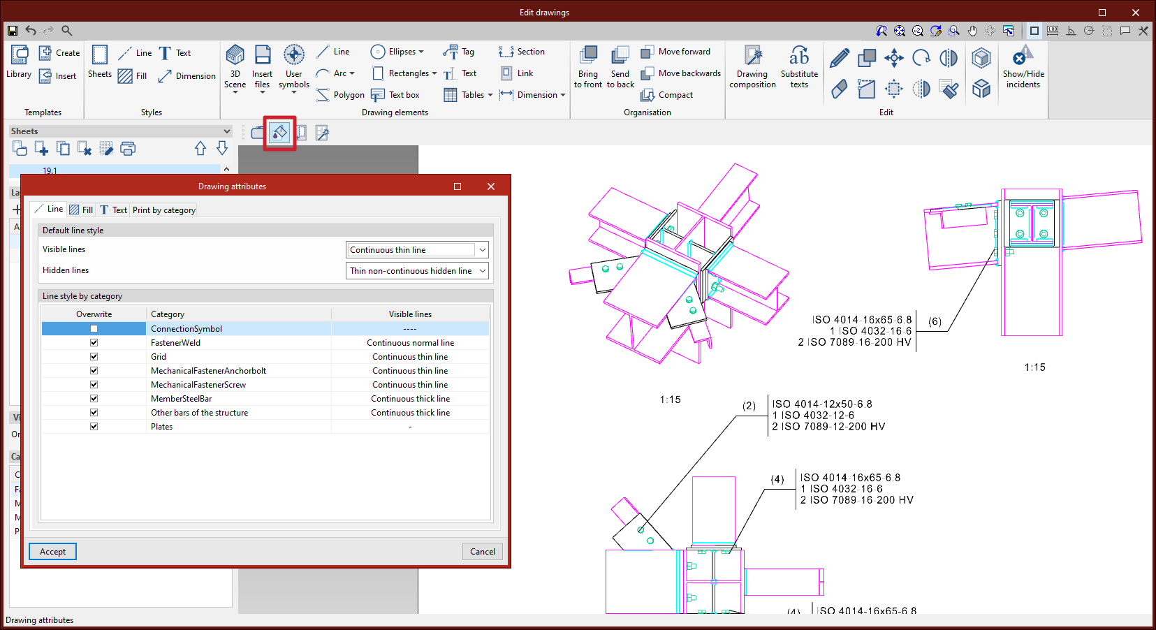
In version 2023.d, the editing of the line style for the outline of section fills in scene views has been added. From "3D Scene" > "Drawing attributes" > "Fill", users can access the dialogue box that allows them to edit the line style by category.

In version 2023.d, the editing of the line style for the outline of section fills in scene views has been added. From "3D Scene" > "Drawing attributes" > "Fill", users can access the dialogue box that allows them to edit the line style by category.
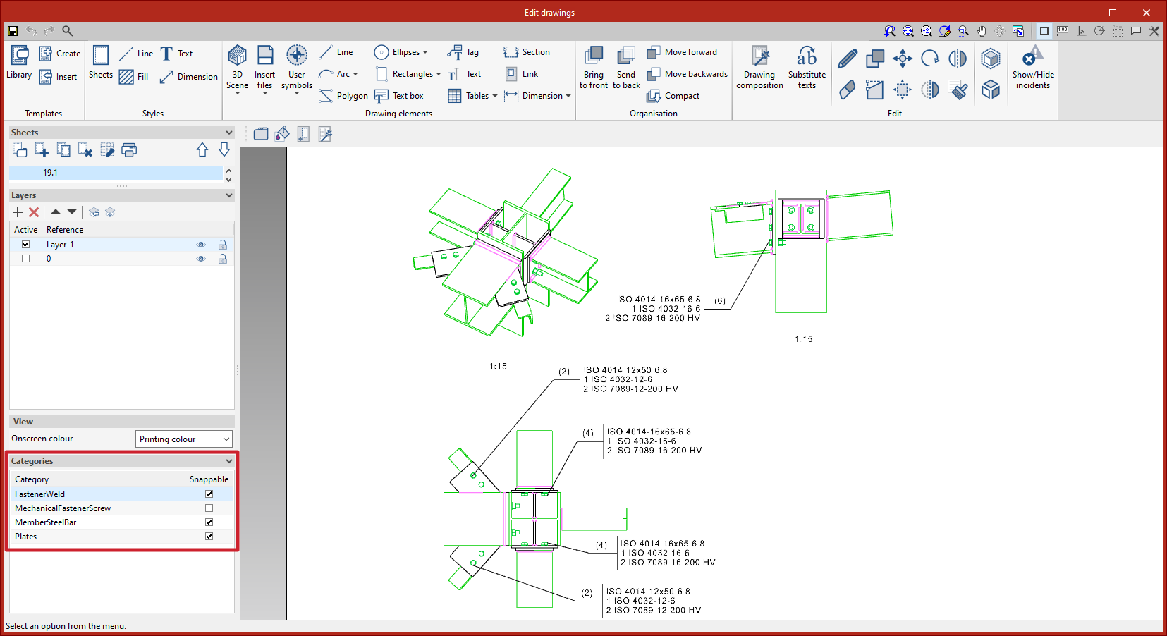
In version 2023.d, the management of categories marked as "Snappable" has been added to the sidebar. Each element in the 3D scenes belongs to a category.
This improvement is useful, for example, when tagging or dimensioning items to deactivate categories that don't need to be snapped. The sidebar location allows quick access to this commonly used tool.
In version 2023.d, the print management of elements according to their category has been added. From "3D Scene" > "Drawing attributes", users can access the dialogue box that allows them to select the categories to be printed ("Print by category" tab). Unchecked categories will be displayed on screen but will not be printed. This implementation is particularly relevant, for example, with connection symbols, which should be displayed on screen so they can be tagged, but not printed (see new feature "Connection symbols in drawing layouts").

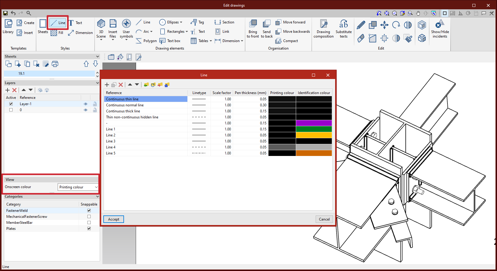
Line style editing by category has been added. The dialogue box for editing the line style can be accessed from the "3D Scene" tool > "Drawing attributes" option. When the scenes are defined as a vector image, the edges of the elements can be seen on screen according to the line style and the colour chosen by the user between the identification colour or the printing colour.
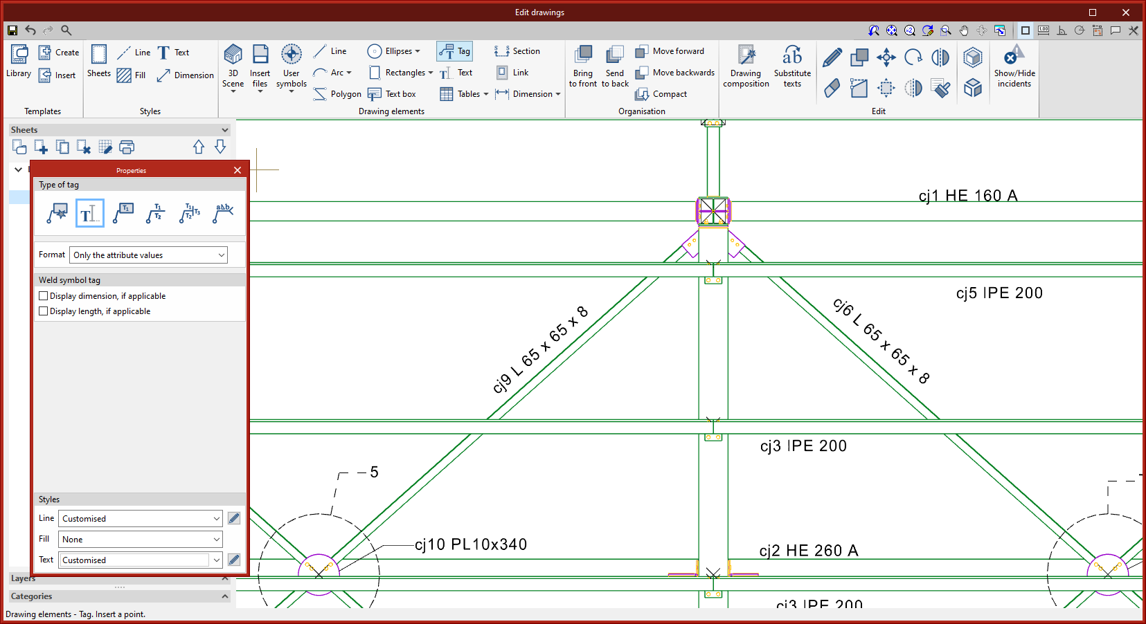
A new type of tag has been added where only text is displayed. This tag is particularly relevant to StruBIM Steel model views and assembly drawings, where the automatic tag is generated for the bars, aligned to their axis.
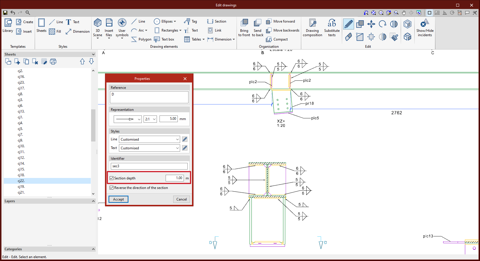
Up until version 2023.d, section depth could not be edited. Therefore, the scene was displayed from the position of the section line to the end.
As of version 2023.d, the depth can be edited. This way, parts of the scene that are not relevant to the section drawing can be omitted.
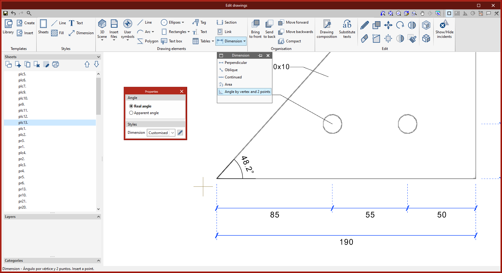
The dimensioning tool "Angle by vertex and 2 points" has been implemented. This tool allows angles to be dimensioned using 3 points. First, the angle's vertex must be selected, followed by a point on each side.
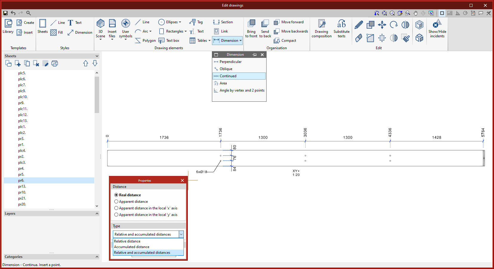
A new dimensioning tool has been added. This tool allows more than one section to be continuously dimensioned. This type of dimensioning allows the "Relative distance", the "Accumulated distance" or the "Relative and accumulated distances" to be displayed.
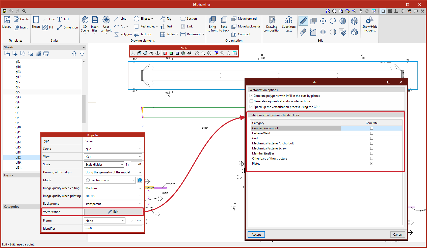
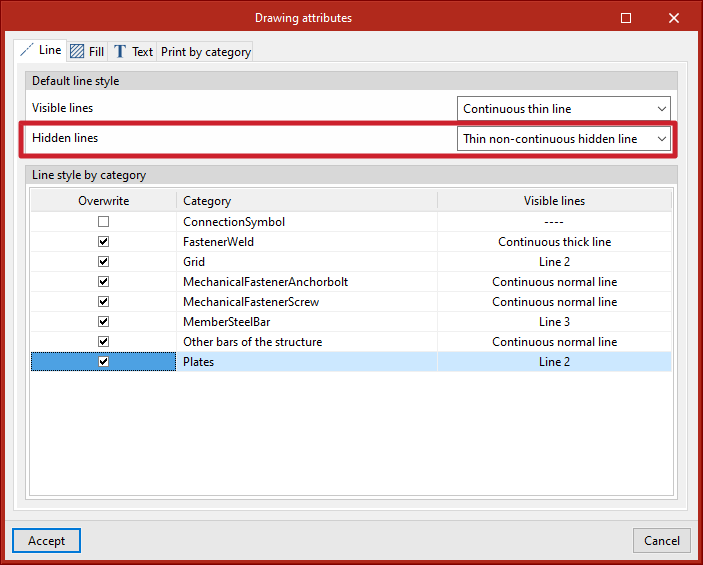
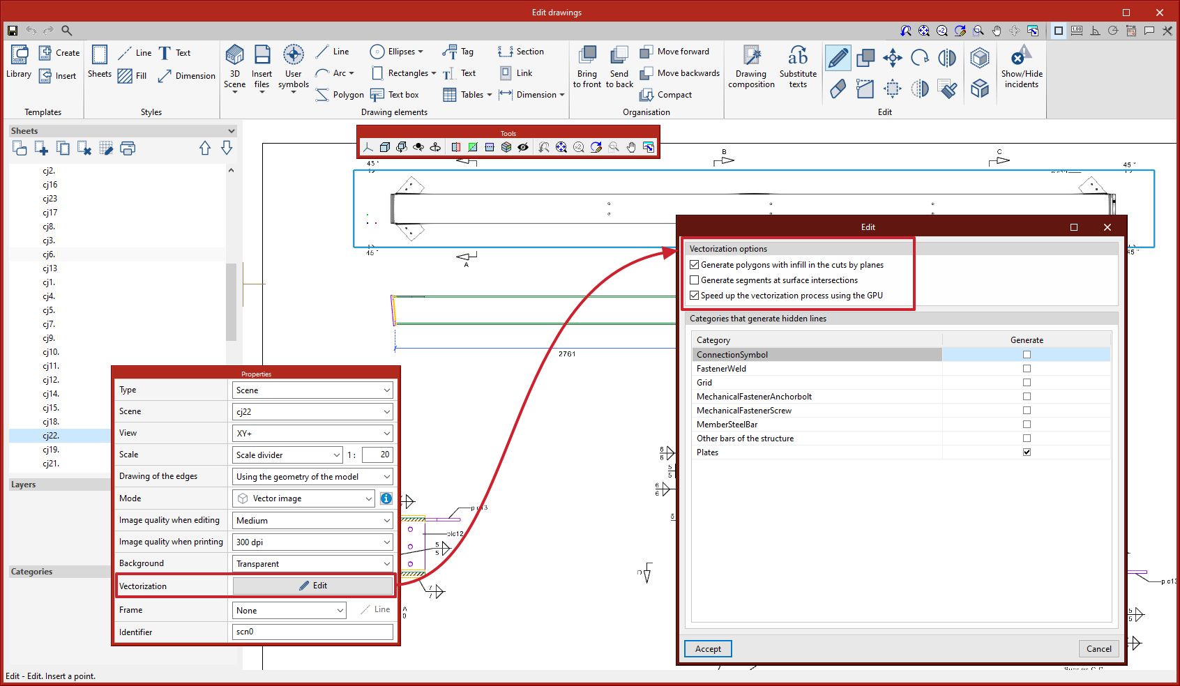
Hidden lines can now be drawn in scenes. Users can select the categories of elements that generate hidden lines in each scene from the editing panel of the "Vectorization" option.
The dialogue box for editing the drawing style of the hidden lines can be accessed from the "3D Scene" tool > "Drawing attributes" option.
In previous versions, the Open BIM Layout, StruBIM Steel and CYPE Connect programs had the following scene drawing modes: "Normal image" and "Monochrome image". As of version 2023.d, two additional modes have been added:
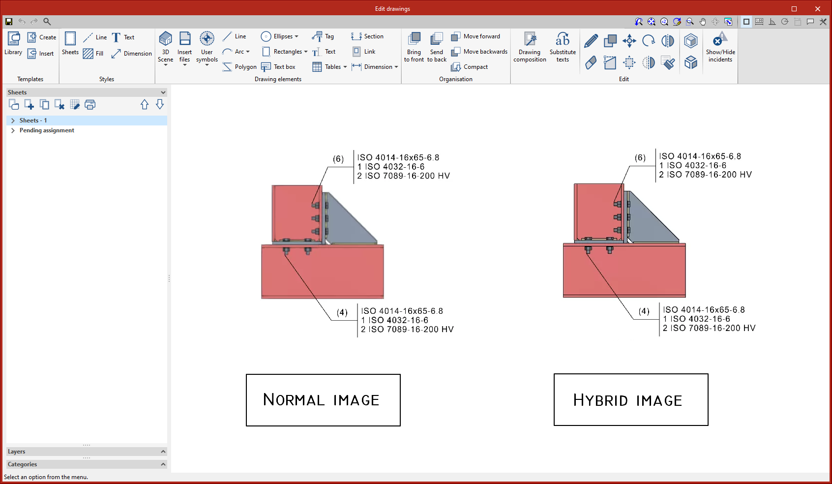

The type of image can be selected from the editing panel in each scene.

The following options can also be accessed from "Vectorization":
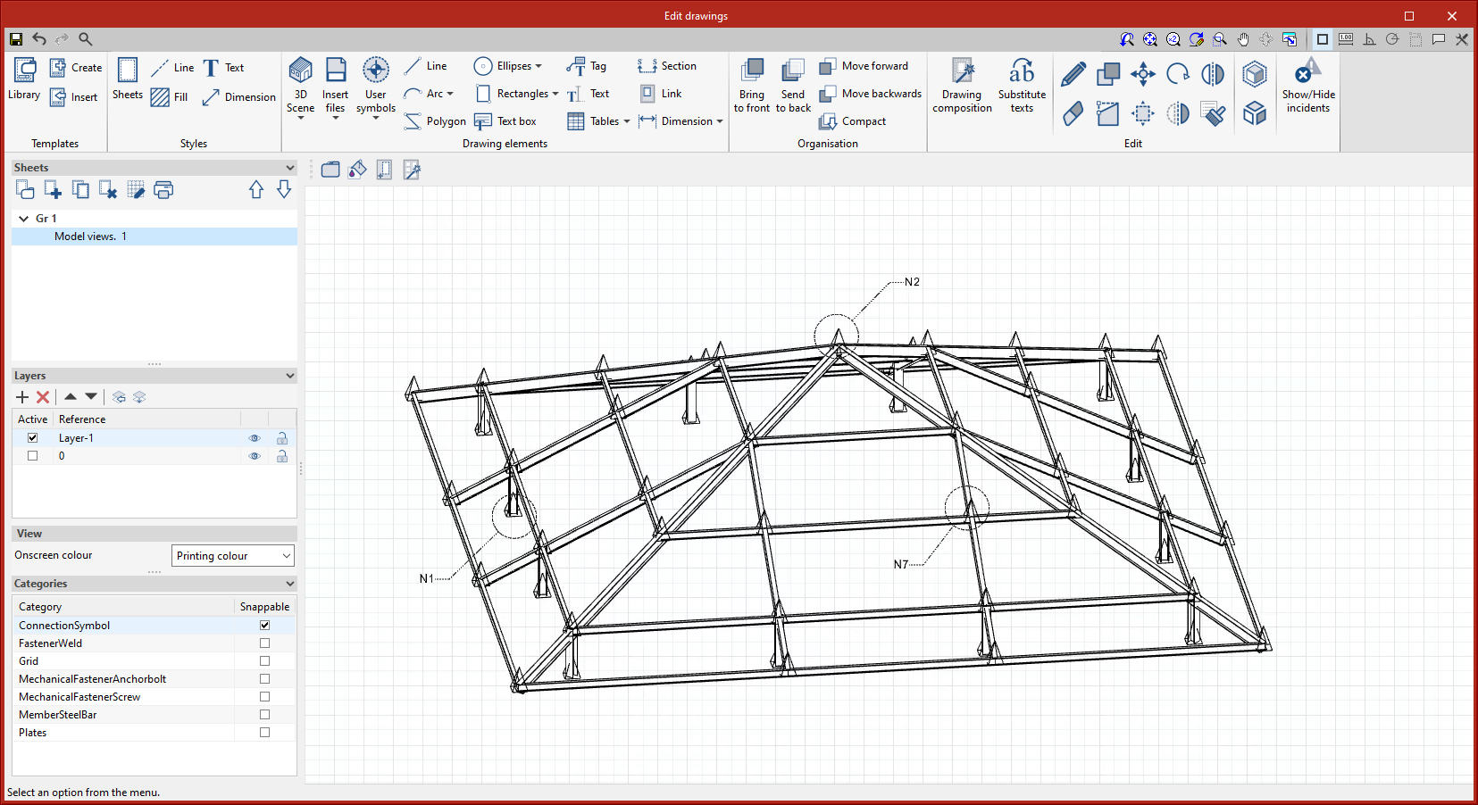
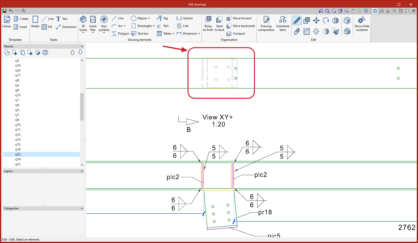
In version 2023.d, connection symbols are included in the "Drawing composition" in order to label the connections in the views of the structure. The connection symbol can be snapped with the "Tag" tool. The automatic tag will display the connection reference. The connection symbols will not be printed by default, however, users can manage this printing (see the new feature "Print management by categories of elements").