Update history​​

CYPECAD

The 2021.c version of CYPECAD also includes other small improvements and correction of issues that could occur in unique cases:

  • When a beam is inserted or extended, it is possible to snap to any point at the end of a wall. Until the 2021.c version, it was only possible to snap to the axis of the wall.
  • It is possible to copy the elements that have been entered, from one group to another, using editing resources with the "Copy elements to another group" option.
  • When a castellated beam is defined, the depth and other dimensions of the section are displayed. The depth is also shown in "Beams - Information".
  • By pressing the "Drawings" button, information is generated for all the possible drawings. This is generally quite fast except in some "Column schedule" and "Column details" drawings. As of the 2021.c version, it is possible to cancel the process to obtain this information if the corresponding drawings are not going to be generated.
  • The "Centre of mass and centre of stiffness" selection of "Visible references" remains after the program is closed.
  • Upon changing the initial or final group of a column, users can edit the fixity and buckling coefficients at the new floors.
  • A new check for panel outline intersections is included. This check is done before the project is analysed to avoid later errors.
  • This situation has been found to occur in some cases when beams with very different widths meet.
  • The forces at column starts which are shown in the "Column starts, shear walls and walls by loadcase" chapter take into account the elements that are connected to the start, in the same way as those shown in the "Foundation loads" drawing.
  • During the update process of the BIM model, the templates of the columns are updated.
  • The export process of the deformed shape to the BIM model has been improved, whereby its incorrect positioning in certain occasions, has been corrected.
  • The detection of concrete columns during the import of IFC files has been improved. Previously, in certain cases, no columns were detected.
  • An error that occurred when selecting "Strap and tie beams > Match" in a project that had not been analysed has been solved.
  • An error has been solved that caused that, after editing column starts, the length of the starts was not shown in the "Column schedule" drawing in certain circumstances.
  • An error that occurred in some cases when "Import series of drawings" was selected in a project that had not been analysed has been solved.
  • A wall data inconsistency error has been solved, which could occur when a floor was added over another in which walls had previously been inserted on other walls.
  • An error that occurred when consulting forces for combinations in timber or composite columns has been solved.

Users can choose the colours with which the elements of the project are exported in two different ways:

  • According to its material
    Elements of different types but with the same material are shown with the same colour. For example, a concrete column and a concrete beam have the same colour.

  • 3D view of CYPECAD
    Each item will have the same colour as in the 3D view.

As of the 2021.c version, the "New floors" option allows for floors to be added below the current foundation group.

In the previous version (2021.b) the possibility to customise reports in CYPECAD based on predefined reports was implemented.

Now, in the 2021.c version, the following predefined reports have been added to optionally include them as chapters in the customisable reports:

  • Beam reinforcement report
  • Beam takeoff
  • Job takeoffs
  • Reinforcement quantities, per diameter

If any of these chapters is selected, it is possible to configure the data to be listed using the "Report options" button.

Structural use of concrete. Part 1: Code of practice for design and construction.

Implemented in:

  • CYPECAD
  • CYPE 3D
  • Shear walls
  • Reinforced concrete cantilever walls
  • Foundation elements

The 2021.b version of CYPECAD includes other improvements and program corrections that may be required in unique cases:

  • The "Characteristics that have been considered for the soil-structure interaction" have been improved. Now, all the information is contained in a single table.
  • The soil-structure interaction can be edited when editing footings and pile caps.
  • Object snaps no longer have to be activated in the Frame reinforcement editor to consult checks.
  • A waffle slab reinforcement error has been corrected. On some occasions, the end of the anchorage of the second layer reinforcement was straight when it should have been curved.
  • The "Tags" option is added to the "Results" tab. Until now, it was only available in "Beam Definition".
  • The size of the “Block frame reinforcement” dialogue box can be adjusted.
  • In the "Column schedule" drawing, the text of the floor size is not limited.
  • "Assign wall foundations" is included in the "Foundation" > "Foundation elements" option in the "Results" tab.
  • A specific error that occurred when structures with connections were exported to an IFC file has been corrected.
  • Specific errors that arose when consulting contour maps, causing a general error in the program, have been corrected.
  • A warning is displayed if the top of a wall is defined with several sloped planes. Previously, this case produced a general error in the analysis process.
  • Some of the thickness values of anchorage plates, which were displayed rounded, are now displayed with greater precision in drawings.
  • The criteria to determine the depth of beams that are embedded in walls and crown beams has been modified. If the beam is in contact with a floor slab, its depth will be taken as the largest value between the depth of the floor slab and the value defined in the options. Otherwise, it will be taken as the greater value between the wall thickness and the value defined in the options, with a maximum limit of one metre.

As of the 2021.b version, users can customise CYPECAD reports.

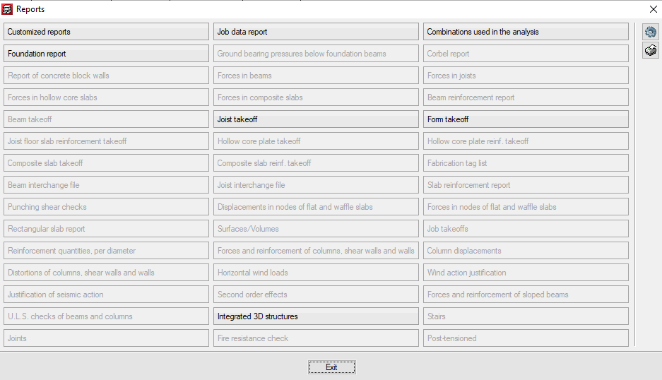
The "Customised reports" option allows users to select the reports that are to be generated. These reports must have been defined previously using the "Available customised reports" button.

These reports can be used in any project and can be used on another computer on which the 2021.b or later version is installed.

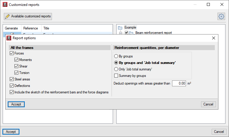
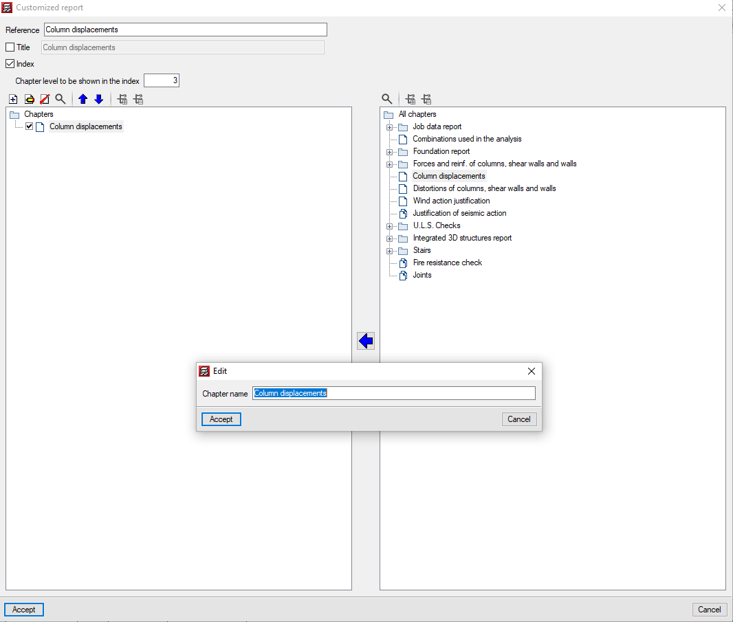
For customised reports, users can define their chapters as well as the title of the reports and whether their index and chapter levels are to appear.

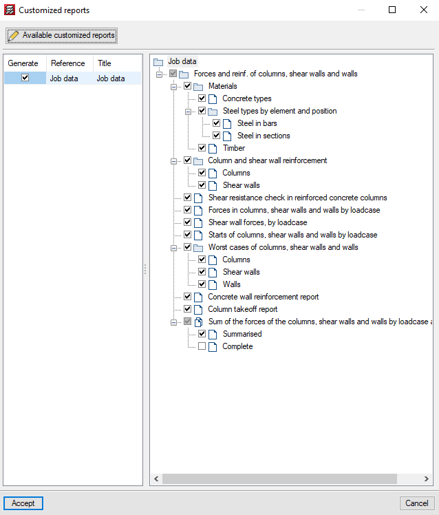
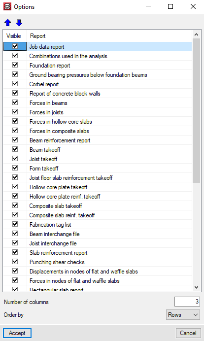
The chapters that make up the report must be selected based on the chapters of the predefined reports that appear in the tree on the right. They can be grouped and organised as users wish. The name of the chapters can be modified, and users can add empty chapters to include the information later on.

For the time being, the chapters of 13 predefined reports can be used, but we continue to work to implement as many predefined reports as possible.

In the 2021.b version, the "Reports" dialogue of the "File" menu can be configured by users. The appearance of the panel that is displayed when "Reports" is pressed has changed. It shows all the reports that are available in the program. The buttons that correspond to reports that cannot be displayed in the current project are disabled.

The "Options" button allows users to select which reports appear in the panel and the order in which they are displayed. This way, users can only show the reports that they usually use in the panel organised in accordance to their preference criteria.

The 2021.a version of CYPECAD also includes other minor improvements and corrections of the program that can arise in specific cases:

  • Possibility to add the options “Enter double joist”, “Check the geometry of the current group”, “Check geometry of current group and higher groups” and “Check the geometry of all groups” in the toolbar.
  • Corrections in the generation of the 3D views of floor slabs.
  • Corrections in the 3D view of beam intersections.
  • Detection of construction elements that have been defined incorrectly.
  • Corrections in the reinforcement detailing of concrete columns with generic sections.
  • Corrections in the consultation of force combinations for timber columns.

A warning is displayed in the final design report if, during the design process of floor slabs, waffle slabs or drop panels, the base reinforcement has been modified in any way. The slabs on which any changes have been carried out are indicated.

The options that are selected in “Template object snaps” are saved when the Accept button is pressed. This way the selection remains for when the program is executed in the future.

In the 2021.a version, columns with different sections and material types can be imported from the BIM model.

In the “Columns” stage of the BIM model import assistant, a list is displayed containing the columns that have been detected. The first column of the list allows users to activate or deactivate the import of each type of section. The columns “Material”, “Type” and “Description” show the data that is contained on the IFC file. The “Transverse section” column indicates the section that is assigned to the type of column. By pressing on each cell, the selection panel of the transverse section of the column can be accessed.

The “Switch axes” column allows users to change the orientation of the local axes of the section. This tool is required when the axes criteria of the transverse section of the IFC that is being imported is different to the axes criteria of the sections of CYPECAD.

The program assigns rectangular and circular sections automatically. For each remaining section, the corresponding CYPECAD section must be assigned. The assignment that is carried out is saved automatically for future imports.