Update history​​

CYPECAD

Up until version 2025.c, CYPECAD exported reinforcement in the program's own format that could be read by StruBIM Rebar. One of the features of StruBIM Rebar was the export of reinforcement in IFC format, so to obtain an IFC reinforcement file, users had to go through StruBIM Rebar. As of version 2025.c, CYPECAD now allows for the direct export of reinforcement in IFC format. This option, as in StruBIM Rebar, requires the "Export reinforcement detailing (IFC and BVBS)" permission.

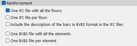
In the BIMserver.center export panel, several options are offered when activating the "Reinforcement" export:

  • One IFC file with all floors
    Generates a single IFC file that includes the reinforcement of the entire model.
  • One IFC file per floor
    Generates a separate IFC file for each floor, with the corresponding reinforcement.
  • Include the description of the bars in BVBS format in the IFC files
    Adds an additional parameter on each bar with its description in BVBS format, which provides the necessary information about the shape of each bar for its manufacture.
  • One BVBS file containing all the elements
    Generates a single file that includes all the rebar in the project.
  • One BVBS file per element
    Generates a separate file for each element in the project.

In the "Export" menu, the "Export in CSV format" option has been added. Here, users can create customised tables with different formats, data, and results of the elements in the job that are to be exported in CSV format. These tables can be saved and used in any project.

For now, the forces of columns, shear walls and walls can be exported in different configurations. Other types of tables will be implemented in future updates of the program.

In CYPECAD version 2025.c, the possibility of defining precast concrete joist floor systems and using them to design joist floor slabs has been implemented. A system or assembly is defined by the selection of a joist, a form and the thickness of the compression layer. Precast elements are selected using the manufacturer's product catalogues that have been incorporated into the program.

The program designs the optimum joist among those available for the selected assembly, as well as the reinforcement to be installed in the job in order to comply with the safety requirements established by the code. To this end, checks are carried out on the ultimate and serviceability limit states, as well as other geometric and quantity checks. To carry out the checks, the real section of the concrete is generated, both precast and poured on site, with its corresponding reinforcement.

Just as with other elements such as beams and columns, the checks can be viewed and listed in detail, and any changes made by the user to the result proposed by the program will affect the checks.

Floor slab systems are available for the following concrete standards: Spanish structural code "Código Estructural" and "Eurocode 2" (including the different national annexes). In addition to the requirements of the concrete standard, the provisions of "EN 15037" have been considered, which complements the specifications for the particular case of prefabricated joists.

In version 2025.c, the calculation of the sinking load in deep foundations using reinforced concrete piles has been implemented for the "CYPECAD", "CYPE 3D" and "Foundation elements" programs. This implementation has been included in the new "Piles: Calculation of sinking load" module.

This module complements the design of deep foundations using pile caps, allowing users to verify the bearing capacity of the piles under different load conditions, considering the characteristics of the soil and the pile itself.

The program allows users to define several ground types, including cohesive soils, granular soils and rock formations. Each soil type can be configured with its specific geotechnical properties, allowing a customised analysis of the site characteristics. Furthermore, the defined soils can be reused, which optimises the modelling and design process. Piles can be either precast or cast-in-place, with square or circular cross-sections.

The resistance to sinking is obtained by considering the resistance per tip and shaft of the soil layer in contact with the pile. The calculation method used is based on analytical formulations based on the Mohr-Coulomb equation taken from the existing specific technical specifications. The verification has been implemented for the entire set of codes available in the CYPECAD, CYPE 3D and Foundation elements programs.

The "Check "option, accessible from the editing panel of the foundation elements, allows users to consult the calculations made to verify the safety of the piles.

To use this module, the following permissions must be included in the license, depending on the program where it is to be used:

  • In CYPECAD
    "CYPECAD", “Pile caps” and “Piles: Calculation of the sinking load”.
  • In CYPE 3D
    "CYPE 3D", “Pile caps” and “Piles: Calculation of the sinking load”.
  • In Foundation elements
    "Foundation elements” and “Piles: Calculation of the sinking load”.

CYPECAD version 2025.c includes the implementation of wind load codes. In the "Implementing codes and improving their enforcement" section of the new features in version 2025.c, you can consult the codes included in all CYPE programs in this version.

In CYPECAD the following codes have been included:

  • Loads on structures. Wind loads
    • ILNAS-EN 1991-1-4:2005+A1:2010/AN-LU:2020 (Luxembourg)
    • LVS-EN 1991-1-4:2005/NA:2011 (Latvia)
    • FSS-EN 1991-1-4:2005/NA:2019 (Finland)
    • SRPS EN 1991-1-4:2005/EN:2017 (Serbia)

Version 2025.c of the CYPE apps includes the following improvements in the management of DXF and DWG file templates:

  • Reading DXF/DWG files with updated version
    As of version 2025.c, CYPE apps can read DXF/DWG files up to AutoCAD® version 2025.

  • Improved template preview
    Advanced graphic management has been implemented in the template selection and transformation panels to optimise the template drawing preview window and facilitate the movement of the drawing from this panel.

  • Simultaneous transformations on the template
    The application of the following transformations on an imported template has been improved:
    • Selecting the visible area of the template
    • Changing the coordinate origin of a template
    • Adjusting the scale of a template

As of version 2025.c, the "Drawing layouts" panel uses hardware acceleration for drafting drawings. This implementation allows users to represent and move the model more smoothly.

This panel is present in several CYPE programs, although hardware acceleration is much more noticeable in programs and projects with multiple elements (CYPECAD, CYPE 3D, CYPECAD MEP, etc.).

Serbian national annex to Eurocode 1: Actions in structures. Part 1-4: General actions - Wind actions.

Implemented in CYPECAD and Portal frame generator.

Finnish national annex to Eurocode 1: Actions in structures. Part 1-4: General actions - Wind actions.

Implemented in CYPECAD and Portal frame generator.

Latvian national annex to Eurocode 1: Actions in structures. Part 1-4: General actions - Wind actions.

Implemented in CYPECAD and Portal frame generator.

Luxembourg national annex to Eurocode 1: Actions in structures. Part 1-4: General actions - Wind actions.

Implemented in CYPECAD and Portal frame generator.

CYPE Mentor