In the 2021.a version, columns with different sections and material types can be imported from the BIM model.
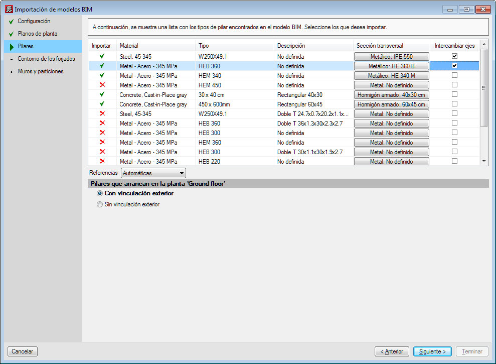
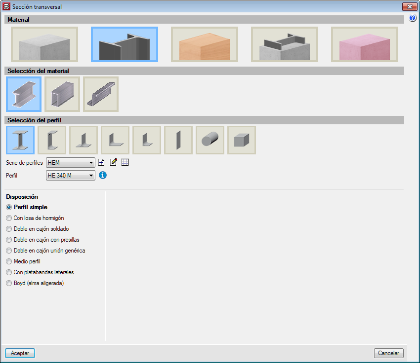
In the “Columns” stage of the BIM model import assistant, a list is displayed containing the columns that have been detected. The first column of the list allows users to activate or deactivate the import of each type of section. The columns “Material”, “Type” and “Description” show the data that is contained on the IFC file. The “Transverse section” column indicates the section that is assigned to the type of column. By pressing on each cell, the selection panel of the transverse section of the column can be accessed.
The “Switch axes” column allows users to change the orientation of the local axes of the section. This tool is required when the axes criteria of the transverse section of the IFC that is being imported is different to the axes criteria of the sections of CYPECAD.
The program assigns rectangular and circular sections automatically. For each remaining section, the corresponding CYPECAD section must be assigned. The assignment that is carried out is saved automatically for future imports.