Update history​​

CYPECAD

In the 2021.b version, the "Reports" dialogue of the "File" menu can be configured by users. The appearance of the panel that is displayed when "Reports" is pressed has changed. It shows all the reports that are available in the program. The buttons that correspond to reports that cannot be displayed in the current project are disabled.

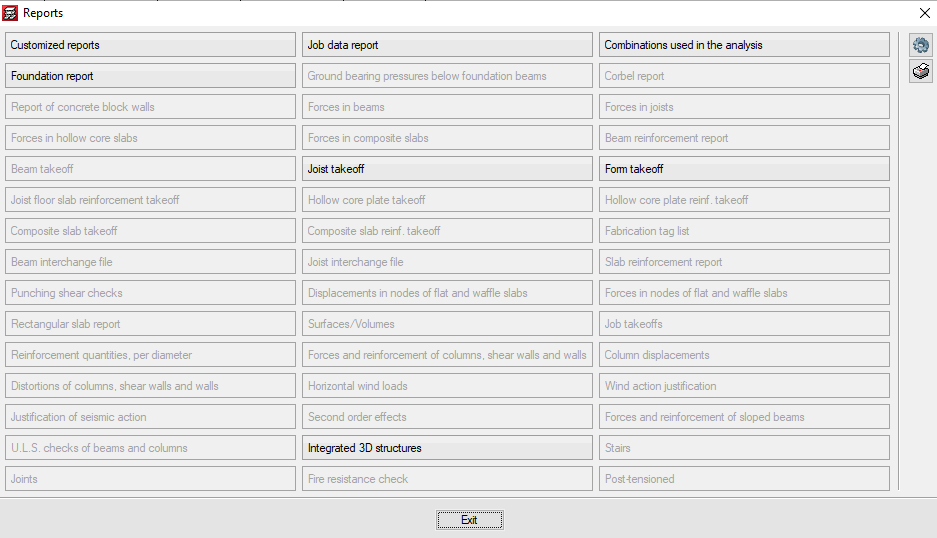
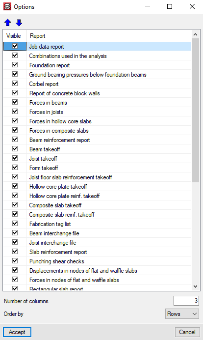
The "Options" button allows users to select which reports appear in the panel and the order in which they are displayed. This way, users can only show the reports that they usually use in the panel organised in accordance to their preference criteria.

The 2021.a version of CYPECAD also includes other minor improvements and corrections of the program that can arise in specific cases:

  • Possibility to add the options “Enter double joist”, “Check the geometry of the current group”, “Check geometry of current group and higher groups” and “Check the geometry of all groups” in the toolbar.
  • Corrections in the generation of the 3D views of floor slabs.
  • Corrections in the 3D view of beam intersections.
  • Detection of construction elements that have been defined incorrectly.
  • Corrections in the reinforcement detailing of concrete columns with generic sections.
  • Corrections in the consultation of force combinations for timber columns.

A warning is displayed in the final design report if, during the design process of floor slabs, waffle slabs or drop panels, the base reinforcement has been modified in any way. The slabs on which any changes have been carried out are indicated.

The options that are selected in “Template object snaps” are saved when the Accept button is pressed. This way the selection remains for when the program is executed in the future.

In the 2021.a version, columns with different sections and material types can be imported from the BIM model.

In the “Columns” stage of the BIM model import assistant, a list is displayed containing the columns that have been detected. The first column of the list allows users to activate or deactivate the import of each type of section. The columns “Material”, “Type” and “Description” show the data that is contained on the IFC file. The “Transverse section” column indicates the section that is assigned to the type of column. By pressing on each cell, the selection panel of the transverse section of the column can be accessed.

The “Switch axes” column allows users to change the orientation of the local axes of the section. This tool is required when the axes criteria of the transverse section of the IFC that is being imported is different to the axes criteria of the sections of CYPECAD.

The program assigns rectangular and circular sections automatically. For each remaining section, the corresponding CYPECAD section must be assigned. The assignment that is carried out is saved automatically for future imports.

Soil-structure interaction (footings and pile caps) is a CYPECAD module with which the settlement of the foundations and their interaction with the rest of the structure, regarding forces and deformations, can be considered. The soil-structure interaction is considered by defining elastic stiffness constants for the foundation elements.

For footings, the stiffness is entered as the subgrade modulus. Similarly, for pile caps, users must define the axial stiffness for each pile, which is determined by the ratio between its load and the settlement that is produced.

More information.

  • Improvements in wall meshes when there is a complex geometry.
  • Adjustment of beam lengths in walls with a displaced axis.
  • Design of dual pitch beam frames in some cases where it was not carried out.
  • Application of fire safety checks in specific cases where they were not carried out.
  • Generation of beams at positions that are very eccentric with respect to the beam.
  • View contour maps on very large surfaces.
  • Consult the deformed shape of certain walls, which was not displayed previously.
  • View the deformed shape of the project in cases where there is an elastic fixity in the connections to an integrated 3D structure.
  • "Guid" and "Category" are added to the elements of the integrated 3D structures to export to IFC and glTF format.
  • Wall starter beams are exported to IFC, which previously, were not generated.
  • The dialogue panels in which the chapters of the reports are selected can now be redesigned.
  • Correction in the import of construction elements from IFC format.
  • The position of the starts is included in the "Column layout" table of the floor layout plan.
  • The drawing of the wall elevation plan has been corrected for when there is a floor slab or beam with a depth greater than 1 metre.
  • Correction of the error in the discretisation process, for the specific case of a block wall that begins on another wall.
  • ASCII files with new wind loadcases can be imported.
  • Incorrect beam intersection problem warnings have been deleted.
  • The loads of the construction elements are now included in the "Seguridad estructural" section of "Memorias CTE" and "CYPE Memorias CTE".
  • The diameters that are used for the transverse reinforcement of concrete walls, are those defined for column stirrups ("Steel in bars" > "Options for columns, shear walls, walls and corbels" > "Reinforcement tables" > "Column reinforcement tables" > "Available diameters" > "Stirrups").
  • The diameters that are used for the top reinforcement of lightweight panels for which this reinforcement is not already defined, are those defined in the top reinforcement tables for joists ("Floor slabs" > "Rib top reinf." > "Joist top reinforcement tables" > "Diameters used").

The allowable range of wall thicknesses has been broadened. In earlier versions, the maximum width was fixed at 1 metre. As of the 2020.f version, users can enter walls with a thickness greater than 1 metre.

The walls and partitions of the architectural model are imported as construction elements. In earlier versions, these construction elements were generated at the same position as the adjustment line of walls or partitions. As of the 2020.f version, construction elements will be generated at the axis of the imported walls or partitions.

In earlier versions, when the "Move column/shear wall" option was used, dxf/dwg templates were snapped to. As of the 2020.f version, the program snaps to column and floor slab outlines of the BIM model.

An option has been implemented which allows to optionally reduce the fixity coefficient at the last floor when editing each column. From the "Fixity coefficients" panel, users can select, at the top of the column of the last floor, whether to apply the reduced or unreduced fixity coefficient.

Forces and displacements that lie between a maximum and minimum value, defined by users, can now be viewed in the "Contour maps" tab. Zones with force or displacement values that lie outside the defined range are not displayed.

CYPE Mentor