The 2020.e version includes the check of columns and timber bars with circular sections for the following design codes:
- CIRSOC 601
- ANSI/AWC NDS-2015


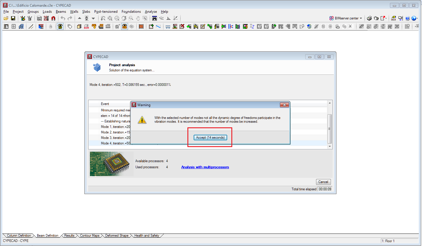
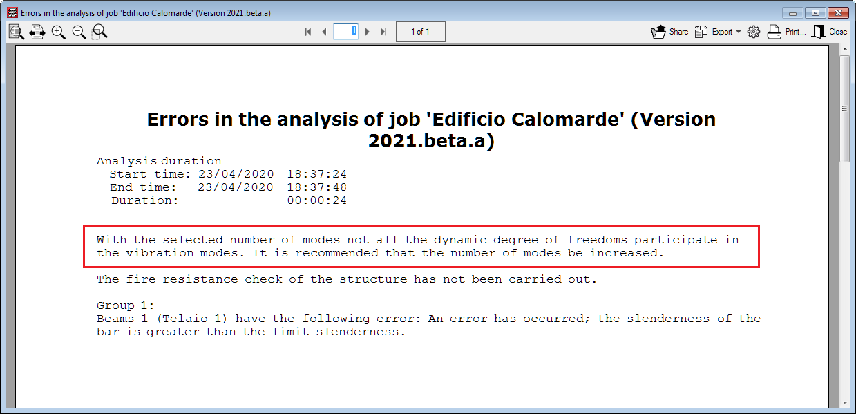
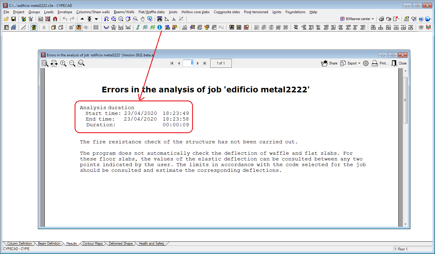
In previous versions, certain warnings interrupted the analysis until users accepted them. As of the 2020.e version, these warnings are displayed with a twenty second wait before closing automatically. In any case, these errors appear in the final report. This improvement allows the analysis to continue and finish when these warnings appear without the need for users to be on the lookout.
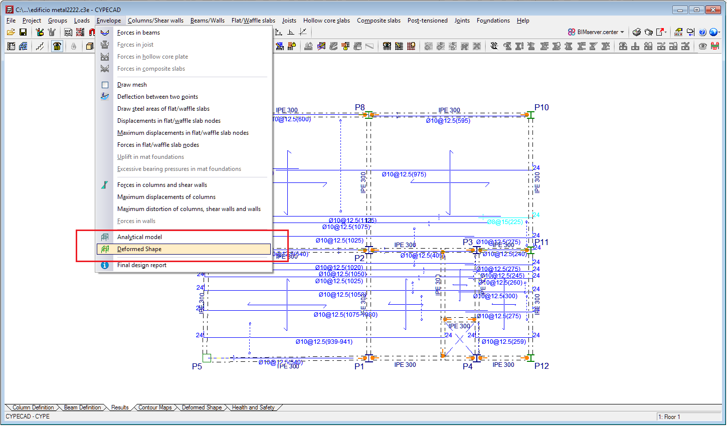
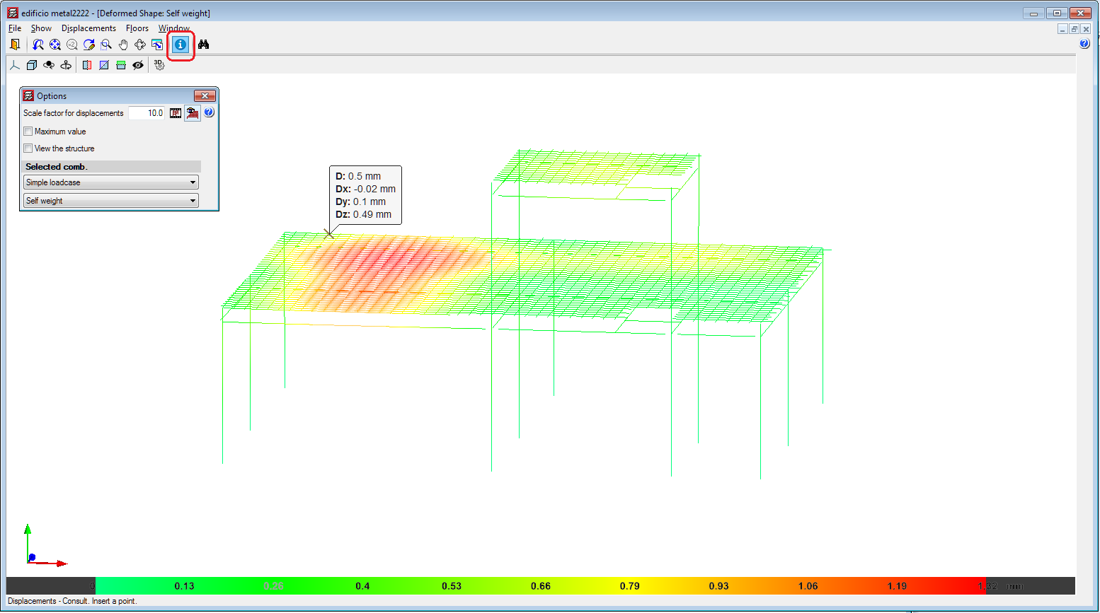
In the 2020.e version of CYPECAD, users can consult results in the 3D view of the deformed shape. This window is accessed from the "Deformed shape" tab, and also (as of the 2020.e version) from the "Deformed shape" option of the "Envelopes" menu of the "Results" tab.
By activating the "Consult" button in the window of the 3D view of the deformed shape, the program displays the displacement values of the points of the structure on which the mouse cursor is placed.
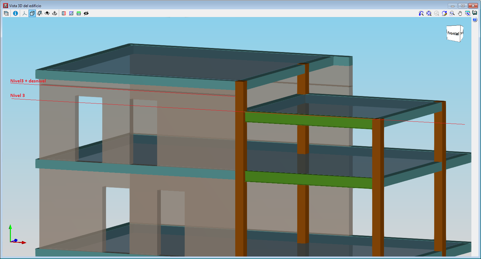
With this improvement, which is included in the "Sloped floor slabs/ El. Changes" option in the "Walls" menu, users can define an opening in a wall when the upper elevation of the opening is higher than the elevation of the floor. This improvement is useful when intermediate floors have to be defined in the project, such as roof slabs at different heights.
As of the 2020.e version, the start time, end time and duration of the analysis is added to the final design report.
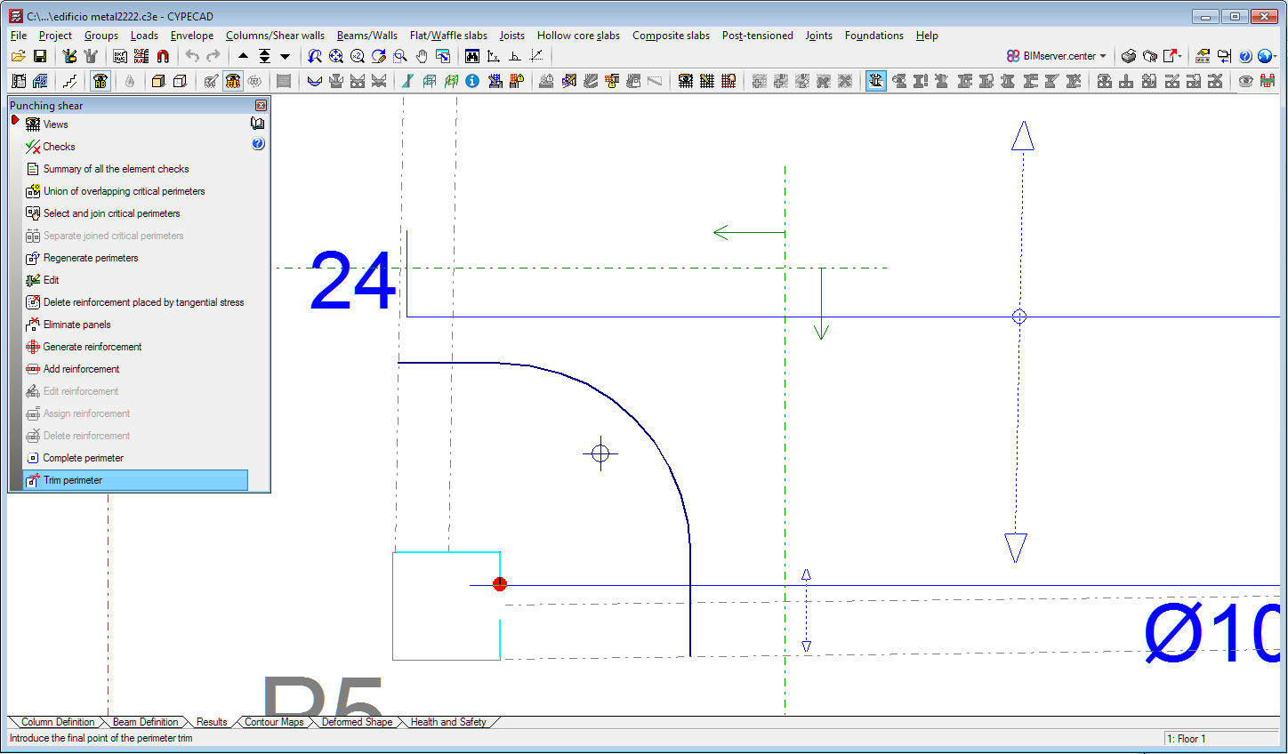
In previous versions to the 2020.e version, users could complete or trim the critical perimeter and reinforcement perimeter in the punching shear check. As of the 2020.e version, it is also possible to complete or trim the perimeter of the support.
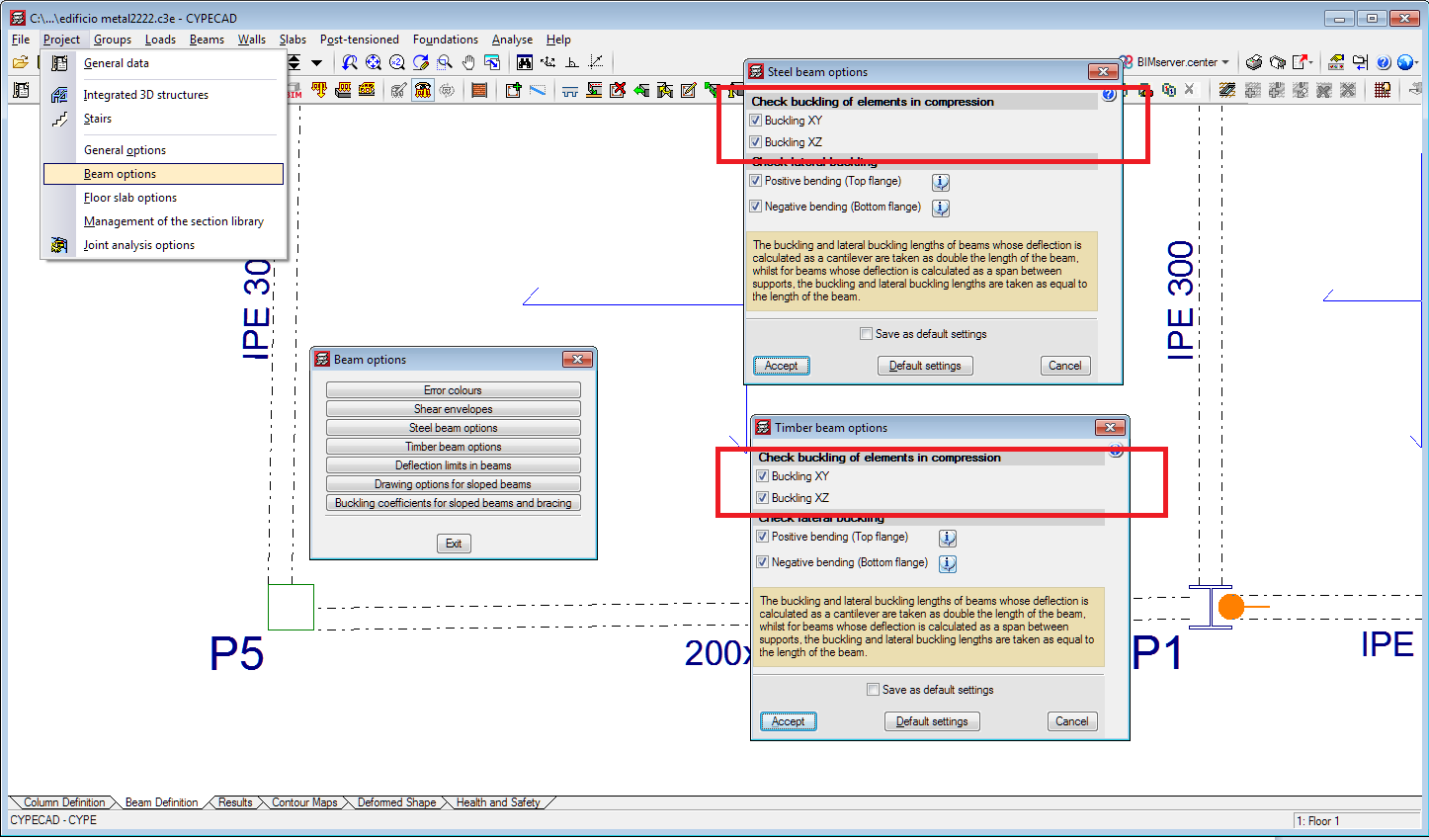
In the 2020.e version, an option has been implemented to activate or deactivate the buckling check for steel or timber beams that are subjected to compression in the XY plane and in the XZ plane (in CYPECAD only beams that are disconnected from the rigid diaphragm can be subjected to compression). In previous versions, compressed steel or timber beams were always checked for buckling.
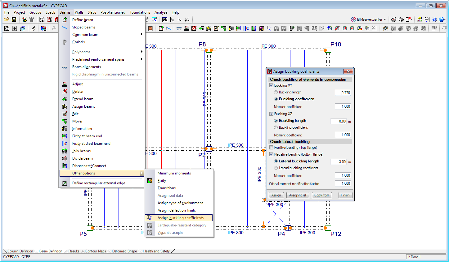
Users can assign buckling and lateral buckling coefficients to steel and timber beams. This option allows users to assign different values to each beam.
This option is located in the Beam Definition tab (Beams > Other options > Assign buckling coefficients).
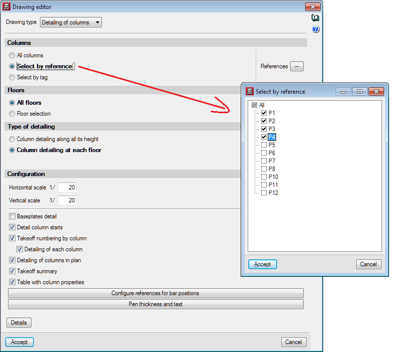
In the 2020.e version, users have the possibility to obtain the "Column details" and "Column schedule drawings" for columns that have been selected by reference.