Update history
CYPECAD
Assign buckling and lateral buckling coefficients to steel and timber beams
- Published on
- 2020.e
Selection of columns in "Column details" and "Column schedule" drawings
- Published on
- 2020.e
Column and beam tags
In the 2020.e version, the management of column and beam tags has been implemented. In the portal frames, column detail and column schedule drawings, users can select frames and columns depending on the tags that have been assigned.
Users can access the "Tags" panel from the "Groups" menu in the "Beam Definition" tab, where three options have been implemented:
- Assign
Users can assign tags to columns and beams. The list of tags can be managed from this option. Marked tags will be assigned to the elements that have been selected on the current floor. - Delete
Allows users to delete tags that have been assigned to columns and beams. Marked tags will be deleted from the elements that have been selected on the current floor. - Edit
Allows users to edit tags that have been assigned to an element.
- Published on
- 2020.e
Code implementation. ASCE/SEI 7-16 (USA)
ASCE/SEI 7-16: Minimum Design Loads for Buildings and Other Structures.
Implemented in CYPECAD and CYPE 3D.
- Published on
- 2020.e
Code implementation. ASCE/SEI 7-16 (USA)
ASCE/SEI 7-16: Minimum Design Loads for Buildings and Other Structures.
Implemented in CYPECAD.
- Published on
- 2020.e
Corrections made in CYPECAD
- The results of timber columns are shown for the NBR 7190:1997 code of Brazil.
- The results of columns that have not been designed after the analysis can be edited.
- Columns that have been rotated and their fixed point is not the centre can be exported to IFC format.
- The initial stressing load is shown on drawings and reports.
- The wind loads report displays the units correctly when it is viewed from the “General data” panel.
- Published on
- 2020.d
New section library
- Published on
- 2020.c
Wind load justification report for “NBR 6123” and “NF EN 1991-1-4/NA”
In the 2020.c version, the “Wind load justification report” has been implemented for the following codes:
- NBR 6123
Forças devidas ao vento em edificações (Brazil) - NF EN 1991-1-4/NA
Document National d’Application pour la France.
Eurocode 1: Actions sur les structures.
Partie 1-4: Actions générales – Actions du vent.
This report was implemented for other codes in previous versions and will continue to be implemented for others progressively.
- Published on
- 2020.c
Move texts, introduced in “Editing resources”, from the “Drawings editor” of the “Drawing composition”
- Published on
- 2020.c
Options to manage beam alignment references
Some options (Options, Reorganise, Assign number, Assign reference and Multiple assignment) have been grouped or added in the “Beam alignment” panel (“Beam Definition” > Beams > Beam alignments).
Please note that, as of the 2020.c version, beam alignment references will remain even if beams are added or deleted.
Options
The following existing tools have been grouped in Options:
- Frame order criteria
- Base reference of the frames (Project)
- Base reference of the frames (By group)
Assign number
This option allows users to assign a different alignment or frame number to the one that has been generated automatically by the program in accordance with the criteria that has been specified in “Generate alignments”.
Assign reference
With this option, users can assign a reference to an alignment.
Multiple assignment
Using this tool, users can assign the following data to a selection of alignments:
- Number
The first number from which the numbers will continue is defined here. - Reference
Users define the reference of the first frame, as of which the remaining references will be assigned by increasing the last symbol alphabetically or numerically. - References (horizontal and vertical)
The references of the first vertical and first horizontal frames are defined, as of which the remaining references will be assigned by increasing the last symbol alphabetically or numerically.
- Published on
- 2020.c
Improvements in the column introduction and editing panel
The appearance of the dialogue box where columns are introduced and edited has been modified. The table where users can edit the geometry of the column at each floor has been moved to the right of the column data.
With the distribution that existed in previous version, users could not view all floors simultaneously if the structure contained a high number of floors.
- Published on
- 2020.c
Options to import floor slab outlines from the BIM model
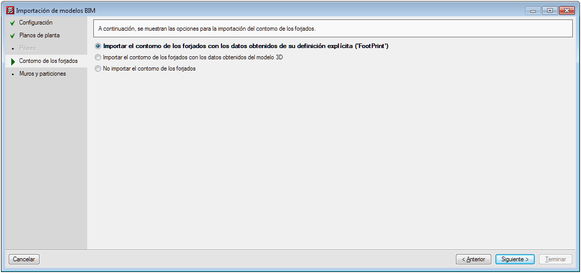
Several options have been implemented in CYPECAD to import floor slab outlines:
- Import floor slab outlines with the data obtained from explicit definition (FootPrint).
- Import the floor slab outlines with the data obtained from the 3D model.
- Do not import floor slab outlines.
The architectural models can contain different information depending on the program and the program version that has generated them. Some programs export the floor plan representation of the floor slabs (FootPrint) as well as the 3D model. Up until the 2020.b version, CYPECAD imported the representation of the floor slabs (FootPrint) if it had been defined, otherwise, it offered users the possibility to import them based on the 3D model.
These import options have been implemented because errors were observed in the IFCs that came from the latest versions of some programs, where the outlines were exported correctly but the outlines of the openings were not exported
- Published on
- 2020.c


