As of the 2019.e version, the applications that are integrated in the Open BIM workflow can consult the BIM information contained in the GLTF format files in the same way as on the BIMserver.center platform.


As of the 2019.e version, the applications that are integrated in the Open BIM workflow can consult the BIM information contained in the GLTF format files in the same way as on the BIMserver.center platform.
As of the 2019.e version, the 3D representation in the applications that are integrated in the Open BIM workflow contains the elements of the application itself as well as those contained in the GLTF files exported by the rest of the applications whose IFC files have been linked to the model.
The 2019.e version includes a new 3D view system in most of its programs: CYPECAD, CYPE 3D and the entire family of applications integrated in the Open BIM workflow. It will be incorporated progressively in other programs.
The properties of the system are:
For this viewing system to operate correctly, the applications require a video card that is compatible with OpenGL 3.3 or higher.
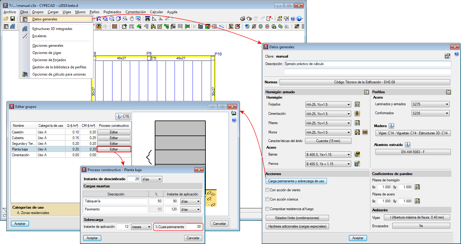
As of the 2019.d version, CYPECAD, CYPE 3D and Continuous beams allow users to edit the percentage of live load to be considered as quasi-permanent load to take it into account when calculating the differed deflection. To do so, the “Construction process” panel has been included in the “% Quasi-permanent” field.
The panel can be accessed as follows:
In previous versions, each time a file was exported to IFC format, the program would propose a default path: “C:\CYPE Ingenieros\Export files\CYPECAD\**.ifc”. As of the 2019.d version, the program remembers the path to which the file was exported previously, even if it belongs to a different project.
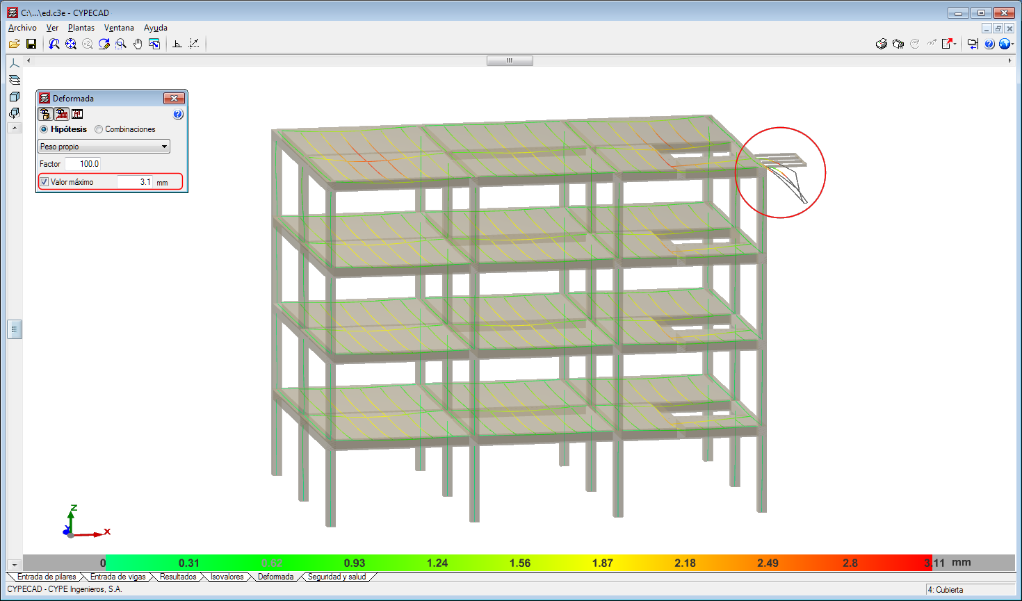
As of the 2019.d version, users can establish a displacement limit as of which the values of the deformed shape are not displayed.
In other words, the deformed shaped of the structure is still represented with the scale factor that users have specified regardless of whether the indicated limit has been exceeded or not. What happens now is that the points that exceed the displacement limit are displayed in black.
To do so, the “Maximum value” option has been included in the “Deformed shape” panel that is represented in the “Deformed shape” tab.
This tool helps users to view the values of the deformed shape, discarding the parts with a displacement value that is greater than that established by users.
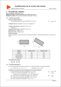
New for the 2019.d version is the “Wind loads justification report” for CIRSOC 102-2005 (Reglamento Argentino de Acción del Viento sobre las Construcciones) and ASCE/SEI 7-05 (Minimum Design Loads for Buildings and other Structures).
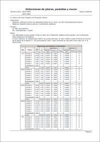
As of the 2019.d version, the distortions report also includes the results of the shear walls, besides those of the columns and walls.
Before the 2019.a version, this report only contained the results for columns. As of the 2019.d version, walls were added to the distortions reports, and now, the three types of supports are included (columns, shear walls and walls).

Activate/deactivate automatic column groups
Up until the 2019.d version, the program automatically grouped columns that had the same reinforcement and geometry each time they were designed. With the 2019.d version, the columns can be designed without them being grouped automatically. To do so, the “Automatic groups” option has been implemented (Project > General data > “By position” button > “Options for columns, shear walls, walls and corbels” > “Design/Code checks” > “Column groups”).
The “Column groups” option is active by default, and so the program will operate as it has been doing so until now regarding the column groups, i.e. automatically grouping them each time they are designed.
If the option is deactivated, the program will no longer group them automatically. In this case, the first time they are defined, all the columns will appear ungrouped. The program will never modify column groups that users have defined, even if this option has been deactivated, unless the columns have undergone changes in their dimensions, rotations, floor groups they go through, etc.
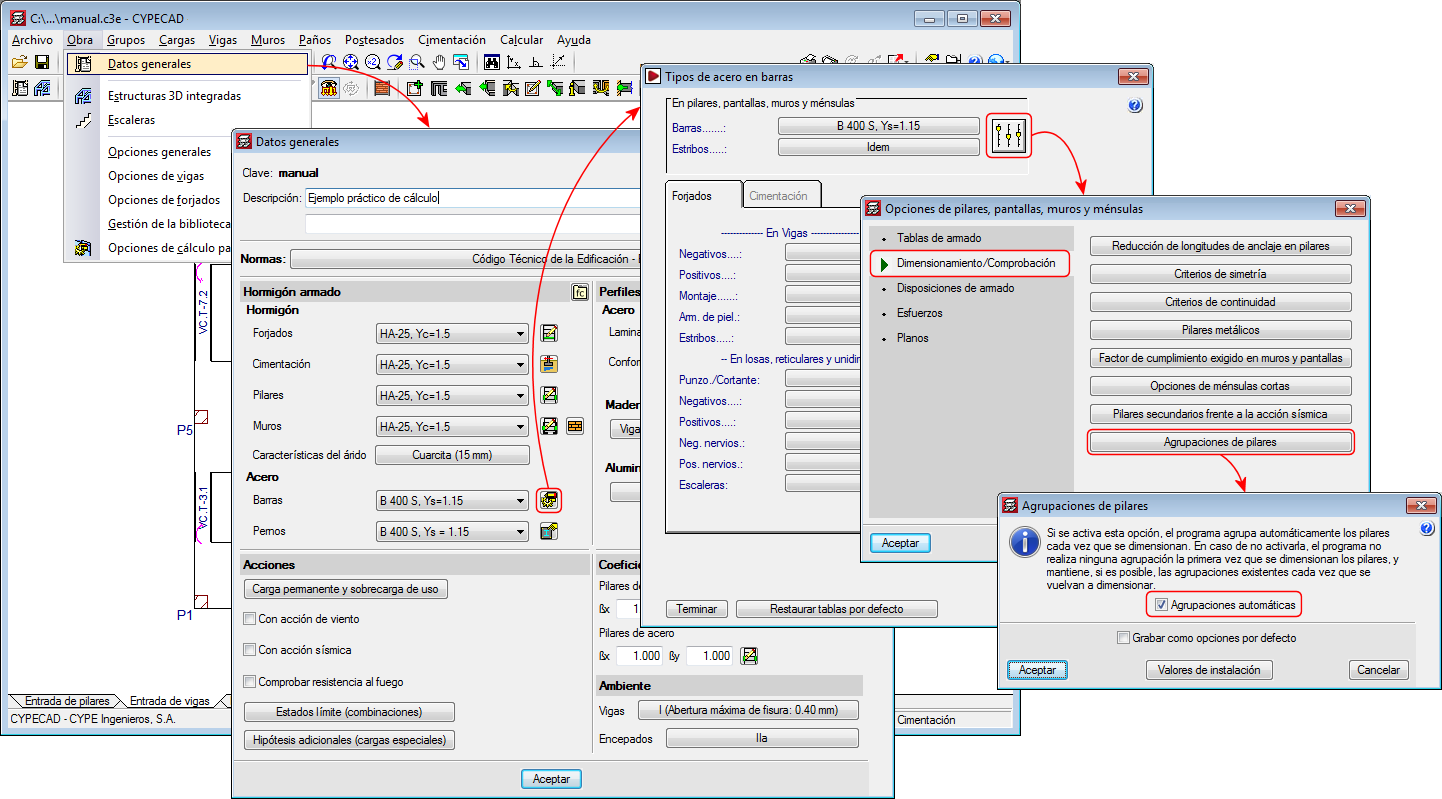
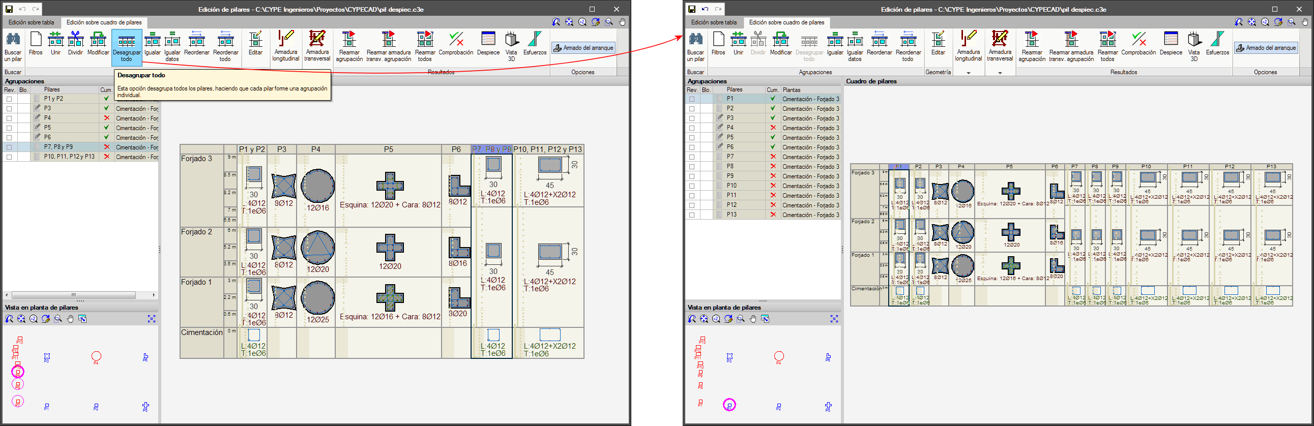
Undo column groups
A new option, “Ungroup all”, has been included in the column schedule. This option ungroups all the columns, leaving each column as an individual group.