As of the 2019.b version, the forces acting in the floor plan are displayed in the frame editor for frames that are disconnected from the rigid diaphragm.
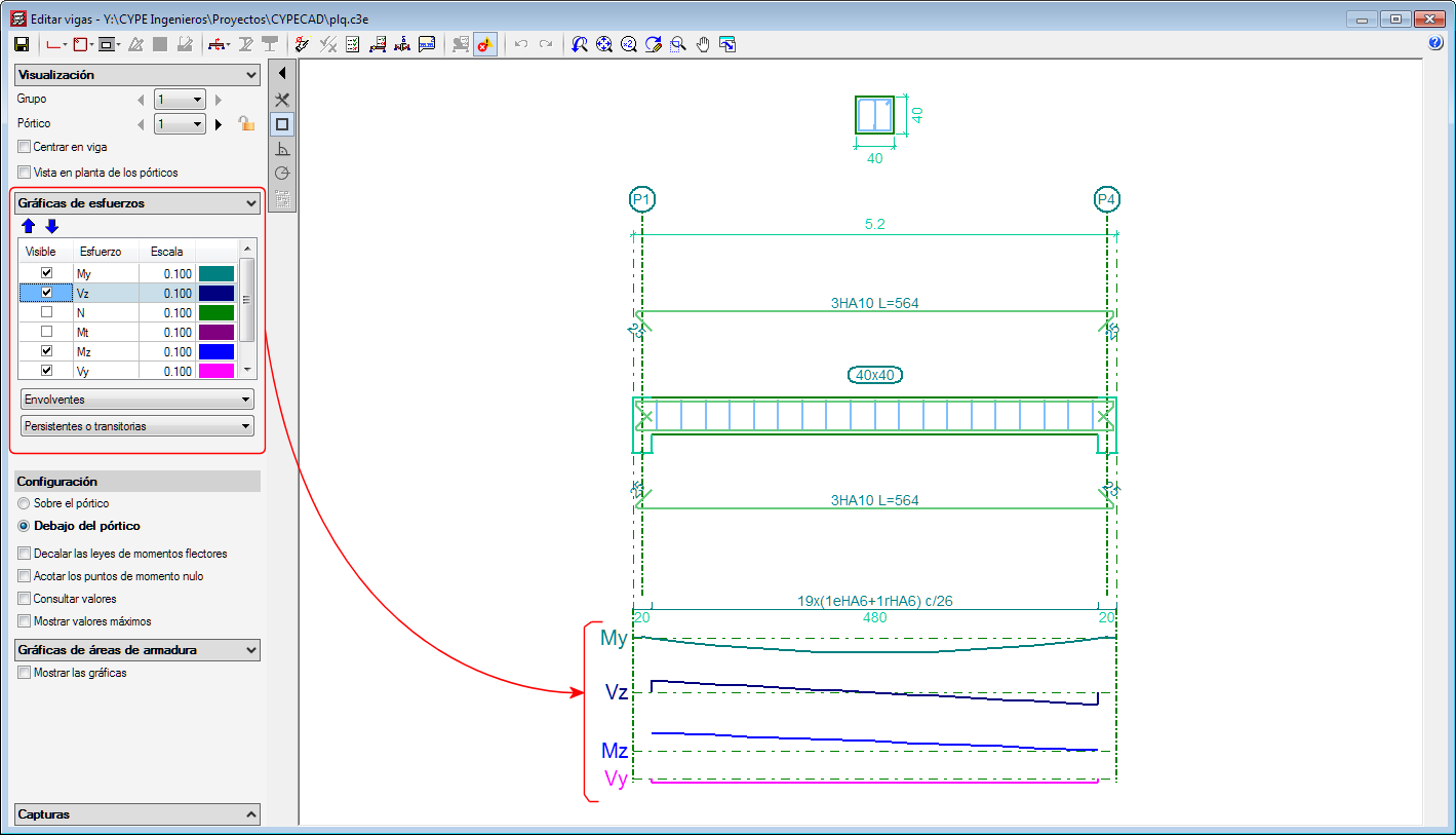


As of the 2019.b version, the forces acting in the floor plan are displayed in the frame editor for frames that are disconnected from the rigid diaphragm.
In the 2017.a version, a new option was implemented in the program where users could define the seismic-resistant category of beams, and in the 2017.c version, of beams. As of the 2019.b version, the seismic-resistant category of columns can be defined.
Secondary structural elements against seismic action are those that are not part of the seismic-resistant system of the building against this action.
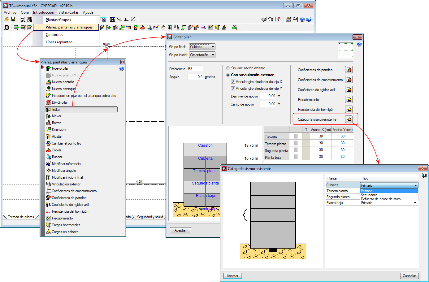
As of the 2019.b version, CYPECAD allows users to assign and define three seismic-resistant categories for columns:
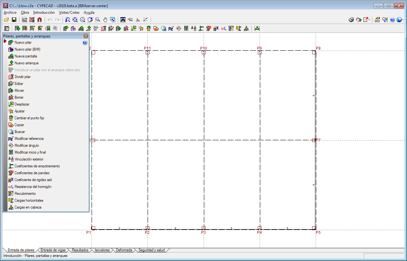
By default, all the columns of a project are considered as primary. It is users who decide which columns are to be considered as secondary or as wall edge reinforcement. For this purpose, the "Seismic Resistant Category" option has been implemented in the column introduction and edit dialogues. With this option, the desired seismic-resistance category can be assigned to each column span.
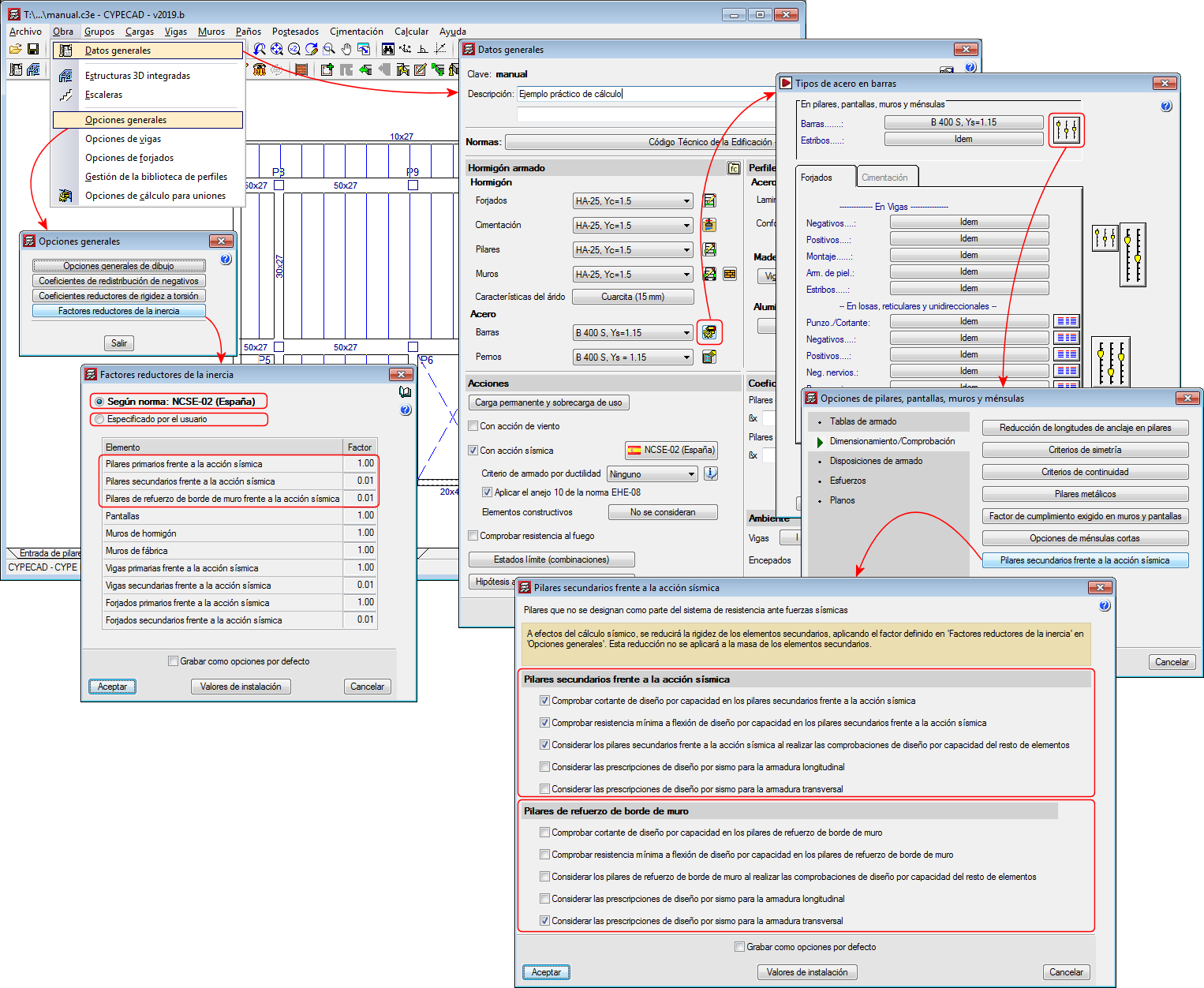
For the purposes of the seismic analysis, the stiffness of the secondary elements will be reduced by applying the factors defined in the "Inertia reduction factors" dialogue ("Project"> "General options" > "Inertia reduction factors”). This reduction will not be applied to the mass of the secondary elements.
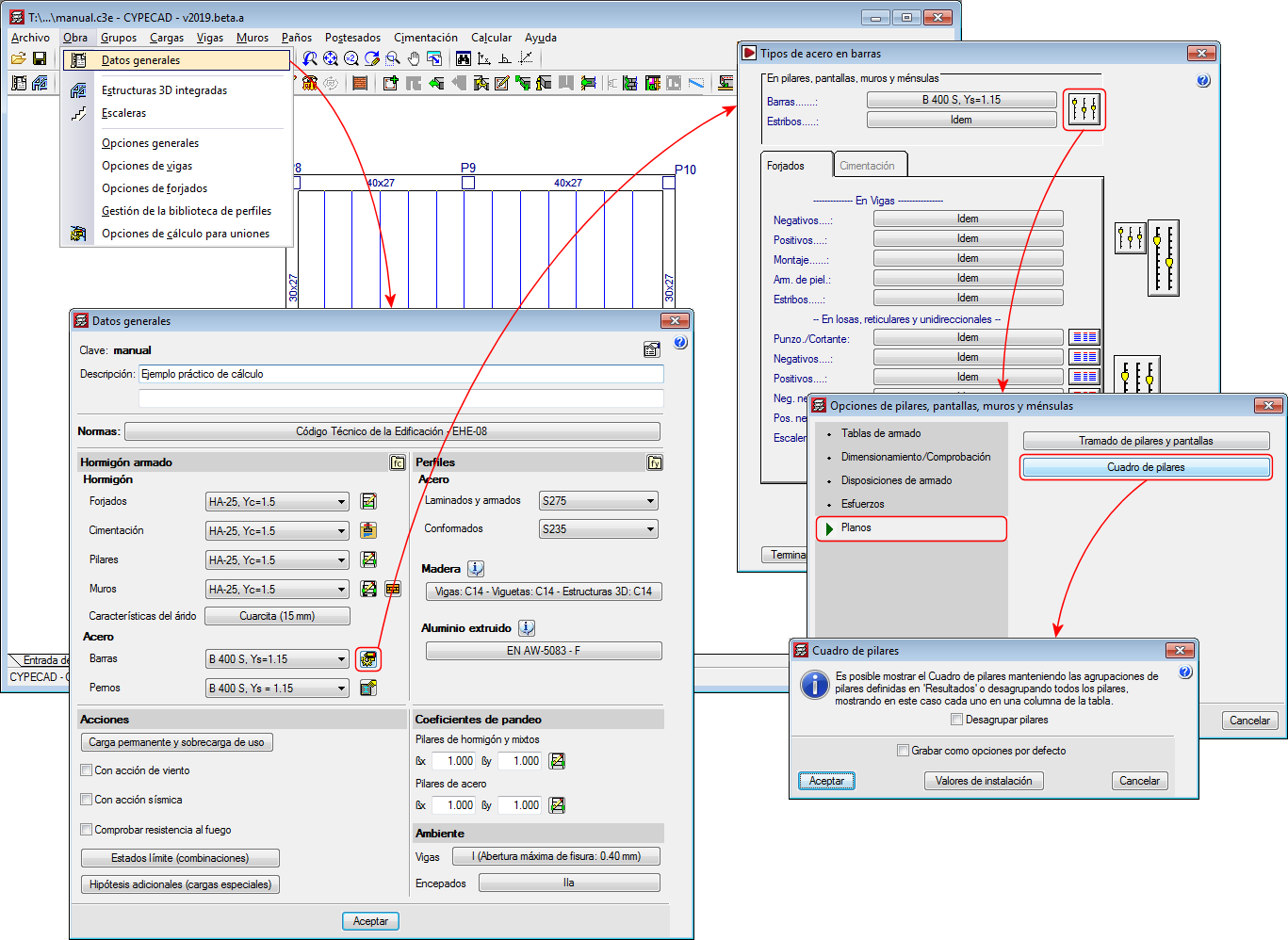
In terms of capacity design and seismic design requirements, the design and verification options defined in the “Secondary columns against seismic action” dialogue will be applied to the "secondary columns" and the "wall edge reinforcement columns" ("Project" menu> "General data"> "By position" button> "Options for columns, shear walls, walls and corbels”> "Design/ Code checks" section> "Secondary columns against seismic action" option).
The indicated inertia reduction factors and the capacity design options depend on the selected seismic code. Users, however, can define other reduction factors and select the capacity design options to apply.
For all these options to be active, users must have activated the seismic analysis with a seismic code that is compatible with the selected concrete code.
As of the 2019.a version, the Column schedule can be displayed showing the column groups defined in “Results” or ungrouped, in which case each column will be displayed in a column of the schedule.
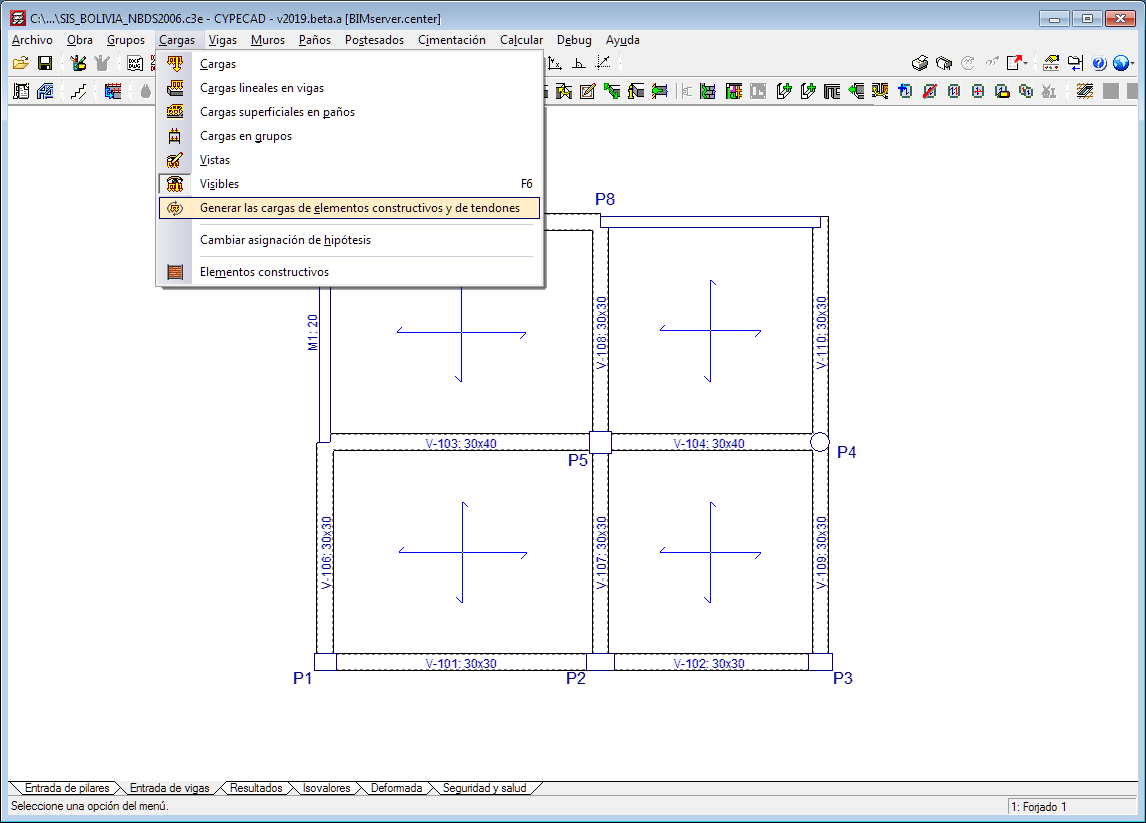
The option “Update line loads of construction elements and post-tensioned tendons” has been implemented in the “Loads” menu in the “Beam Definition” tab.
As of previous versions, the program calculates the line loads of construction elements ( “Beam Definition” tab > "Loads" menu > "Construction elements" option) and post-tensioned tendons ("Beam Definition" tab > "Post-tensioned" menu). If changes were made in these elements or in others related to them that could affect self-weight values, the program did not recalculate the loads until the project was analysed or until drawings or reports were obtained.
As of the 2019.a version, when users select the new option: “Update the loads of construction elements and tendons”, recalculates the aforementioned loads, which allows users to view their values on-screen after the modifications have been made, without the need of having to analyse the project or print drawings or reports.
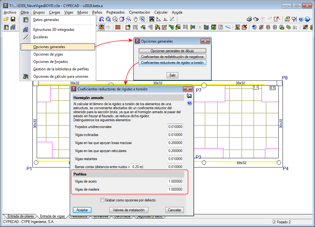
Since previous versions, torsional stiffness reduction coefficients can be defined for concrete beams. As of the 2019.a version, it is also possible to reduce the torsional stiffness for steel beams and timber beams. These coefficients can be edited in the "Torsional stiffness reduction coefficients" dialogue (Project > General options > Torsional stiffness reduction coefficients).
The “Columns, shear walls and walls” and “Floors/Groups” menus in the “Column Definition” tab opens as a floating window to access the options it contains more easily whilst users are working with them.
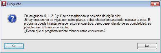
Since the 2018.h version, when a column that is connected to beams on a floor is moved, the beams do not move automatically with the column. Neither are the beams reorganized when a new column is introduced and cuts existing beams. Due to this, the intersections between columns and beams must be recreated when columns are added or moved.
As of version 2019.a the program asks a question, and users can choose to either automatically recreate the intersections or to take no automatic action (in which case, users will manually recreate the beam-column intersections afterwards). Depending on the complexity, it is possible that the program will not be able to automatically resolve certain intersections, and so the program will warn of invalid results.
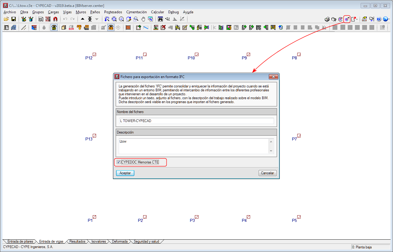
As of the 2019.a version, CYPECAD projects that are connected to a BIM model of the BIMserver.center platform allow for the necessary information to be exported to create the "Structural security" and "Security in case of fire - SI 6" sections of the Project report with the CYPE Memorias CTE program, which has also been implemented in this version.