Update history​​

CYPECAD

As of the 2019.d version, the distortions report also includes the results of the shear walls, besides those of the columns and walls.

Before the 2019.a version, this report only contained the results for columns. As of the 2019.d version, walls were added to the distortions reports, and now, the three types of supports are included (columns, shear walls and walls).

Activate/deactivate automatic column groups

Up until the 2019.d version, the program automatically grouped columns that had the same reinforcement and geometry each time they were designed. With the 2019.d version, the columns can be designed without them being grouped automatically. To do so, the “Automatic groups” option has been implemented (Project > General data > “By position” button > “Options for columns, shear walls, walls and corbels” > “Design/Code checks” > “Column groups”).

The “Column groups” option is active by default, and so the program will operate as it has been doing so until now regarding the column groups, i.e. automatically grouping them each time they are designed.

If the option is deactivated, the program will no longer group them automatically. In this case, the first time they are defined, all the columns will appear ungrouped. The program will never modify column groups that users have defined, even if this option has been deactivated, unless the columns have undergone changes in their dimensions, rotations, floor groups they go through, etc.

Undo column groups

A new option, “Ungroup all”, has been included in the column schedule. This option ungroups all the columns, leaving each column as an individual group.

The improvements that have been implemented in the application of these codes can be seen in the “Justification report of the wind loads in accordance with CIRSOC 102-2005 and ASCE/SEI 7-05” section of the new features of CYPECAD on this webpage.

  • The error that appeared when the position of steel columns was modified in projects that included steel connections has been solved.
  • The error that arose when a project was analysed in which an opening had been introduced in a wall in an area where a column ended has been corrected.
  • The loads that appear in the corbels reports are shown in the unit system that has been selected in the program.
  • Errors that could appear when using the "F6" key (loads visibility on plan) in a tab that is not the “Beam Definition” tab are corrected.
  • The selection of the visible templates (DXF, DWG or BIM model) that users chose in the “Column Definition” tab was lost when they changed to a different tab.
  • When a project is created from a BIM model, the column templates are activated by default in the "Column Definition" and the floor slab outline templates in the “Beam Definition” tab.

As of the 2019.b version, the forces acting in the floor plan are displayed in the frame editor for frames that are disconnected from the rigid diaphragm.

In the 2017.a version, a new option was implemented in the program where users could define the seismic-resistant category of beams, and in the 2017.c version, of beams. As of the 2019.b version, the seismic-resistant category of columns can be defined.

Secondary structural elements against seismic action are those that are not part of the seismic-resistant system of the building against this action.

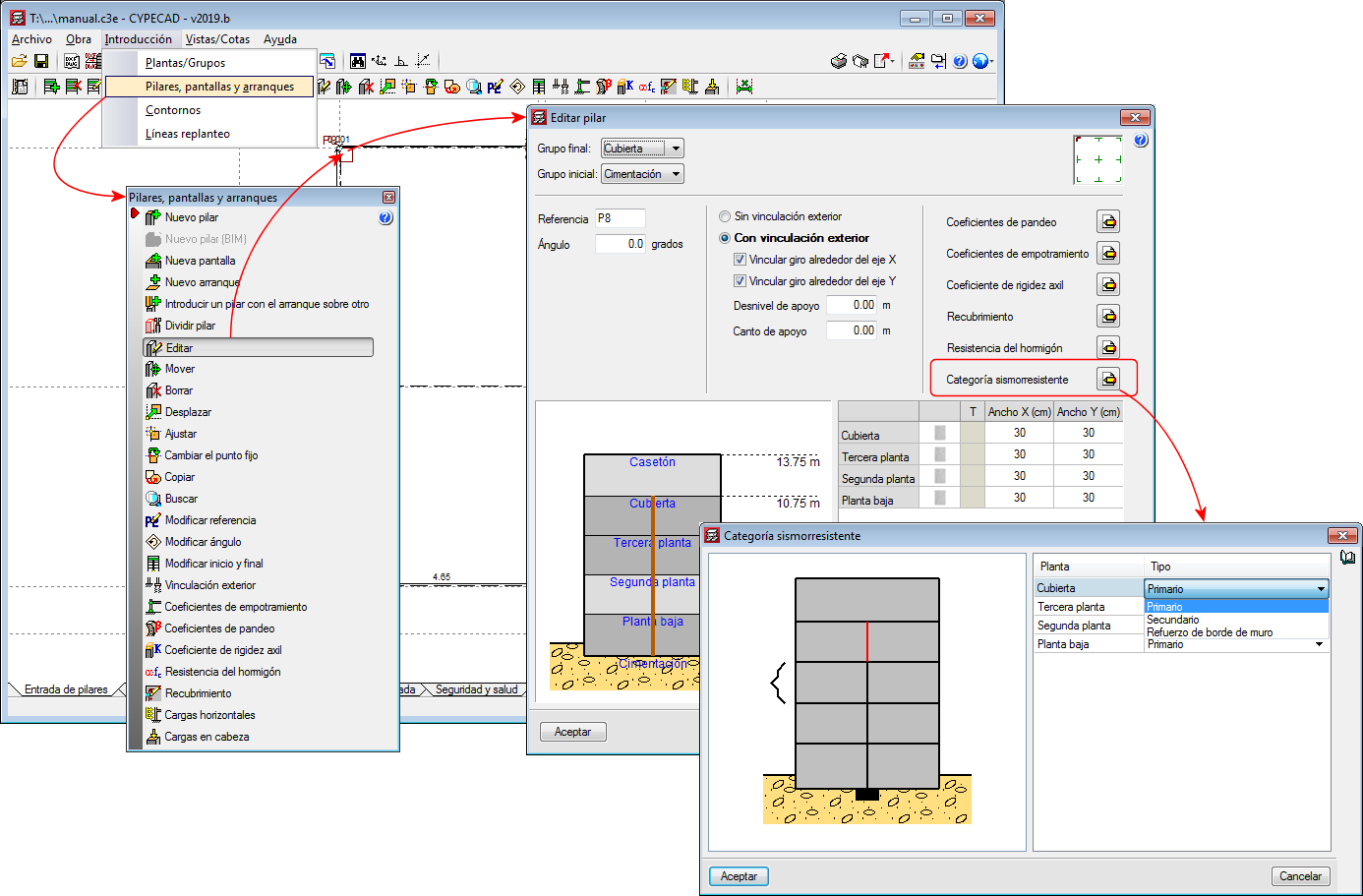
As of the 2019.b version, CYPECAD allows users to assign and define three seismic-resistant categories for columns:

  • Primary column
  • Secondary column
  • Wall edge reinforcement column

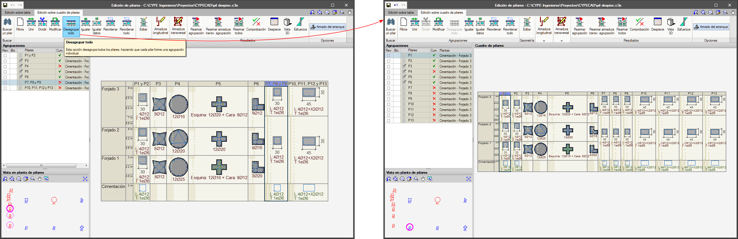
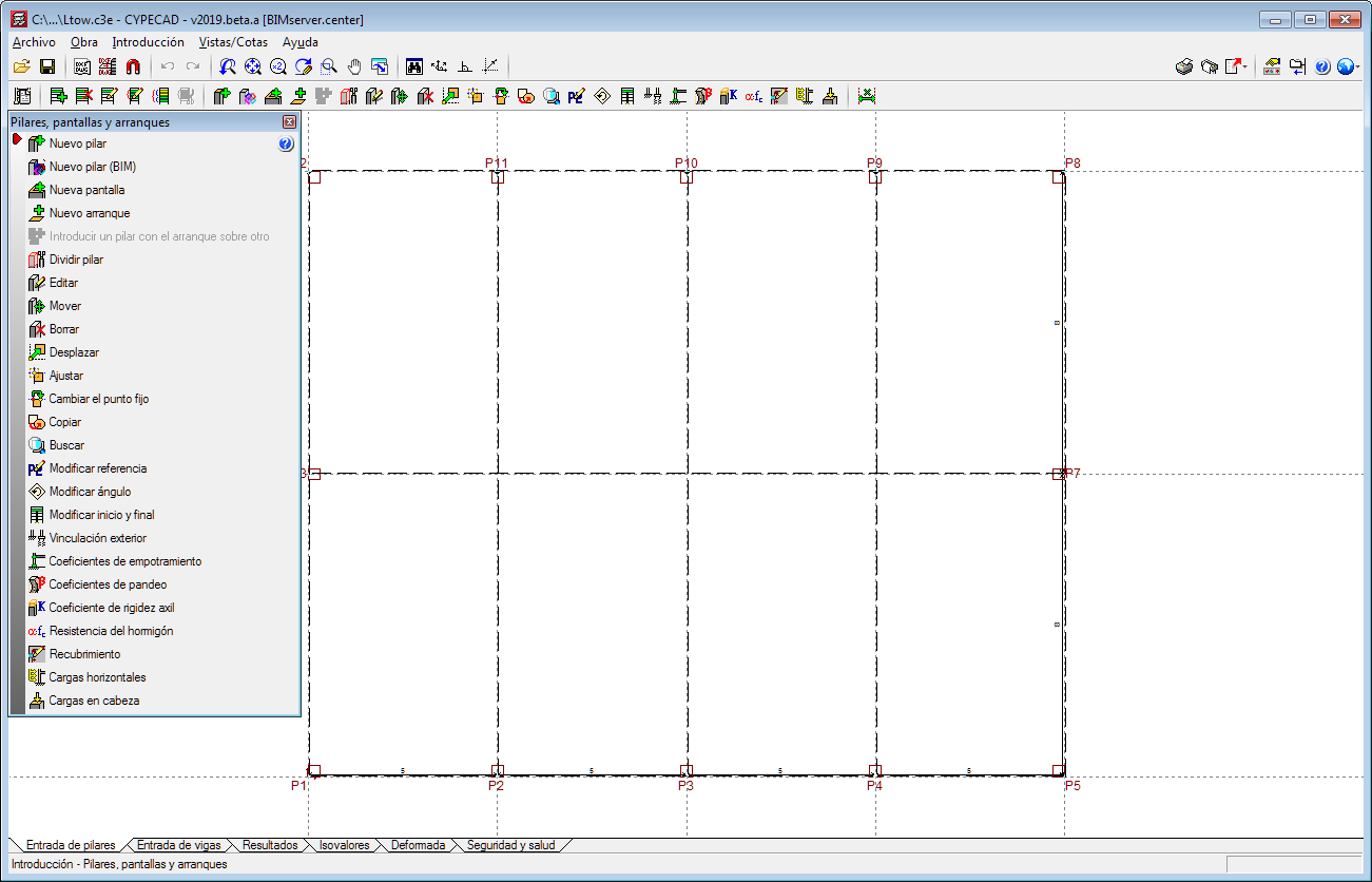
By default, all the columns of a project are considered as primary. It is users who decide which columns are to be considered as secondary or as wall edge reinforcement. For this purpose, the "Seismic Resistant Category" option has been implemented in the column introduction and edit dialogues. With this option, the desired seismic-resistance category can be assigned to each column span.

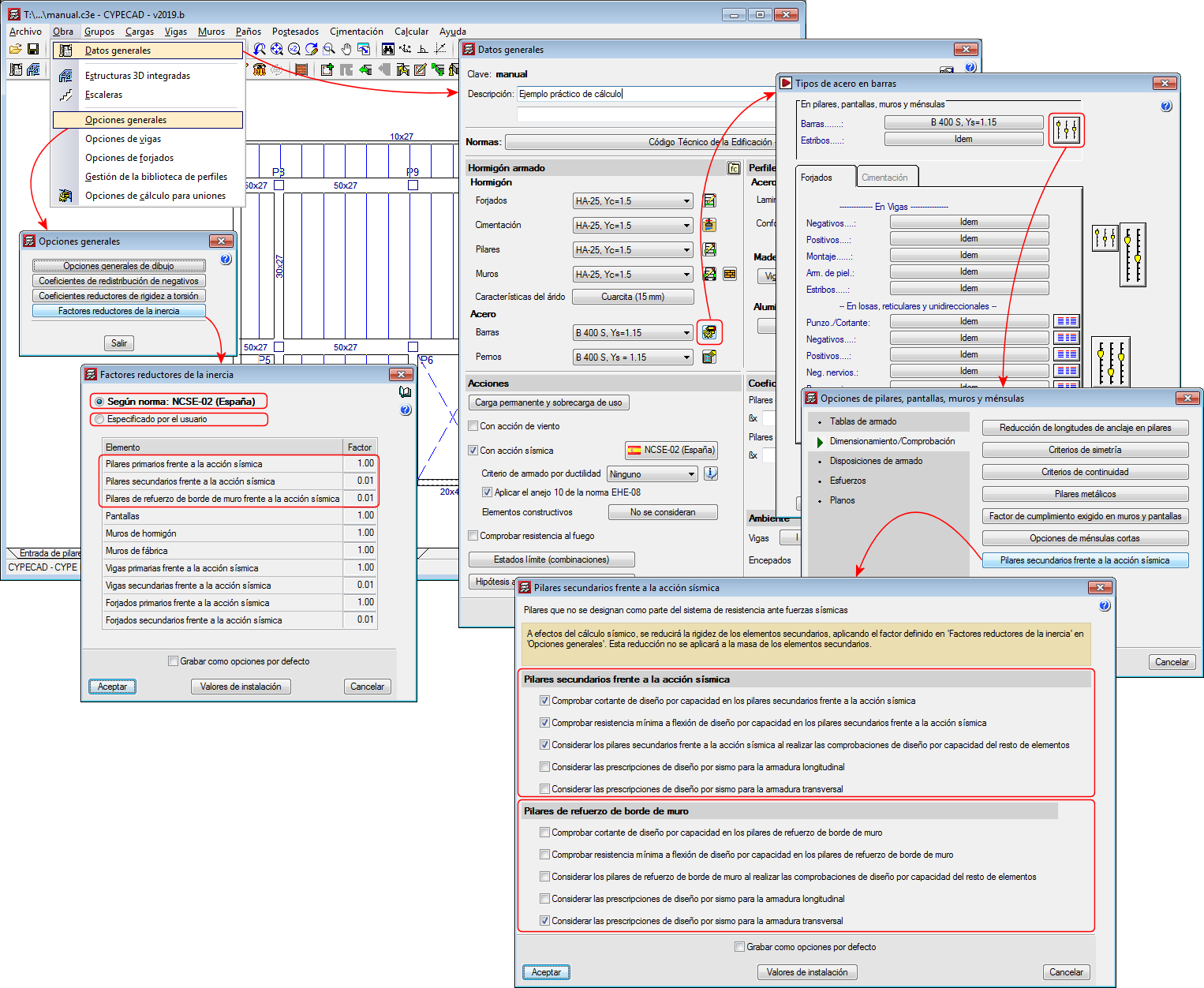
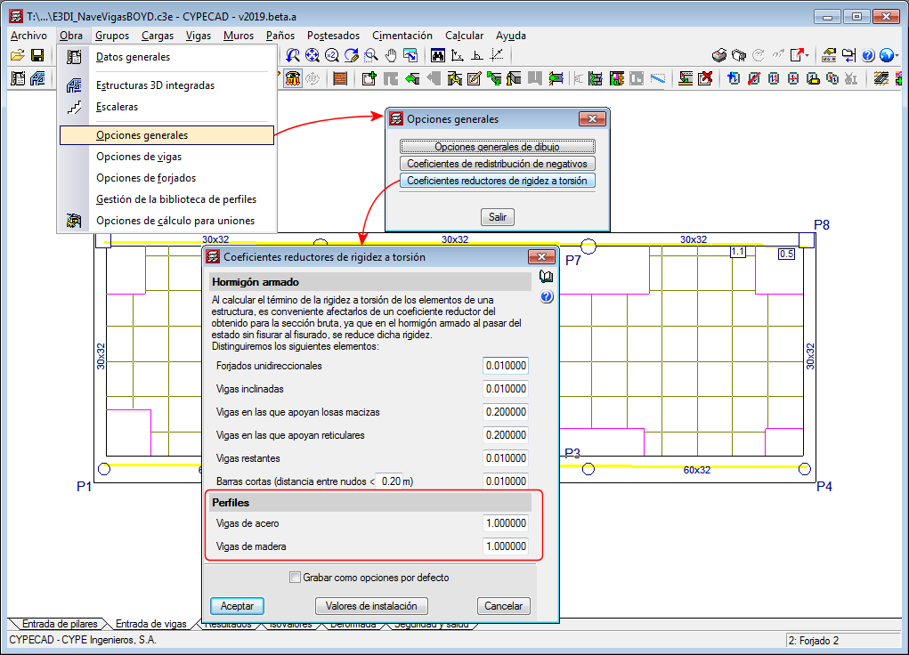
For the purposes of the seismic analysis, the stiffness of the secondary elements will be reduced by applying the factors defined in the "Inertia reduction factors" dialogue ("Project"> "General options" > "Inertia reduction factors”). This reduction will not be applied to the mass of the secondary elements.

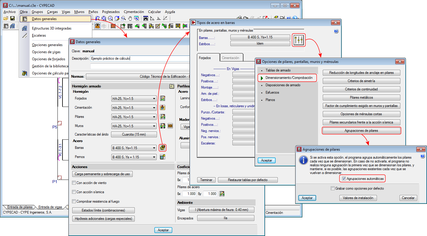
In terms of capacity design and seismic design requirements, the design and verification options defined in the “Secondary columns against seismic action” dialogue will be applied to the "secondary columns" and the "wall edge reinforcement columns" ("Project" menu> "General data"> "By position" button> "Options for columns, shear walls, walls and corbels”> "Design/ Code checks" section> "Secondary columns against seismic action" option).

The indicated inertia reduction factors and the capacity design options depend on the selected seismic code. Users, however, can define other reduction factors and select the capacity design options to apply.

For all these options to be active, users must have activated the seismic analysis with a seismic code that is compatible with the selected concrete code.

As of the 2019.a version, the Column schedule can be displayed showing the column groups defined in “Results” or ungrouped, in which case each column will be displayed in a column of the schedule.

Timber floor slabs can be assigned a null self-weight value.

The option “Update line loads of construction elements and post-tensioned tendons” has been implemented in the “Loads” menu in the “Beam Definition” tab.

As of previous versions, the program calculates the line loads of construction elements ( “Beam Definition” tab > "Loads" menu > "Construction elements" option) and post-tensioned tendons ("Beam Definition" tab > "Post-tensioned" menu). If changes were made in these elements or in others related to them that could affect self-weight values, the program did not recalculate the loads until the project was analysed or until drawings or reports were obtained.

As of the 2019.a version, when users select the new option: “Update the loads of construction elements and tendons”, recalculates the aforementioned loads, which allows users to view their values on-screen after the modifications have been made, without the need of having to analyse the project or print drawings or reports.

Since previous versions, torsional stiffness reduction coefficients can be defined for concrete beams. As of the 2019.a version, it is also possible to reduce the torsional stiffness for steel beams and timber beams. These coefficients can be edited in the "Torsional stiffness reduction coefficients" dialogue (Project > General options > Torsional stiffness reduction coefficients).

The “Forms” menu, which could be accessed as of previous versions from the “Panels” drop-down menu in the “Beam Definition” tab, is also available in the “Slab/Waffle slabs” drop-down menu in the “Results tab”.

The “Columns, shear walls and walls” and “Floors/Groups” menus in the “Column Definition” tab opens as a floating window to access the options it contains more easily whilst users are working with them.

CYPE Mentor