Update history​​

CYPECAD

Normas Técnicas Complementarias. Diseño por Sismo (2017).

Implemented in CYPECAD and CYPE 3D.

Normas Técnicas Complementarias. Diseño por Viento (2017).

Implemented in CYPECAD.

Normas Técnicas Complementarias. Diseño y Construcción de Estructuras de Mampostería (2017).

Implemented in CYPECAD.

Normas Técnicas Complementarias. Diseño y Construcción de Estructuras de Concreto (2017).

Implemented in CYPECADCYPE 3D and StruBIM Deep Beams.

The following new types of cold-formed steel have been added for the EAE 2011 code (Spain) and Eurocodes 3 and 4 (EU):

  • DX 51 D+Z
  • DX 52 D+Z
  • DX 53 D+Z
  • HX 260 LAD
  • HX 300 LAD
  • HX 340 LAD
  • HX 380 LAD
  • HX 420 LAD

An option has been included where users can indicate whether or not frames with the same geometry and reinforcement should be grouped in frame drawings (Frame drawings > Configure > General options).

In previous versions, the program always grouped frames with the same geometry and reinforcement.

The behaviour of the program when opening projects, regarding the visibility of templates in DXF or DWG format, or those of the BIM model, has been modified. In previous versions, when projects were loaded, the visibility of all the templates assigned to the “Column Definition” and “Beam Definition” templates was maintained. As of the 2018.i version, when a project is opened, this visibility is deactivated.

The reason for this change is because projects containing visible templates take longer to open, the time required being greater the larger the templates are and the larger the number of visible templates that are present. With this new behaviour, projects are loaded more quickly. Users can easily activate or deactivate the templates (DXF, DWG or BIM model) assigned to each floor or at the “Column Definition” tab by pressing the F4 key.

Since the possibility of connecting to a BIM model from CYPECAD was implemented in the 2018.c version, the program could obtain two types of templates from the BIM model:

  • The DXF or DWG templates associated with the BIM model. Furthermore, when a BIM project is launched from IFC Builder, users can automatically export a template in DXF format with the outline of each floor.
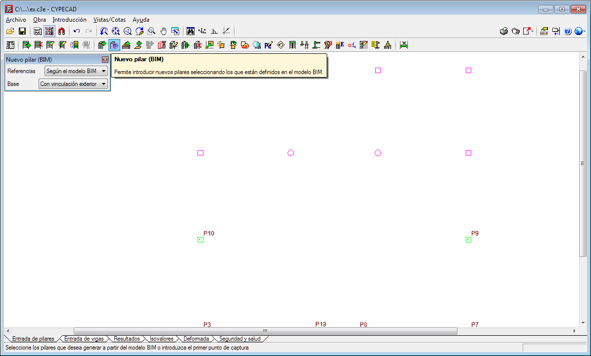
  • The templates of the “BIM model” that display the outlines of the floor slabs and outlines of the columns. These are updated when the BIM model is updated if the initial model has any changes.

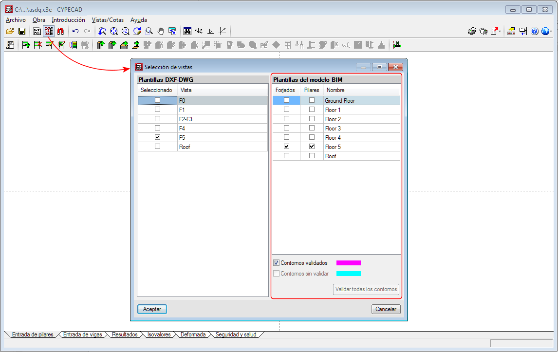
The views of the DXF/DWG templates (including those IFC Builder may generate in the BIM model) can be managed from the “View selection” dialogue box.

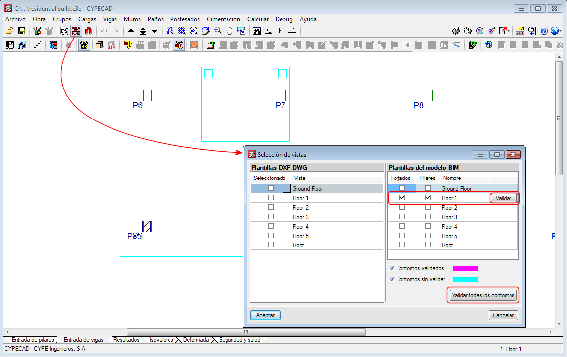
As of the 2018.i version, another section appears in the same dialogue box in which users can also manage the templates of the BIM model. The templates of the BIM model will be shown in magenta when they are generated for the first time (validated outlines). When the BIM model is updated, new outlines or outlines that have undergone any changes will be displayed in cyan (Outlines not validated). In the “View selection” dialogue box, users can mark “Outlines not validated” outlines of the BIM model (cyan) as “Validated outlines” (magenta).

With this improvement, the outlines before the update can be clearly distinguished from the new outlines and so graphically appreciate the changes the architectural model has undergone.

Generating the columns of the BIM model

The 2018.i version of CYPECAD includes the automatic generation of concrete columns based on the columns of the BIM model. The program will generate a rectangular or circular concrete column of the same size and at the same position for each column that has been defined in the BIM model.

To do so, the assistant that is activated when a project is created from a BIM model, contains the new stage “Columns”. In this stage, users can select the columns that are to be generated depending on their material. The assistant generates the columns with the same reference they have in the BIM model or with an automatic reference. In this stage, users can also select the type of support (with or without external fixity) columns starting at the first level will have. Columns starting on higher floors will be generated without external fixity.

The fixed point of the column will also be generated in accordance with the fixed point of the column of the BIM model.

Updating the columns of the BIM model

When users decide to update the BIM model with the changes the architectural model may contain, any columns that have been generated previously will not be modified. Neither will their position be changed nor will they be deleted nor new columns added, even though these changes have occurred in the BIM model. What is updated is the template of the BIM model and it is up to users to decide what to do when a column has been moved, deleted or introduced, as this affects intersections with the beams, columns and floor slabs that have already been introduced in CYPECAD.

In the previous version (2018.h), the way CYPECAD acts when a column is added or an existing column is moved was modified. As of this version, CYPECAD does not automatically recreate column-beam intersections and users can choose to recreate the intersections manually or have the program recreate them automatically for a floor using the “Reload group” option.

New column (BIM)

To be able to introduce a column that interprets another column of the BIM model that was not present when the connection of the CYPECAD project to the BIM model was launched (after the first import), the tool, “New column (BIM)” has been implemented. When this option is selected, the outlines of all the columns of the BIM model will appear. Then, if we click on one of these outlines, a column will be generated with the same dimensions as the column of the BIM model on each floor.

Users must bear in mind that including a new column may interfere with beams that are already present in floors of the CYPECAD project. Nonetheless, how the program behaves, regarding the automatic adjustment of beams, when a new column is introduced or an existing one is moved, was modified in the previous version of CYPECAD (2018.h). As of that version, the program does not automatically recreate column-beam intersections. Users can recreate them manually or use the “Reload group” option (“Beam Definition” tab > “Groups” menu) to recreate them automatically in the current floor group.

Code of Practice for Design Loads (other than earthquake) for Buildings and Structures. Part 3 - Wind Loads.

Implemented in CYPECAD.

The behaviour of the program has been modified when columns are introduced in a position where beams are already present in the floors they go through or when existing columns are moved to new positions where they would come into contact with beams. For these cases, and in previous versions, the program automatically recreated the new beam-column intersections.

As of the 2018.h version, these intersections are not recreated automatically and users can choose to:

  • Recreate the intersections manually
  • Recreate the intersections automatically using the new option “Reload group” (Beam Definition tab > Groups menu). This new option executes the same process that the program used to execute automatically in previous versions.

Long texts that appear in project report tables are adjusted so the width of the cell in which they appear does not increase substantially.