Long texts that appear in project report tables are adjusted so the width of the cell in which they appear does not increase substantially.


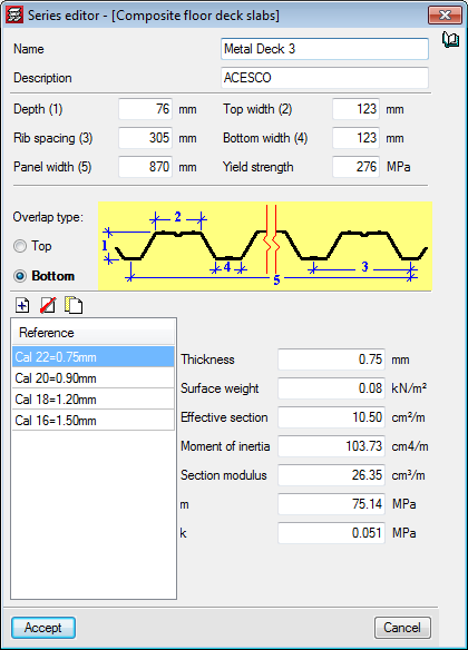
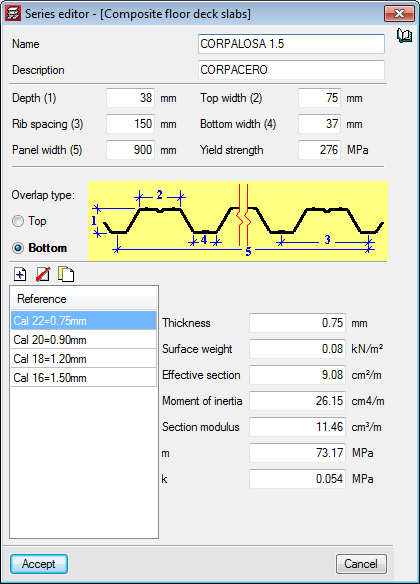
Composite deck slabs from the manufacturers: ACESCO and CORPACERO
Composite deck slabs from the Columbian manufacturers: ACESCO (Metaldeck 2” and 3”) and CORPACERO (CORPALOSA 1,5”, 2” and 3”) have been added to the program’s libraries.

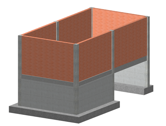
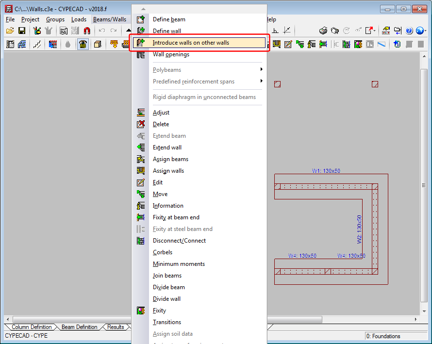
Introduction of walls on other walls
The 2018.f version allows users to introduce a wall on an already existing wall. To do so, the option “Introduce walls on other walls” (“Beam definition” tab > “Beams/Walls”). This way, users can analyse projects containing reinforced concrete walls on lower floors with masonry walls that start on them.
The program does not allow for reinforced concrete walls to be introduced on masonry or concrete block walls.
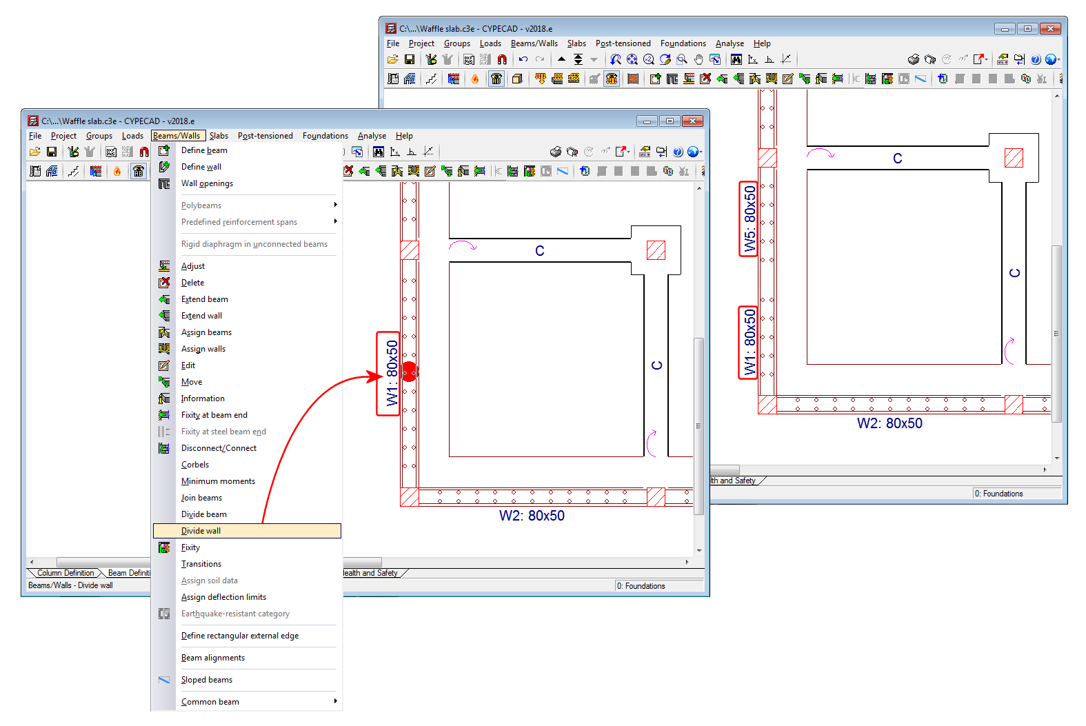
Divide wall
A tool has been implemented to divide walls. When a wall is divided, each part of the wall becomes a new wall with its own reference and properties.
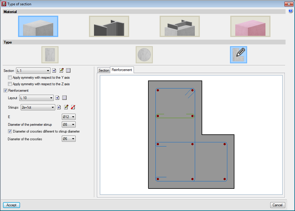
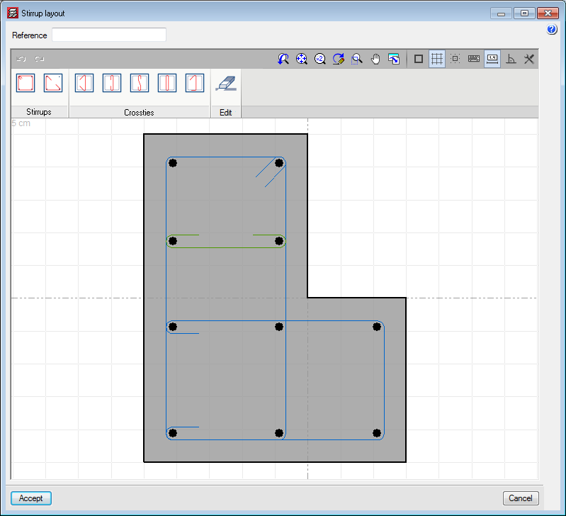
Stirrups in concrete columns with generic sections
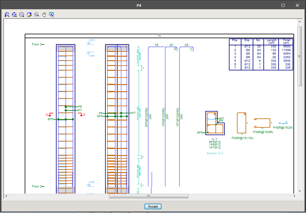
The option to define stirrups in generic section columns has been implemented. The stirrups that are defined are measured and detailed in reports and drawings. The program does not carry out a shear check on these type of columns.
Different stirrup layouts can be defined for each longitudinal reinforcement arrangement that has been defined for a section.
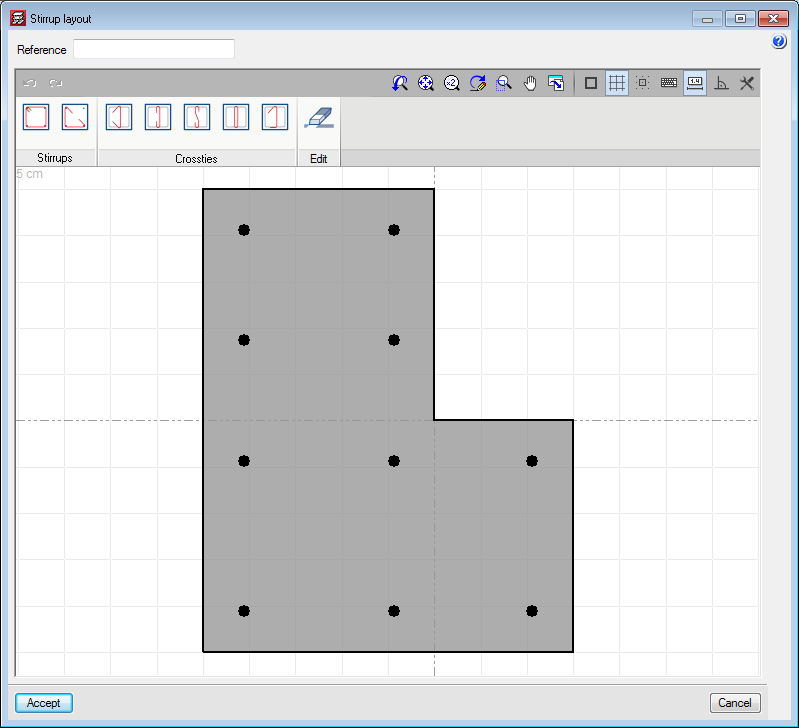
When a stirrup arrangement is added or edited, users access the stirrup layout editor which contains different tools to define the stirrups and crossties that join the longitudinal reinforcement bars.
Users can place closed stirrups, open stirrups and different types of crossties. Crossties can have a different diameter to that of the stirrups.
After selecting the type of stirrup or crosstie, users have to select the longitudinal bars to be joined and finish off by clicking on the right mouse button.
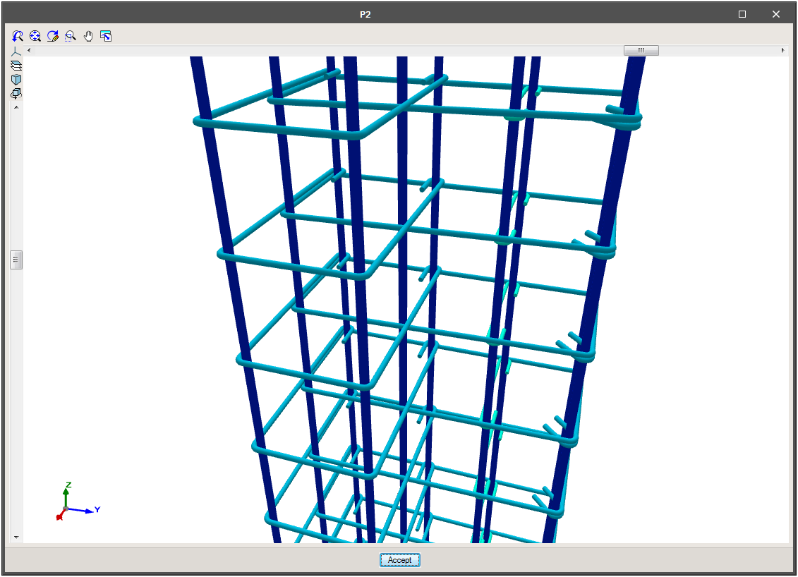
In “Results”, the spacing of the stirrups can be defined in the columns table, as well as the stirrup densification zones. Users can also view the details and consult the 3D view of the reinforcement.
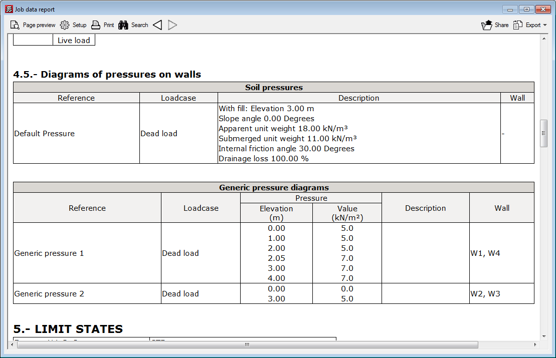
Pressures on walls
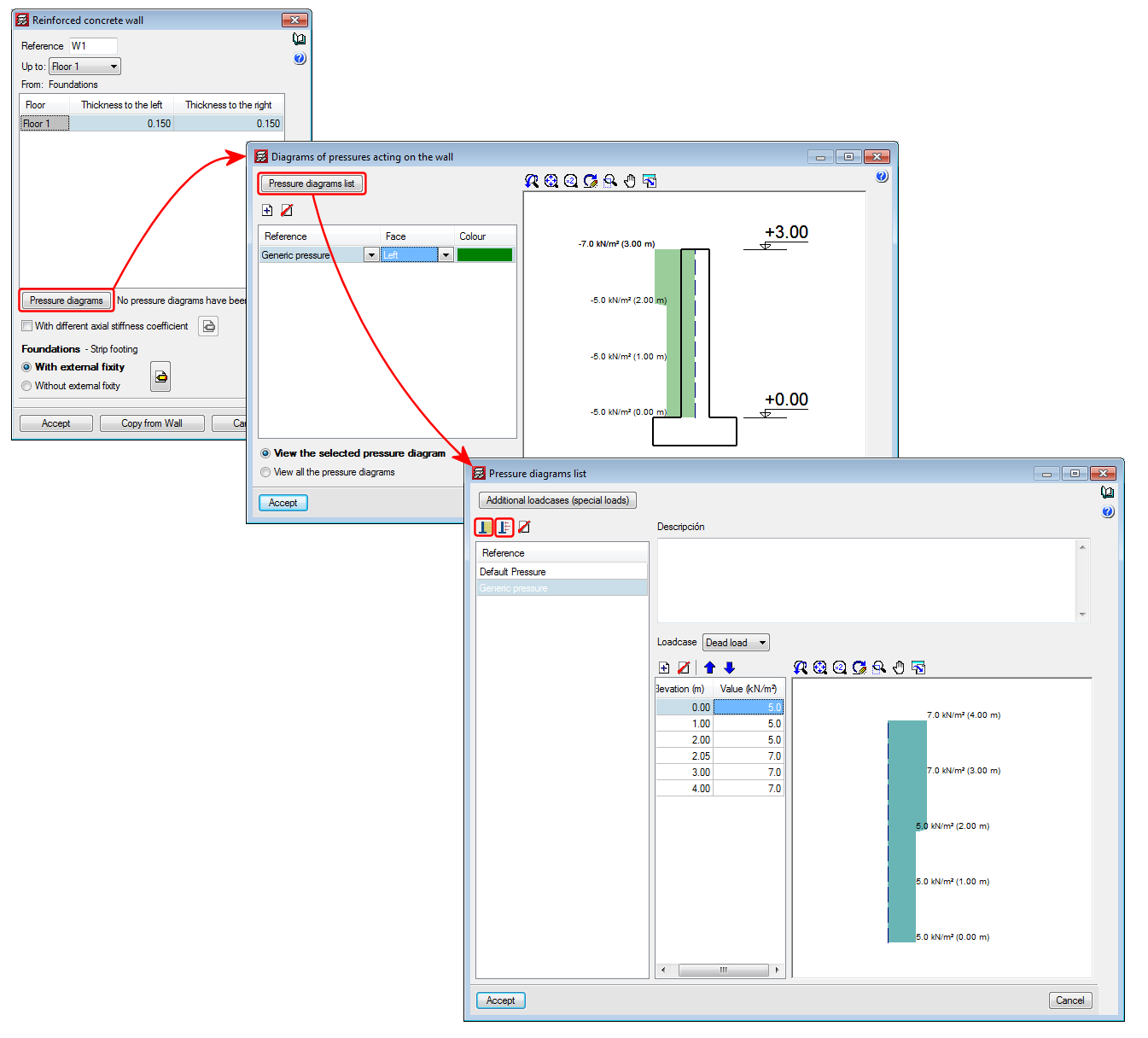
As of the 2018.e version of CYPECAD, pressures acting on walls can be defined. In previous versions, only soil pressures acting on walls could be introduced. With this improvement, as well as soil pressures, users can define a generic pressure diagram associated with any loadcase.
The Project data report includes the soil and generic pressures that have been defined in the project as well as the walls on which they act.
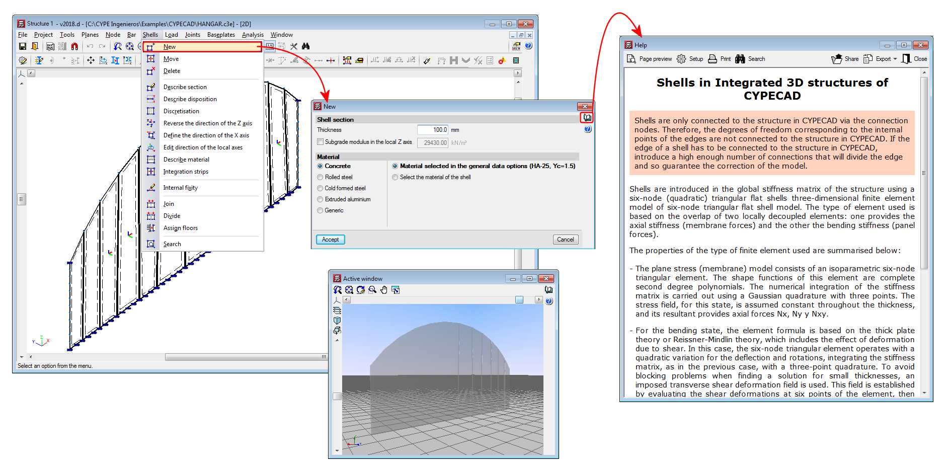
Shells in "Integrated 3D structures of CYPECAD"
As of previous versions, flat shells (flat two-dimensional elements with a constant thickness) were implemented in the force analyses of CYPE 3D for concrete, rolled steel, cold-formed steel, aluminium and generic materials. These shells, however, could not be imported in Integrated 3D structures of CYPECAD.
As of the 2018.d version, users can define flat shells in “Integrated 3D structures of CYPECAD” by introducing them in the application itself or by importing CYPE 3D structures that contain shells. The operating mode is the same as that for CYPE 3D. Users must bear in mind that the shells of the “Integrated 3D structures of CYPECAD” are conditioned by their connection to the CYPECAD structure: the shells are only connected to the CYPECAD structure via the connection nodes. Therefore, the degrees of freedom corresponding to the internal points of the edges are not connected to the CYPECAD structure. If the edge of a shell has to be connected to the CYPECAD structure, users must ensure to introduce a sufficient number of connections that will divide the edge and guarantee the correction of the model.