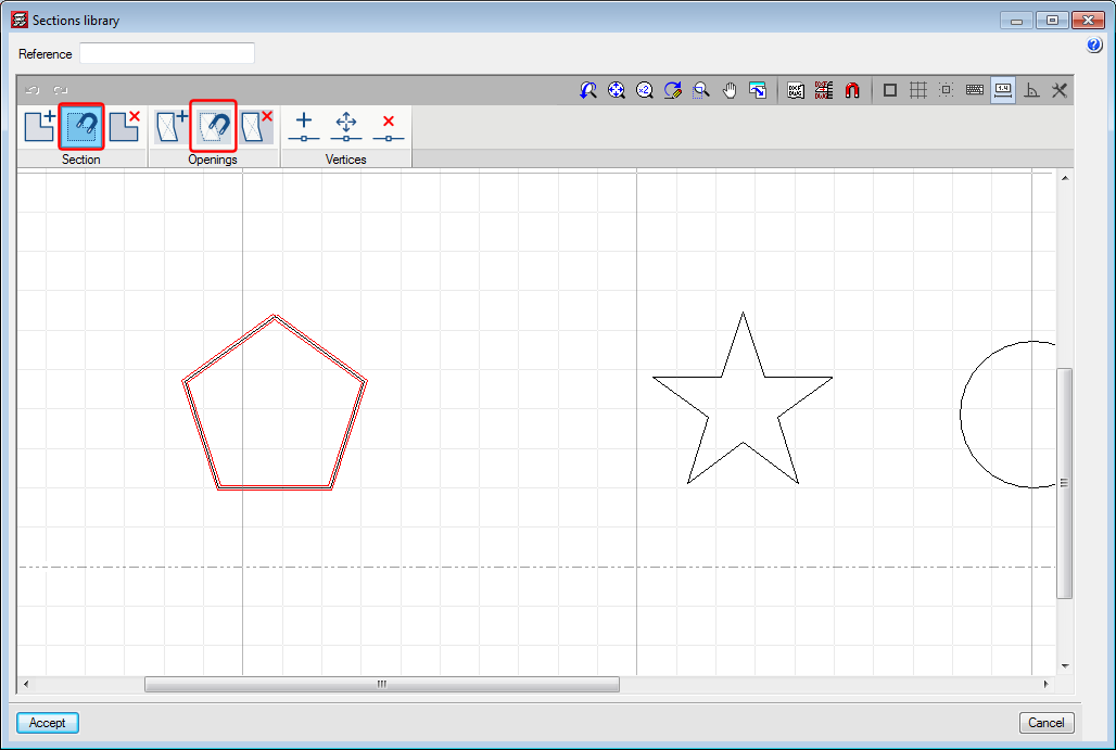
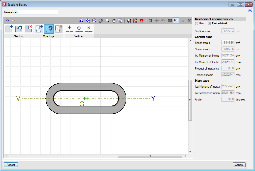
New tools have been implemented in the editor for columns with generic sections. One tool snaps to sections and the other snaps to openings of DXF or DWG templates. Both snap to closed polygons.


New tools have been implemented in the editor for columns with generic sections. One tool snaps to sections and the other snaps to openings of DXF or DWG templates. Both snap to closed polygons.
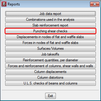
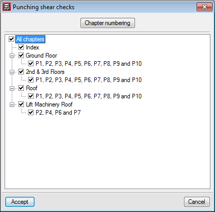
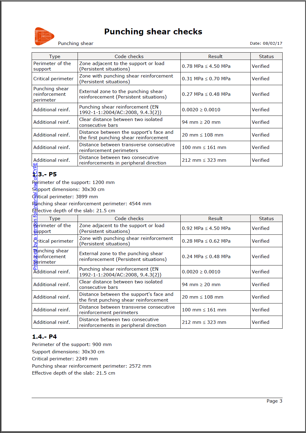
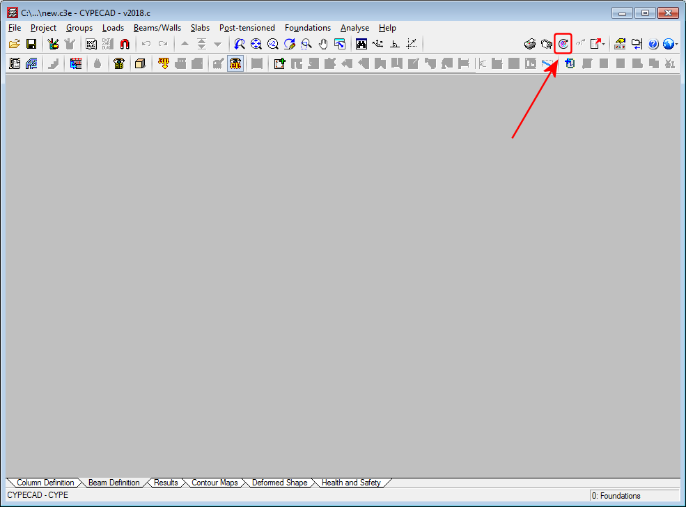
The report ‘Punching shear checks’ has been implemented. This report shows a summary of the punching shear checks that have been carried out for the selected columns.
As of the 2018.c version, it is possible to import a BIM model in a CYPECAD project that has already been started, and in which no new floors have been defined. This improvement allows for links to be created with empty projects where the options in ‘General data’ have been previously configured.
The ‘Import’ button will appear as active in the ‘Beam Definition’ tab when no floors have been created in the project.
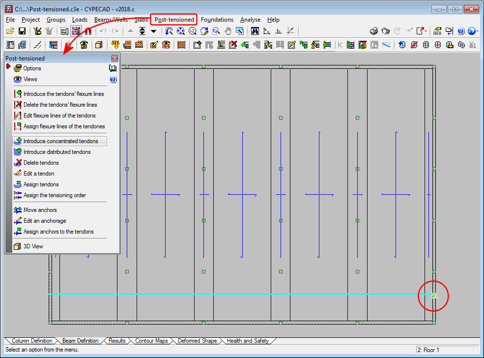
New snap points have been implemented in the introduction of post-tensioned tendon ends. In previous versions, when a tendon was introduced that crossed one or more panels, it was only possible to snap to the edges of the external beams. With this improvement, intersections with internal beams of the floor slab can be snapped to.
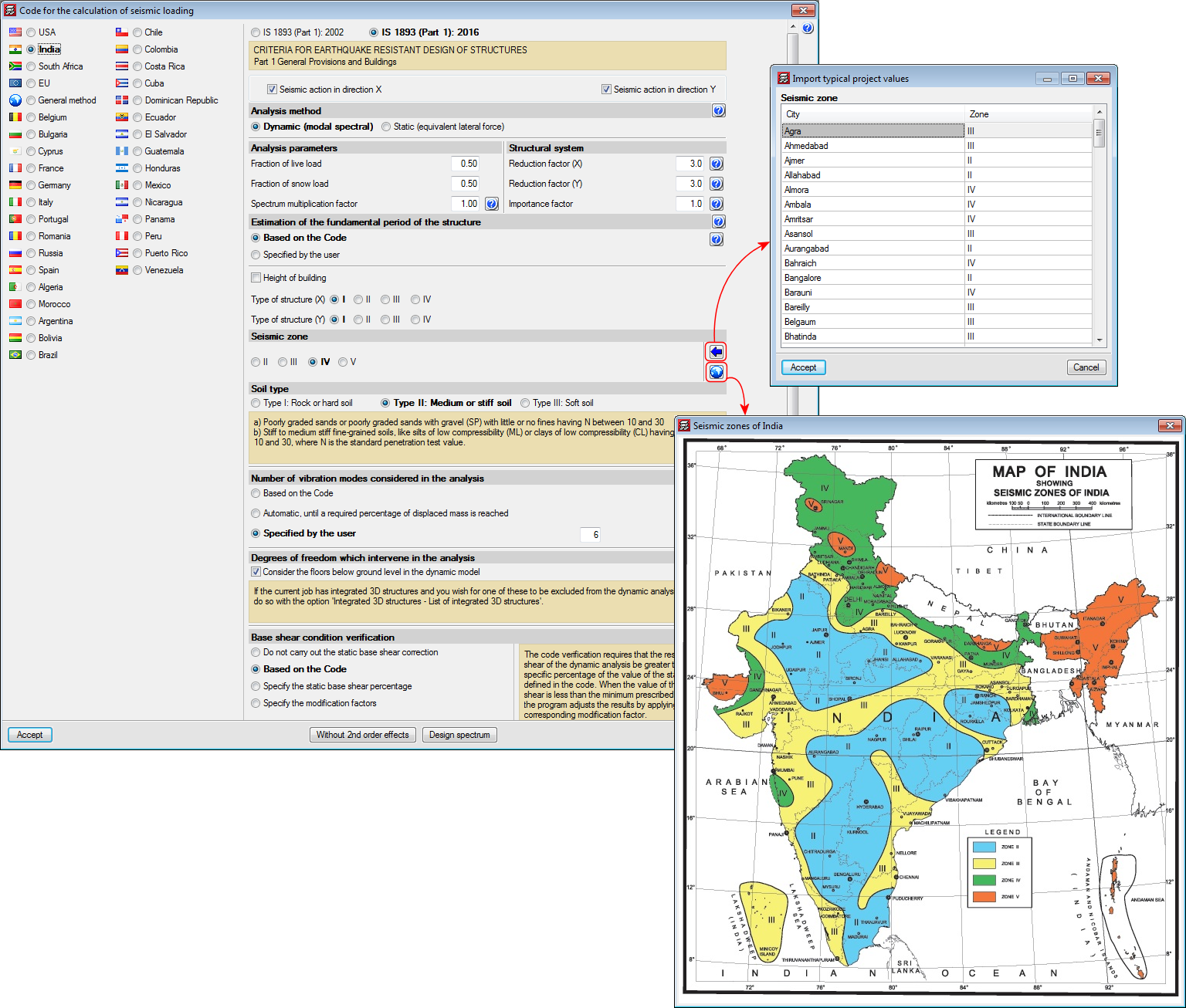
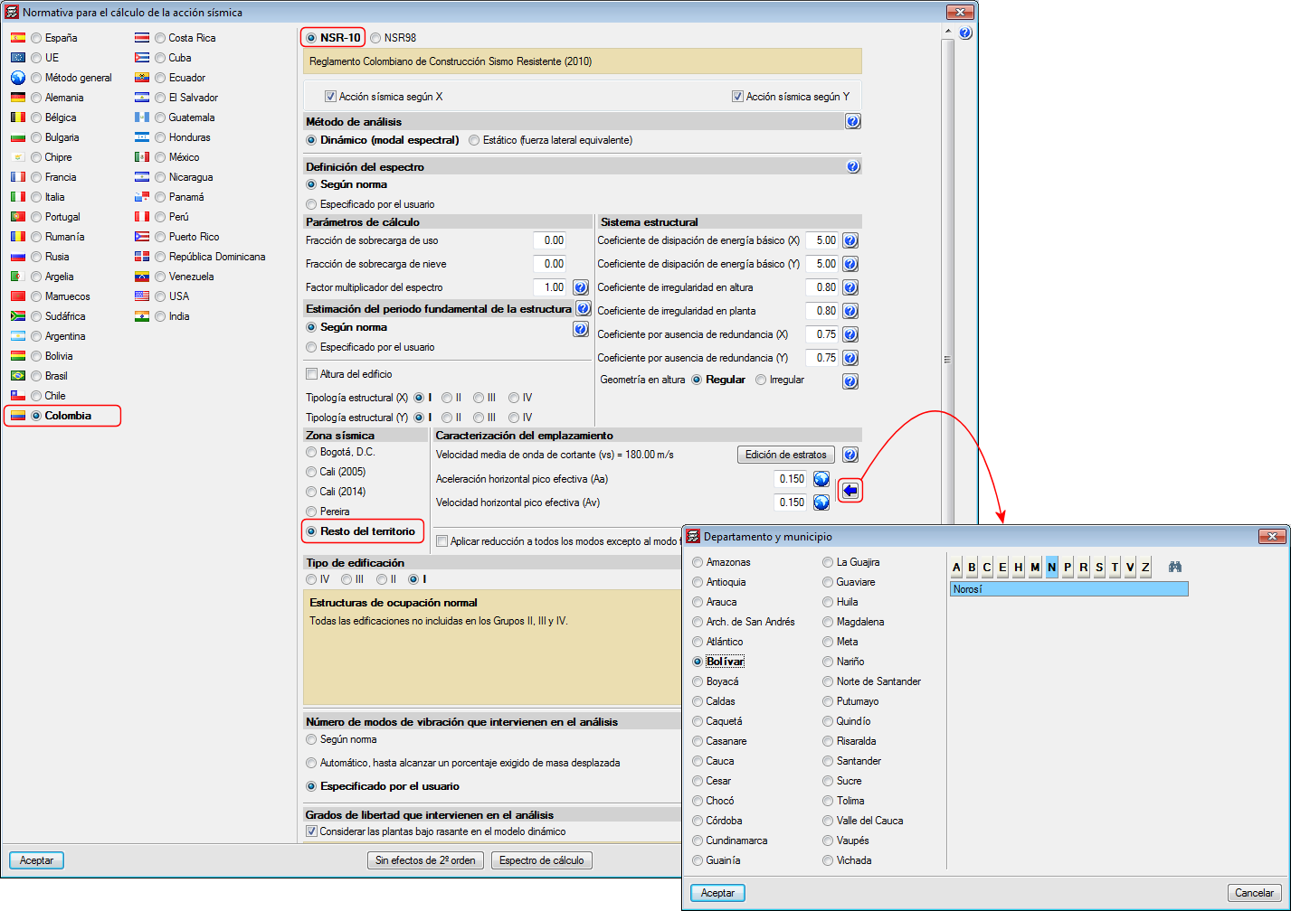
Decree 945 of 5 June 2017 published by the Ministry of Housing, City and Territory of the Republic of Columbia partially modifies the “Reglamento Colombiano de Construcción Sismo Resistente NSR-10”.
In the 2018.c version of CYPE programs, the changes indicated in this decree, which affect CYPECAD and CYPE 3D, have been implemented. These changes allow users to select certain municipalities that were previously omitted in the NSR-10 Regulation.
The municipalities that have been added are: Norosí (Bolívar), Guachené (Cauca), San José de Uré (Córdoba), Tuchín (Córdoba), Nariño (Nariño) and Coveñas (Sucre).
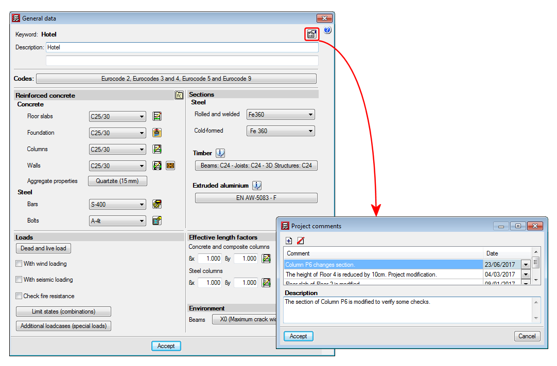
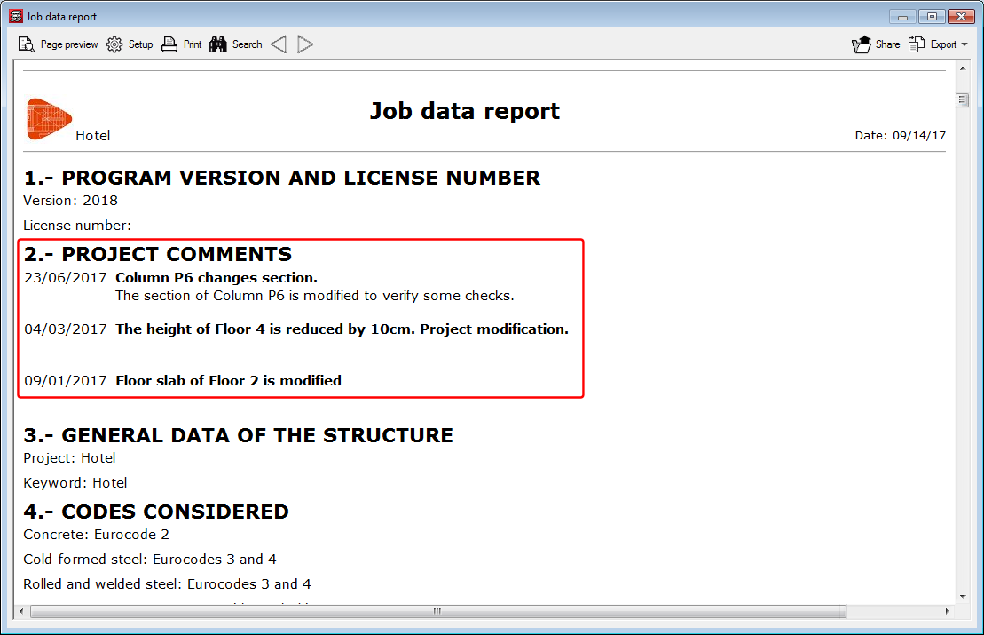
A tool has been implemented which allows users to add a history of comments to a project. These comments are added and managed in the “General data” dialogue box. All these comments can be displayed in the “Job data” report. This improvement allows users to manage a useful history of comments, changes, modifications or revisions carried out on the project.
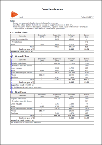
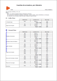
The “Job take-off report” has been improved and a new type of report: “Reinforcement quantities, per diameter” has been added.
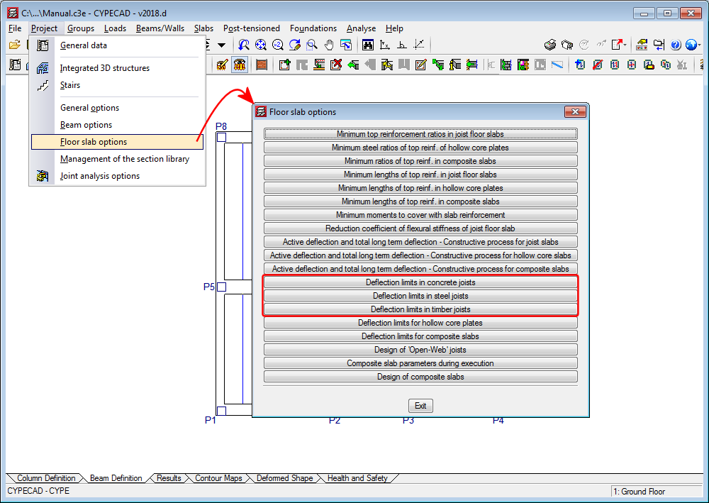
The option: “Deflection limits in joists” has been divided into three to establish different deflection limits for concrete, steel and timber joists.
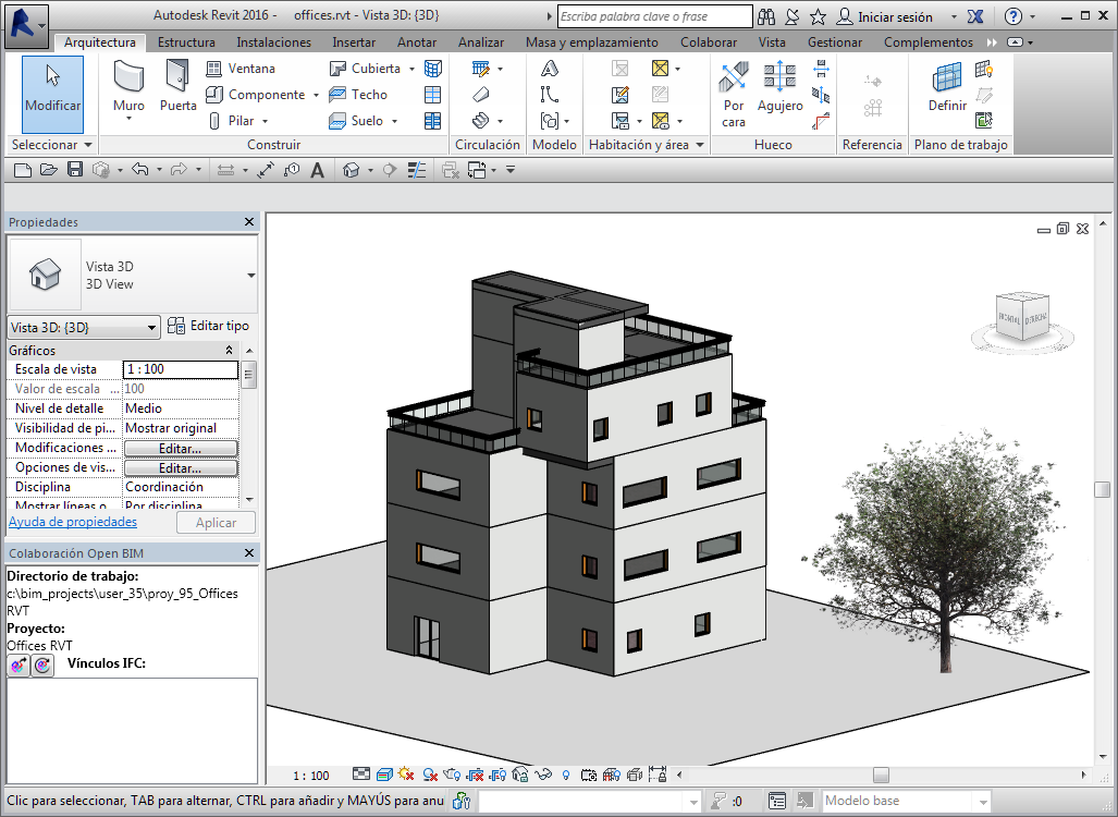
As of the 2018.a version, CYPECAD projects which have been started based on a BIM model can read and import walls and partitions of the BIM model as construction elements. Non-structural walls and partitions provide stiffness to the structure during an earthquake by modifying the distribution and magnitude of the forces due to the seismic action. More information on how non-structural elements interact with the structural elements against seismic action, and which properties are to be taken into account to consider their influence in the behaviour of the structure against seismic action, can be found on the Interaction of the structure with the construction elements webpage.
With this improvement, the construction elements of CYPECAD will be synchronised with the walls and partitions of the BIM model. They will be automatically introduced, if users select for them to be imported and will be updated if any changes arise in the architectonic model.
As well as providing stiffness to the structure, they will generate line loads on the floor slabs or beams on which they bear. These loads, which are laborious to introduce and modify, if any changes arise, with the 2018.a version, can be placed automatically at the position where the wall is located in the BIM model.
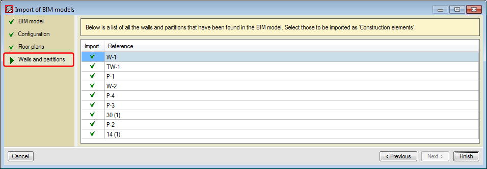
During the creation of the CYPECAD project based on a BIM model or during the update of the BIM model, a new section appears in the wizard that will list the different types of walls and partitions, so to offer users the option of whether or not they are to be imported.
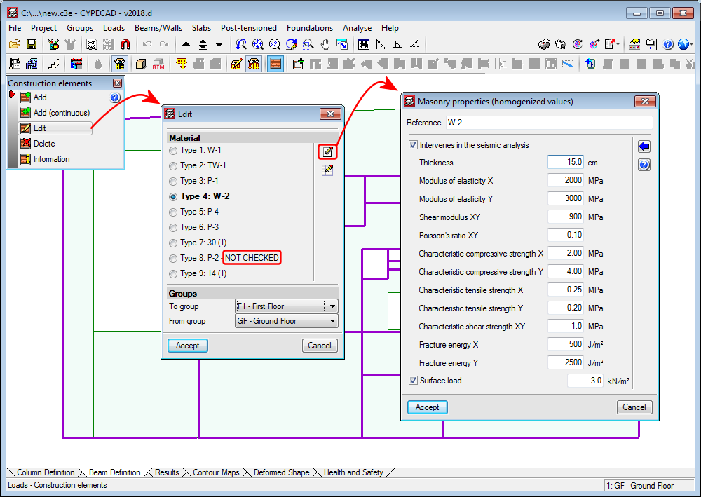
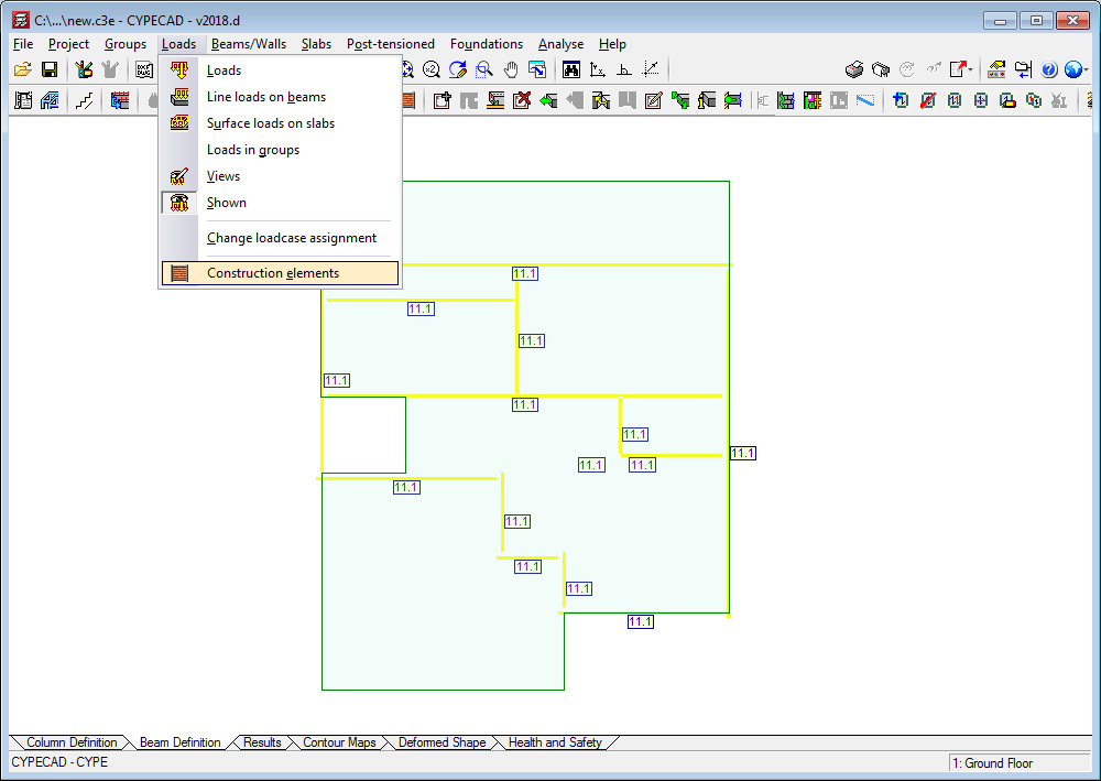
From the “Loads > Construction elements” menu, users can edit, consult and check the walls and partitions that have been imported.
Each type that is imported is defined as “NOT CHECKED”, and it is the user who will decide how the walls will affect the structure: whether they intervene in the seismic analysis and/or if loads on the floor slabs are to be generated.
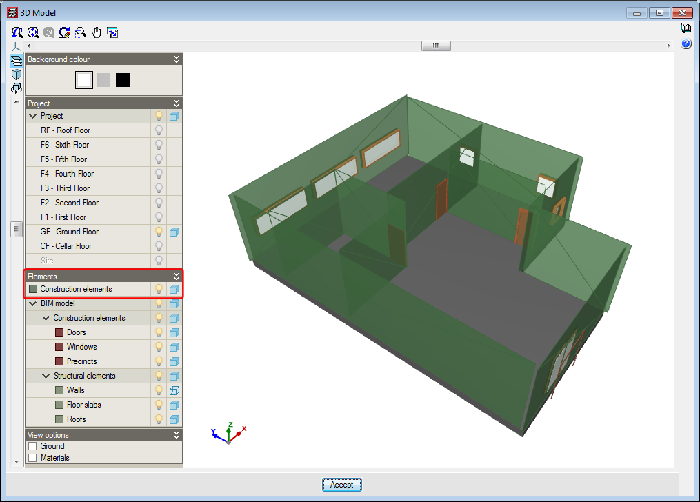
Construction elements are shown in a specific layer in the 3D view, which helps users to distinguish the non-structural walls that are present in the architectonic model and have been taken into account in the analysis of the structure.
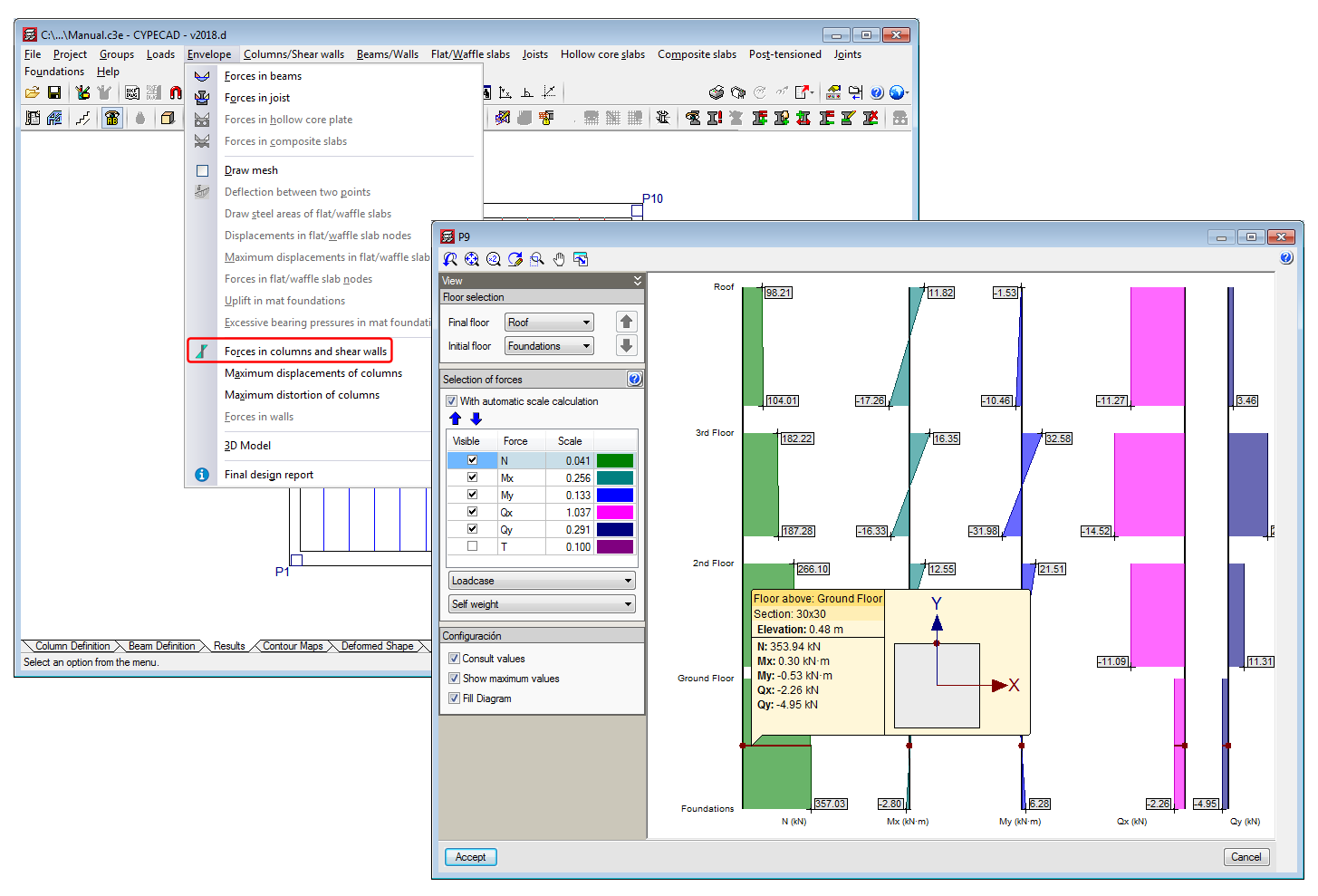
The force consultation panel for columns and shear walls has been improved. From the “Envelopes” menu in the “Results” tab, users can access the new force consultation panel. It can also be accessed from the “Column schedule”.
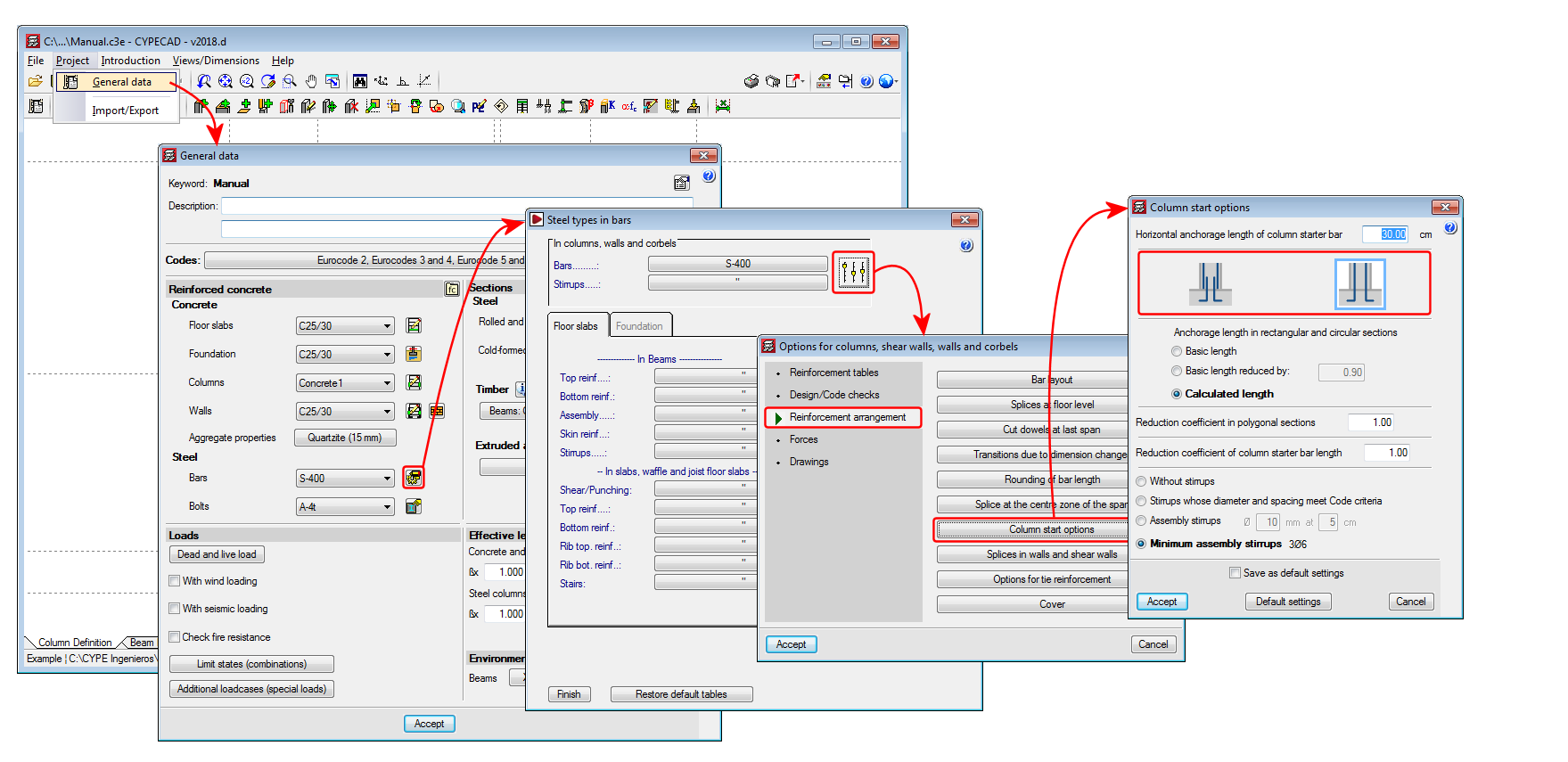
An option has been added that allows users to select whether or not to overlap reinforcement at column starts at the foundations (“Column Definition” tab or “Beam Definition” tab > Project > General data > “By position” button > “Steel types in bars” dialogue box, “Columns, shear walls, walls and corbels” button > “Reinforcement arrangement” section, “Column start options” button).
When the reinforcement overlaps are placed half-way at the floor, this option allows users to not carry out the overlap with the starts at the foundation.