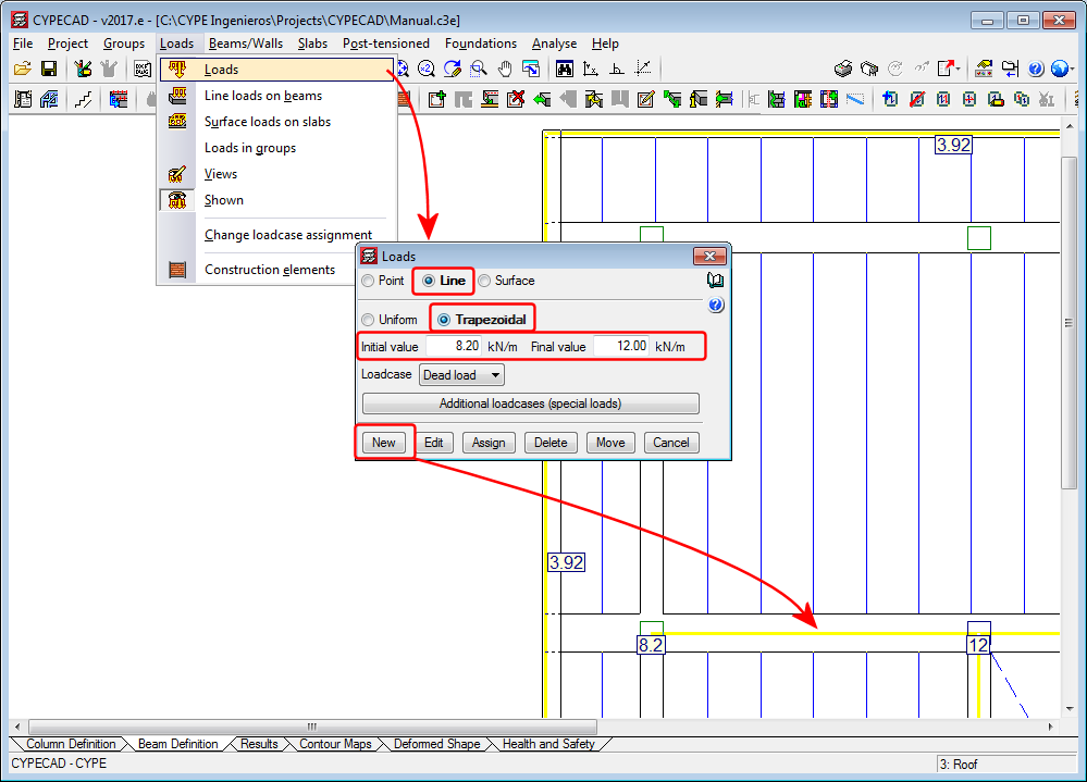
Linear trapezoidal load
As of the 2017.e version, CYPECAD allows users to define linear trapezoidal loads.
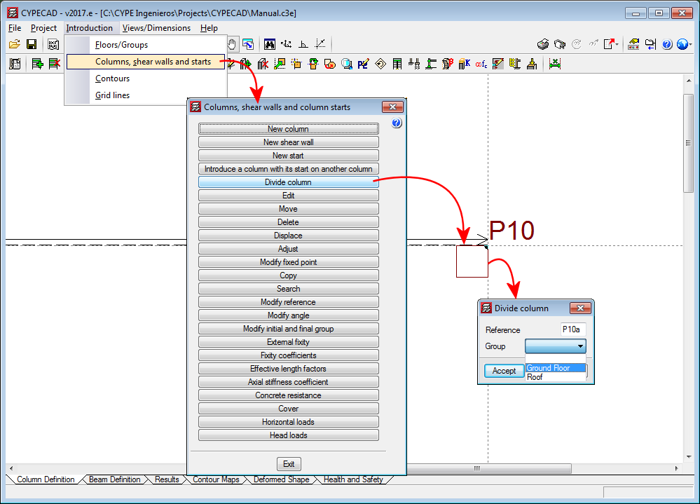
Divide column
The option, “Divide column”, which divides a column into two parts has been implemented in the “Columns, shear walls and starts” menu (Column Definition tab > Introduction). The option divides columns in such a way that the start of the column above is the top of the one below.
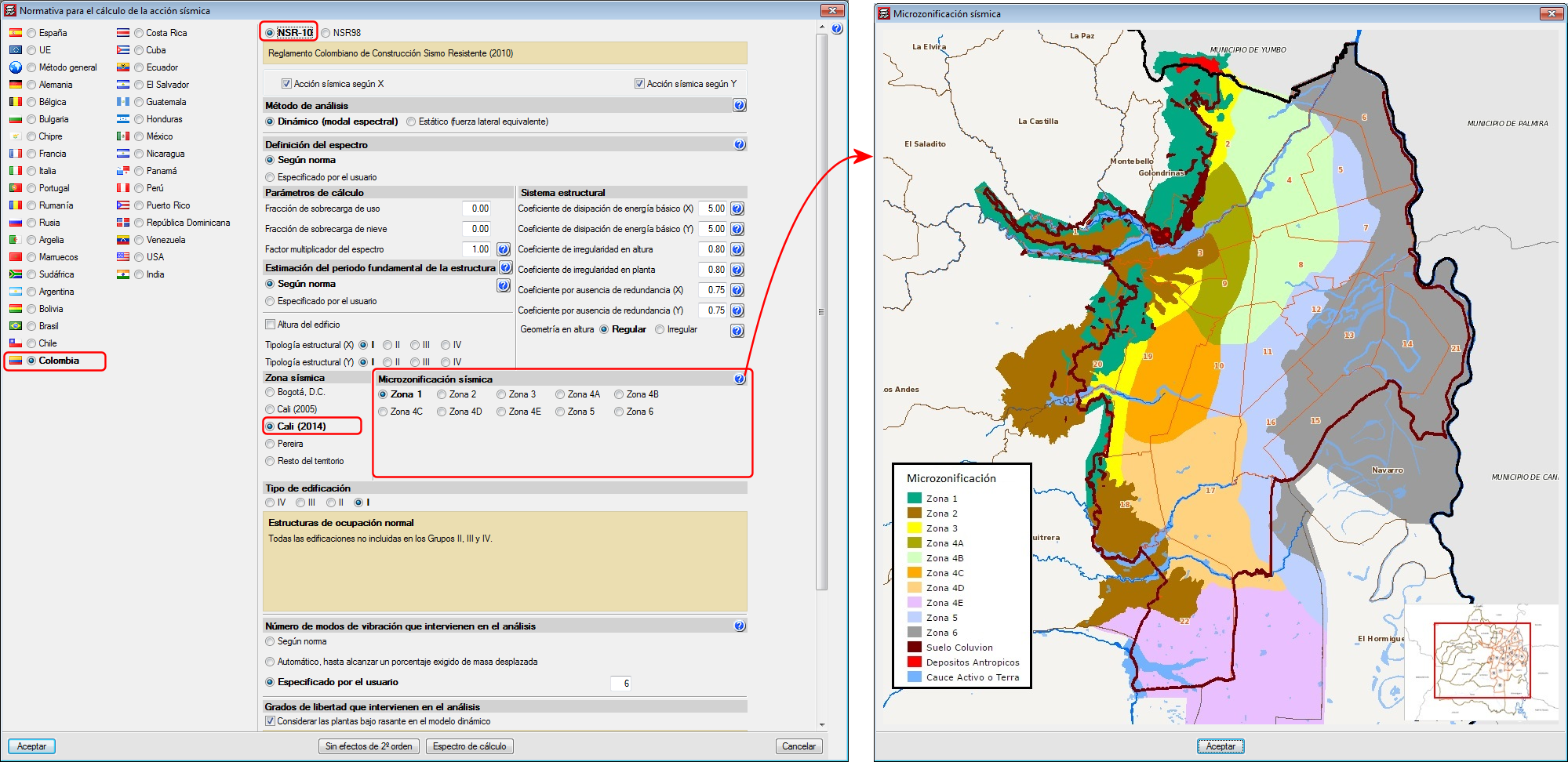
Code implementation improvements. Microzonificación de Cali (Decreto 411.0.20.0158 de 2014)
As of previous versions, when users selected to carry out a seismic analysis with the NSR-10 code (Colombia), they could choose amongst several microzonations:
- Bogotá D.C.
- Cali (2005)
- Pereira
As of the 2017.e version, the Microzonation of Cali of 2014 has been included (Decree 411.0.20.0158 of 2014).
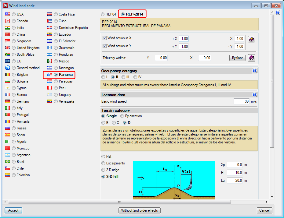
Code implementation. REP-2014 (Panamá)
REP-2014 . Reglamento Estructural de Panamá.
Implemented in CYPECAD.
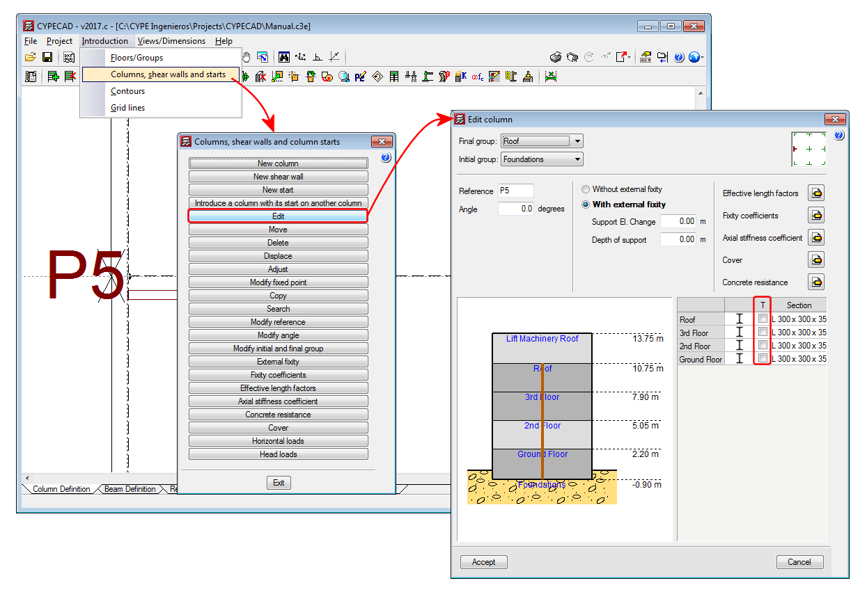
Transposed steel columns
An option has been implemented in CYPECAD whereby users can rotate the section of a selected steel column by 90° about its centre of mass, during the introduction or editing process. This operation does not take into account the fixed position of the column. A column marked “T” appears next to the selected section type, which when marked “transposes” the position of the column in the indicated span.
The operation carried out to transpose a column does not usually provide the same results as applying a rotation of 90°. A 90° rotation is applied to all the spans (floors) of the columns and about the selected fixed point. By transposing the column section, however, the column rotates 90° about the centre of gravity of the section and only the selected column spans rotate. Therefore, the choice as to which option to use will depend on what users wish to do.