Update history​​

CYPECAD

As of the 2017.a version, CYPECAD allows users to assign an earthquake resistance category to concrete beams (primary or secondary), in such a way that those selected as being secondary beams are not considered as being part of the structural system that has to resist seismic action. The stiffness of these beams is reduced in the analysis and the checks carried out on them are different compared to those carried out on beams considered to be primary beams. More information can be found in the section:  "Earthquake resistance category” in the new features of the 2017.a version.

As of the 2017.c version, the earthquake resistance category of floor slabs is implemented, which allows users to class the following types of concrete floor slabs as primary or secondary:

  • Flat slabs (reinforced and post-tensioned)
  • Waffle slabs
  • Hollow core slabs
  • Concrete joist floor slabs (generic, precast reinforced, prestressed reinforced, or in situ joists)

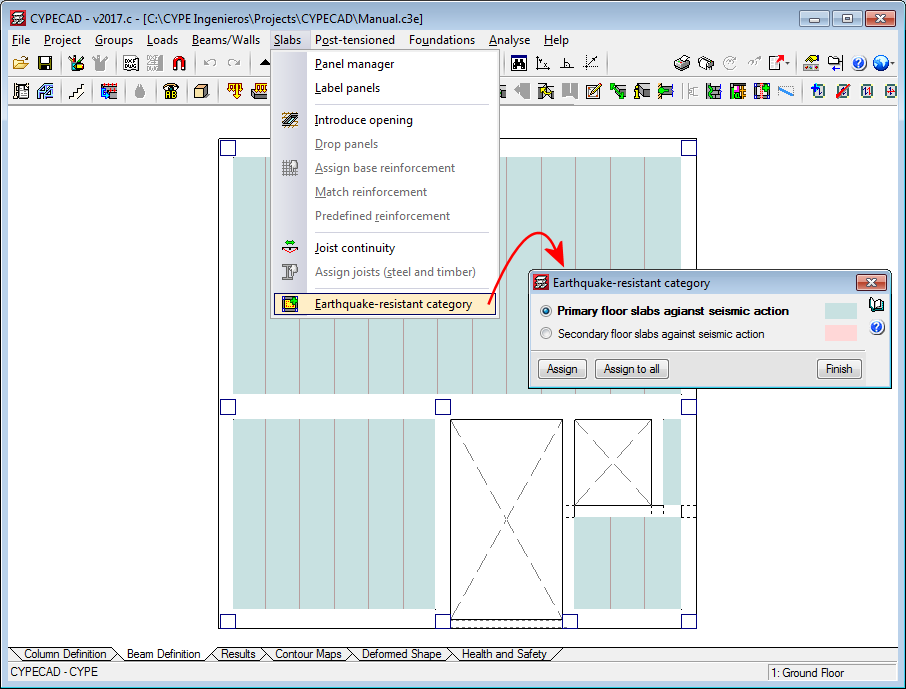
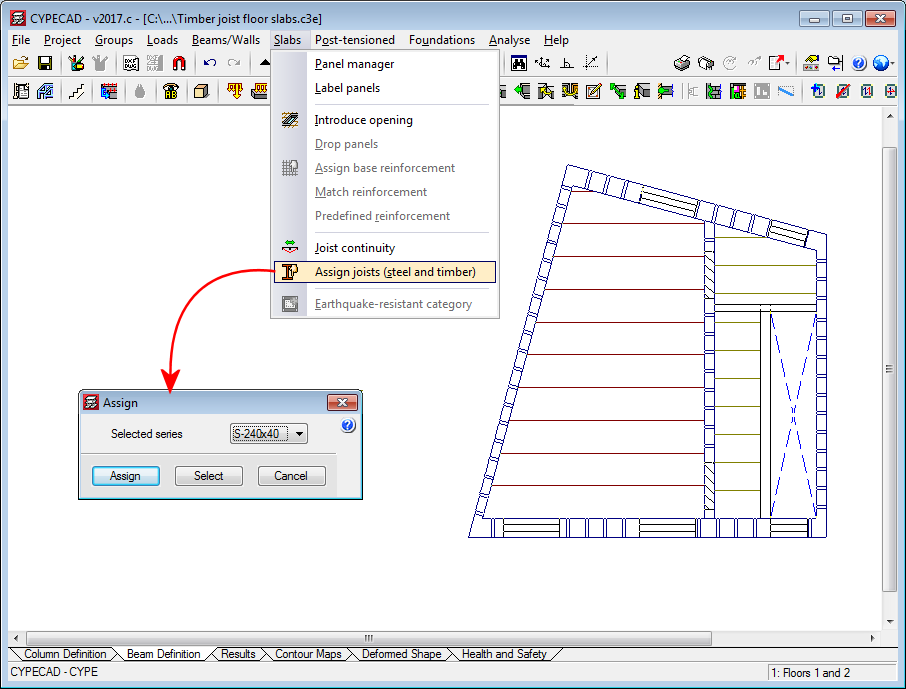
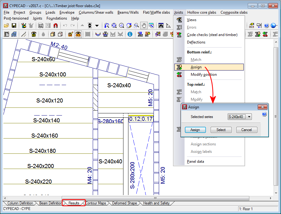
In the “Earthquake resistant category” dialogue box (“Beam definition” tab > “Slabs” menu > “Earthquake resistant category”), users can assign this category to concrete slabs. By default, any slab that is introduced has assigned the “Primary slab against seismic action” category.

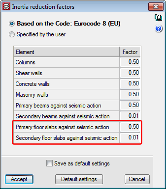
Just as for concrete beams, concrete floor slabs which are assigned as being secondary are not considered to be part of the earthquake-resistant structural system. To do so, CYPECAD reduces the stiffness in the analysis of these elements in a ratio, that can be edited, which by default is 0.01. Users have two options to indicate the inertia reduction factors that are to be used in the analysis. These are located in the “Inertia reduction factors” dialogue box (“Beam definition tab” > “Project” > “General options” > “Inertia reduction factors”) and are “Based on the code” (default option) and “Specified by the user”.

As of the 2017.c version, users can introduce, check and design caissons for the following concrete codes:

  • CIRSOC 201-2005 (Argentina)
  • ACI 318M-08 (USA)
  • ACI 318M-11 (USA)
  • NCh 430 Of 2008. D° 60:2011 (Chile)
  • NTCRC:2004 (Mexico)
  • NSR-10 (Colombia)
  • NTE E.060:2009 (Peru)

As of previous versions, users could already introduce, check and design caissons (Tubulões) for the following Brazilian concrete codes:

  • ABNT NBR 6118:2007
  • ABNT NBR 6118:2014

When caissons are designed in CYPECAD with the Brazilian design codes, the quantities exported to Arquimedes include those of the “Tubulões”.

The program displays on-screen and provides reports of the checks that have been carried out for the aforementioned codes.

As of the 2017.c version of CYPECAD, before launching the analysis, a section of the series used to define the steel or timber joist floor slabs can be assigned to the panel. This way, when the first analysis of the structure is launched, the stiffness of the section used in the analysis is that of the assigned section and not the stiffness of the smallest section of the series.

To do so, the option: “Assign joists (steel and timber)” has been implemented (“Beam definition” tab > “Slabs” menu).

It is also possible to assign the section when a floor slab is introduced or edited. To do so the option: “Initial section”, has been implemented in the new and editing joist floor slabs menus for steel and timber joists.

Once the project has been analysed, the section that is obtained in the design process will be the one assigned to the floor slab and therefore, its stiffness will be the one contemplated if a new analysis of the structure is launched.

Users must bear in mind that when the structure has been analysed, and as long as no modifications are carried out which eliminate the design results, the “Assign joists (steel and timber)” option will not be active in the “Slabs” menu in the “Column definition” tab. In this case, joists can be assigned in the “Results” tab using the “Assign” option in the “Joists” menu, where users can also check the results if the section of the joist is changed.

Introduction

As of the 2017.c version, CYPECAD becomes part of the group of programs that are integrated in the CYPE Open BIM workflow. Projects can be created and linked to a BIM project by means of IFC files which store the information of the architectonic model of the building.

CYPECAD is integrated in the proposed workflow by using the architectonic model as an updatable template to introduce the structural model, analyse and design it.

When a projected is linked, all the IFC files that are present in the BIM project directory are read. The structural model created in CYPECAD can be viewed in the 3D view of the BIM model, as well as the consolidated BIM model (all the IFC files making up the BIM project: HVAC installations, radiating floor circuits,...).

The structural model that is introduced in CYPECAD can be exported in IFC format to complement the BIM model. Once it has been exported, the other applications that are integrated in the workflow can update the BIM model and view the structural model of the building (consolidation of the BIM model).

Projects linked to a BIM model

In the 2017.c version of CYPECAD, the following elements of the architectonic model are imported and updated to easily introduce the structural model:

  • Floors
    In the CYPECAD model, each floor is linked to the equivalent floor of the architectonic model. Nonetheless, elevation differences can be defined with respect to the elevation of the floor, for example, to deduct the thickness of the non-structural flooring. Floor modifications in the BIM model, such as elevation changes, creation of new floors or deletion of existing floors, can be updated automatically.

  • Columns
    The outlines of the columns that have been defined in the architectonic model can be seen in the Column Definition tab. When columns are introduced, the outlines of these architectonic columns are snapped to and a fixed point is proposed. When a column is introduced on an outline that is not present on all the floors of the BIM model, the program proposes it be placed only on the floors where it is present.
  • Floor slab outlines of the architectonic model
    The floor slab outlines defined in the architectonic model can be represented in the Column Definition and Beam Definition tabs. The outlines can be activated or deactivated using the menu option: Groups > Display the floor slabs of the architectonic model (BIM model). The outlines work as a drawing template to introduce beams more easily.
  • 3D view of the BIM model
    As well as the 3D view of the structure, the option to see the 3D view of the BIM model has been added. The view can be accessed by clicking on the  icon from the toolbar or from the Groups menu.

Updating the BIM model 

To update the BIM model, the IFC files contained in the directory of the BIM project have to be read. Any changes that have been carried out on the architectonic model can update elements of the analysis model of CYPECAD (floors, floor slab outlines and column outlines). The additional IFC files update the 3D view of the BIM model.

The updating process carried out in CYPECAD due to modifications that have been carried out in the architectonic model, can be configured by activating or deactivating the following actions:

  • New elements
    • Include new elements of the BIM model in the analysis model: New floors or new column or floor slab outlines are added.
  • Modified elements
    • Update the elements of the design model that have been modified in the BIM model
    • Update the analysis elements even if they have been modified
    • Recover elements deleted in the analysis model
  • Deleted elements
    • Delete the elements of the analysis model that have been deleted in the BIM model
    • Delete the elements of the analysis model even if they have been modified

Export in IFC format 

The structural model defined in CYPECAD can be exported in IFC format to the directory of the BIM model. The different elements making up the structure are exported: columns, beams, joists, forms, footings, pile caps, flat slabs, waffle slab forms, post-tensioned tendons, integrated 3D structures, stairs...

National Annex to CYS EN 1998-1:2004. Eurocode 8: Design of structures for earthquake resistance. Part 1: General rules, seismic actions and rules for buildings.

Implemented in CYPECAD and CYPE 3D.

National Annex to CYS EN 1991-1-4:2005. Eurocode 1: Actions. Part 1-4: General actions – Wind actions.

Implemented in CYPECAD.

As of the 2017.b version, CYPECAD allows users to different types of concrete for the following elements:

  • Floor slabs
    For floor slabs, the type of concrete can be different for each floor group.
  • Stairs
  • Integrated 3D structures
  • Sloped beams

Manual de Diseño de Obras Civiles por Sismo México 2015.

Implemented in CYPECAD and CYPE 3D.

With the 2017.a version, shaded force diagrams of beams and joists can be displayed (with a different colour depending on the type of force). To do so, a new option “Draw the diagrams with infill” has been included in the “Forces in beams” and “Forces in joist” dialogue boxes (Results > Envelopes > “Forces in beams” or “Forces in joist”).

In the 2017.a version, users can select the frames of each group to be represented in the “Frames drawing”. To do so, an option: “Selection in groups” has been implemented in the “Frames drawing” configuration dialogue (File > Drawings > Add or edit the “Frames drawing”). Upon selecting this option, a button is displayed indicating the number of selected frames that are going to be represented in the drawing (which by default , are all the frames of the project). By pressing this button, a dialogue box appears where users can select which frames from which floors are to be shown on the drawings.

In the 2017.a version of CYPECAD, users can introduce a partial fixity coefficient at the end of a concrete beam. To do so, the option: “Fixity at beam end” (Beam Definition tab > “Beams/Walls”) has been implemented, which opens a dialogue box in which users can indicate that the beam end is:

  • Fixed (default option)
  • Pinned
  • Partially fixed
    Users can introduce a numerical value between “0” (pinned) and “1” (fixed).

When this option is selected, symbols are drawn, in a different colours and shapes, at the ends of the beams to indicate which option has been applied.

In previous versions, beam ends could be pinned or fixed using the “Pin/Disconnect” option which is also used to disconnect columns from wall-support type beams. Now this option is only used to disconnect columns and is now called “Disconnect/Connect”.

In the seismic analysis of the structure, CYPECAD can design structural beams as primary or secondary beams, depending on their role in the earthquake-resistant structure (Beam Definition > Beams/Walls > Secondary beams). Secondary beams are not considered as being part of the structural system to resist seismic loads hence, these elements do not need to be designed specifically for that.

The stiffness of the secondary beams, for seismic loadcases, is reduced depending on the value defined in the “Inertia reduction factors” dialogue box (“Project” > “General options”). The mass of the secondary beams is taken into account.

As for the capacity checks, users can indicate how the secondary beams are to be considered depending on their judgement. The following options can be activated in the “Secondary beams against seismic action” dialogue box (“Project” > “General data” > “Design options for steel bars” > “Beam options” “Design/Code check”):

  • Check capacity design in secondary beams against seismic action.
  • Consider secondary beams against seismic action when carrying out the capacity design checks of the remaining elements.
  • Consider seismic design prescriptions for longitudinal reinforcement quantities and stirrup spacing.