CYPE Mentor

Update history​​

CYPECAD

New assembly reinforcement and skin reinforcement design options have been implemented and can be used in jobs for which the concrete and seismic (if applicable) codes allow for the use of the advanced beam editor. 

Assembly reinforcement design options

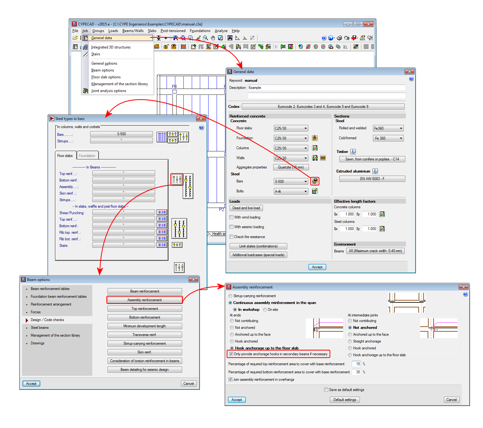
A new option “Only provide anchorage hooks in secondary beams if necessary” has been implemented. This option is active by default, and so has the same effect as in previous versions. If the option is deactivated, the assembly reinforcement hook will always be provided at secondary beams.

Skin reinforcement design options

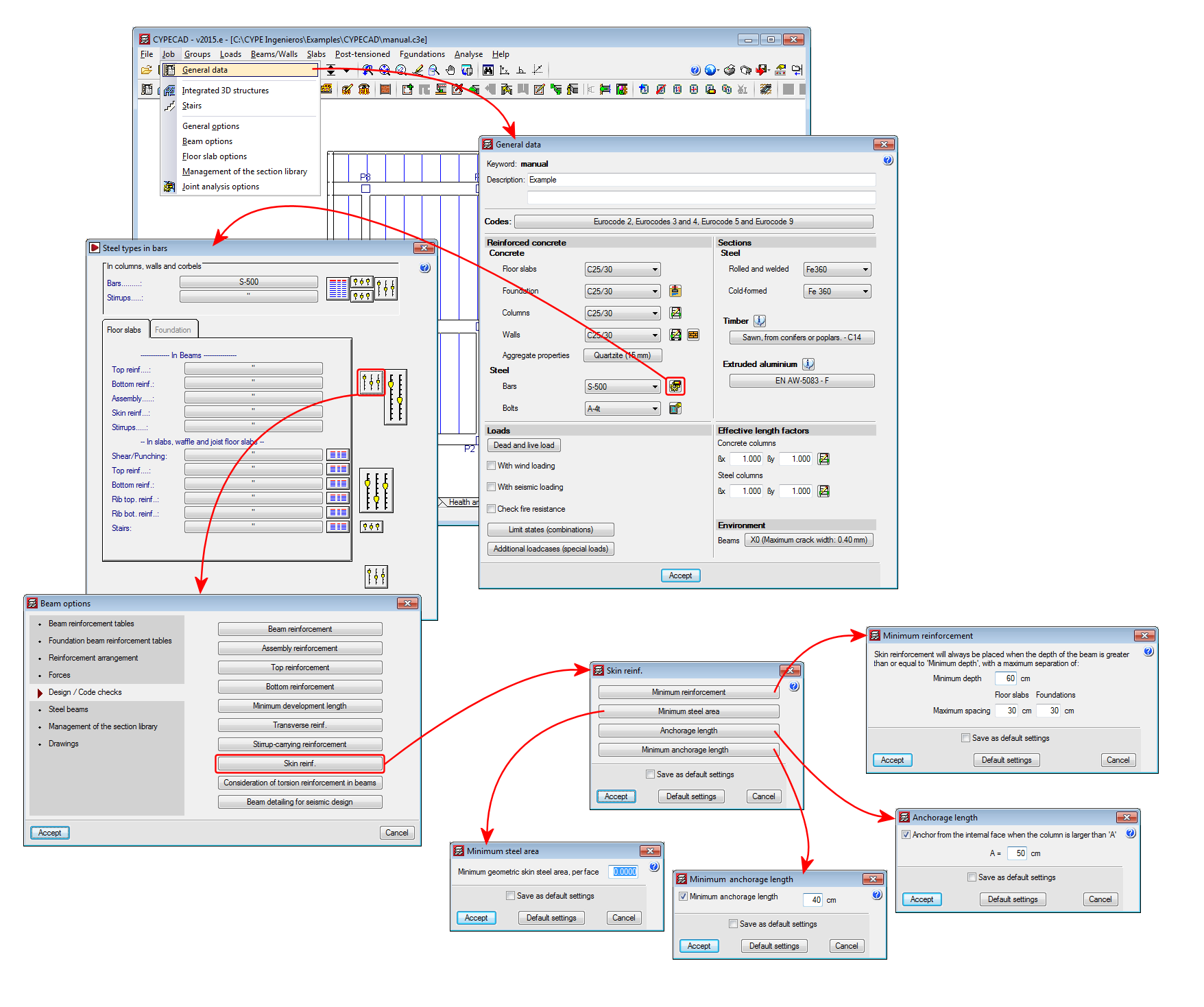
A series of design options for skin reinforcement have been implemented. In previous versions, users could only indicate as of which beam depth the skin reinforcement was to be placed, and once placed, the maximum spacing it was to have for floor slabs and beams in floor slabs and foundations had to be defined. Now these options can be edited by selecting the “Minimum reinforcement” button (skin reinforcement dialogue box – see image). Additionally, three new options have been implemented:

  • Minimum steel area
    Allows users to specify the minimum skin steel area at each side of the beam. If the steel area indicated by the design code is greater than that indicated in the option, the program will apply the greatest value.
  • Anchorage length
    Allows users to anchor skin reinforcement as of the internal face of the column where the dimension of the column in that direction is greater than a user specified value . For other cases, the skin reinforcement will be anchored as of the column axis. This option avoids having to provide excessive anchorage lengths in wide columns.
  • Minimum anchorage length
    Allows users to indicate the minimum anchorage length for the skin reinforcement. The program will check the minimum length indicated by the code and will apply the greater of the two.

Frame drawing improvements

The frame drawings in the advanced beam editor have been improved when the option to draw larger bars further away has been activated.

Norma Chilena Oficial Diseño Sísmico de Edificions (Includes modifications of decree n° 61 (V. and U.) of 2011).

This code was already implemented in previous CYPECAD and CYPE 3D versions. Now, with the 2015.e version, a user seismic spectrum can be defined. A design spectrum must be defined to carry out the seismic analysis of the structure. Each seismic resistance code provides the criteria that are to be followed within a specific territory for the seismic action to be considered in the project. Nonetheless, the project designer can adopt, under his/her responsibility, different criteria to that established in the code. The program offers different ways to proceed for the use of either way. The design seismic spectrum can be:

  • Calculated in accordance with that specified in the seismic code to be applied.
  • Specified by users based on his/her criteria.

Diseño estructural. Cargas de viento.

Implemented in CYPECAD.

  • BAEL-91 (R-99) (France)
    Fascicule n°62 – Titre I- Section I Règles techniques de conception et de calcul des ouvrages et des constructions en béton armé suivant la méthode des états limites – BAEL 91 révisé 99.
  • NTCRC:2004 (Mexico)
    Normas técnicas complementarias del reglamento de construcciones para el Distrito Federal

These codes were already implemented in CYPECAD, CYPE 3D and other CYPE programs as of previous versions. Now, in the 2015.e version, these codes are implemented in “Punching shear verification” and hence, also in the punching shear check carried out by CYPECAD in accordance with code criteria. This check was implemented in CYPECAD in the 2015.a version and, since then, coexists with the tangential stress check.

Complete and trim punching shear perimeter

Two options have been implemented which allow users to modify the punching shear perimeter calculated by the program (Results > Flat/Waffle slabs > Punching shear):

  • Complete perimeter

    Allows users to draw the punching shear perimeter on zones at which it has been trimmed by the analysis or manually.
  • Trim perimeter

    Allows users to trim the punching shear perimeter of a column.

Users can use the “Regenerate perimeters” option (Results > Flat/Waffle slabs > Punching shear) to eliminate any modifications carried out on the punching shear perimeters.

Punching shear check at supports with adjacent dropped beams

The option “Supports to which dropped beams reach” has been implemented (Job > General data > By position button > Slab options > Punching shear) which does not allow the punching shear check to take place at a support if the ratio between the depth of the dropped beams adjacent to the support and the depth of the slab is greater than the value defined in this option. The default value for this ratio is 1.20.

Improvements of the codes indicated below have been implemented or included in the application. Detailed information can be found in the previous sections:

  • Concrete code
    • CIRSOC 201 2005 (Argentina) and IS 456: 20000 (India)
  • Code regarding loads on structures. Seismic loads
    • CIRSOC 103-2013 (Argentina)
    • CHOC-08 (Honduras)
    • NTC 1997 (Mexico – Guadalajara)
  • Fire safety. Fire resistance of the structure
    • ABNT NBR 15200:2012 (Brazil)

Projeto de estruturas de concreto en situação de incêndio.

Implemented in the “Fire resistance check” module and checks the fire resistance and designs the protective coatings for beams, floor slabs, columns, concrete shear walls and walls using the tabular method defined in this code.

With this code, the “Fire resistance check” module carries out the following checks and designs:

  • For the indicated structural elements for which a protective coating can be defined, the program designs the minimum thickness of the protective coating so that the requirements of the applied code are met.
  • For the indicated structural elements for which a protective coating can be defined, the program checks the element with the assigned fire resistance data.
  • If a coating is assigned to a structural element and the program verifies it is not needed to meet the requirements stated in the corresponding code, the program will indicate the coating of the structural element is not necessary, and so the minimum thickness of the coating will be applied for construction reasons.

Users must have the “Fire resistance check” module to be able to carry out these checks, as well as the corresponding aforementioned structural elements.

The fire resistance check in CYPECAD is activated in the “General data” dialogue box (Job > General data). Upon activating it, a dialogue box opens where users can define the required resistance, the compartmentation of the floors (with or without compartmentation) and the coatings of the construction elements. If users wish to use the “ABNT NBR 15200:2012” fire resistance code, the “ABNT NBR 6118:2014” or “ABNT NBR 6118:2007” concrete code must be selected in CYPECAD.

The corresponding Brazilian code required to carry out the fire resistance checks of steel beams and columns in CYPECAD and steel sections in CYPE 3D will be implemented in upcoming versions.

Normas Técnicas Complementarias para Diseño por Sismo para Guadalajara 1997.

Implemented in CYPECAD and CYPE 3D.

Código Hondureño de la Construcción. Normas Técnicas. Capítulo 1. Cargas y fuerzas estructurales. Diseño por Sismo

This code was already implemented in CYPECAD and CYPE 3D in previous versions. Now, with the 2015.d version, the new seismic map (which displays zones 3, 4 and 5) has been implemented and values between 0.10 and 0.60 can be introduced for the “Factor de zona sísmica” (Seismic zone factor).

Reglamento INPRES - CIRSOC 103 - Parte I - 2013. Normas Argentinas para Construcción Sismorresistente.

Implemented in CYPECAD and CYPE 3D.

  • CIRSOC 201-2005 (Argentina)
    Reglamento Argentino de Estructuras de Hormigón CIRSOC 201 (Julio 2005).
  • IS 456: 2000 (India)
    Indian Standard. Plain and reinforced concrete code of practice (Fourth Revision).

These codes were already implemented in CYPECADCYPE 3D and other CYPE programs as of previous versions. Now, with the 2015.d version, the codes are implemented in “Punching shear verification” and therefore in the punching shear checks carried out by CYPECAD, in accordance with code criteria. This check was implemented in CYPECAD in the 2015.a version and, since then, coexists with the tangential stress check. 

Some corrections have been carried out on the deflection limits that are applied for the Brazilian concrete code "ABNT NBR 6118:Projeto Junho 2013".