Update history​​

CYPECAD

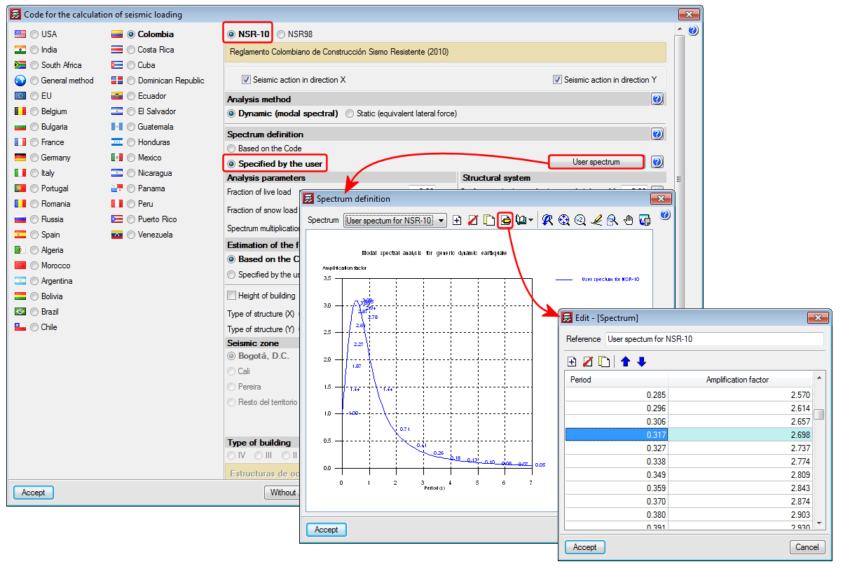
This code was already implemented in previous CYPECAD and CYPE 3D versions. Now, in the 2015.f version the possibility has been added to define a user seismic spectrum.

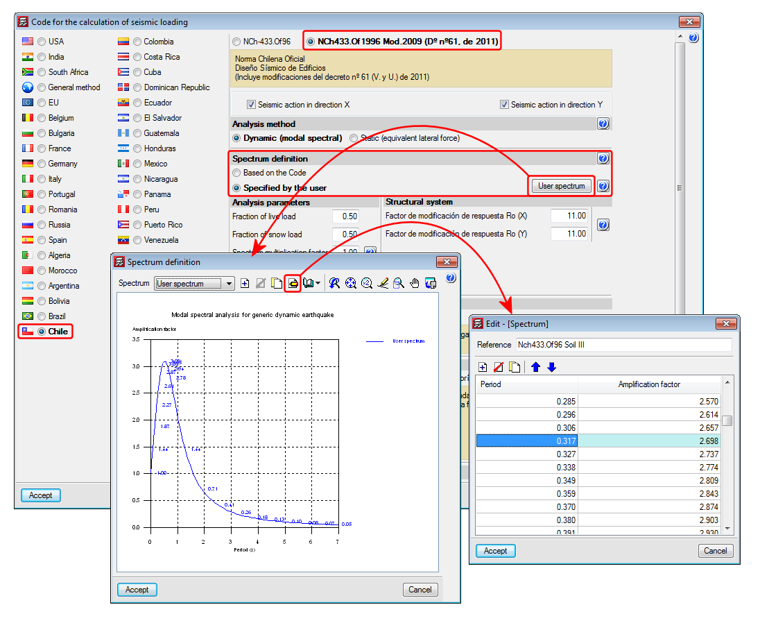
A design spectrum must be defined to carry out a seismic analysis of the structure. Each earthquake-resistant code provides the criteria that are to be applied within a specific territory when considering seismic action in a project. Nonetheless, users may opt to, under their responsibility, apply other criteria to those established in the code. The program offers, for this seismic code, different ways to proceed, to contemplate both possibilities. The seismic spectrum can be:

  • Calculated in accordance with that specified in the seismic code to be applied.
  • Specified by users based on their own criteria.

This code was already implemented in CYPECAD, CYPE 3D and other CYPE programs as of previous versions. Recently, with the 2015.e version, it became part of the group of codes that can be used to carry out punching shear verifications in accordance with code criteria. 

Now in the 2015.f version, when the NTCRC:2004 code of Mexico is selected in CYPECAD as the concrete code, beams are edited with the advanced beam editor and columns with the advanced column editor. This implies important improvements in the application of these codes:

  • Detailed U.L.S. and S.L.S. check reports for concrete beams and columns (including torsion checks)
  • U.L.S. and S.L.S. reports for steel beams and columns
  • Diagrams and numerical values for necessary and effective steel areas
  • Bar bending diagrams and reinforcement layout configurations in frame drawings
  • Design of variable depth concrete beams
  • And, generally, provides a quick and comfortable graphical interface to edit the resistant elements of the frame (reinforcement bars, lattices etc.)

If a seismic analysis is carried out, the NTCRC:2004 code is compatible with a group of seismic codes, but it is only with the NTC-2004 code that the advanced column and beam editors of CYPECAD can be used and take into the account its criteria for the capacity design in the design of concrete columns and beams.

More information can be found in the section on the “Advanced beam editor” of CYPECAD in the concrete beams webpage. 

The concrete and seismic codes for which CYPECAD takes into account capacity design criteria for concrete columns and beams can be seen in the “Capacity design criteria for seismic design of concrete columns and beams” section of the CYPECAD webpage. 

More information can be found in the section on the “Design codes available for use with the Advanced beam editor” in the webpage dedicated to concrete beams in CYPECAD. 

In the section on “Programs which generate U.L.S. check reports”, more information can be found on the codes that are available for CYPECAD’s advanced column editor. 

The precision of the window in which the elevation difference of the connections is defined, has been increased to 1mm. In previous versions it was limited to 5mm.

The possibility to separately define the reinforcement loss for instantaneous and differed post-tensioned slabs has been added. Therefore, when analysing, two post-tension loadcases will appear: one with instantaneous losses and another with total losses (instantaneous + differed). A new combination will also appear in the combinations in which the initial post-tension loadcase will act with the self-weight of the structure, so the post-tensioning without any loading, one of the most critical steps when tensioning the tendons of the floor slab, can be controlled.

New assembly reinforcement and skin reinforcement design options have been implemented and can be used in jobs for which the concrete and seismic (if applicable) codes allow for the use of the advanced beam editor. 

Assembly reinforcement design options

A new option “Only provide anchorage hooks in secondary beams if necessary” has been implemented. This option is active by default, and so has the same effect as in previous versions. If the option is deactivated, the assembly reinforcement hook will always be provided at secondary beams.

Skin reinforcement design options

A series of design options for skin reinforcement have been implemented. In previous versions, users could only indicate as of which beam depth the skin reinforcement was to be placed, and once placed, the maximum spacing it was to have for floor slabs and beams in floor slabs and foundations had to be defined. Now these options can be edited by selecting the “Minimum reinforcement” button (skin reinforcement dialogue box – see image). Additionally, three new options have been implemented:

  • Minimum steel area
    Allows users to specify the minimum skin steel area at each side of the beam. If the steel area indicated by the design code is greater than that indicated in the option, the program will apply the greatest value.
  • Anchorage length
    Allows users to anchor skin reinforcement as of the internal face of the column where the dimension of the column in that direction is greater than a user specified value . For other cases, the skin reinforcement will be anchored as of the column axis. This option avoids having to provide excessive anchorage lengths in wide columns.
  • Minimum anchorage length
    Allows users to indicate the minimum anchorage length for the skin reinforcement. The program will check the minimum length indicated by the code and will apply the greater of the two.

Frame drawing improvements

The frame drawings in the advanced beam editor have been improved when the option to draw larger bars further away has been activated.

Norma Chilena Oficial Diseño Sísmico de Edificions (Includes modifications of decree n° 61 (V. and U.) of 2011).

This code was already implemented in previous CYPECAD and CYPE 3D versions. Now, with the 2015.e version, a user seismic spectrum can be defined. A design spectrum must be defined to carry out the seismic analysis of the structure. Each seismic resistance code provides the criteria that are to be followed within a specific territory for the seismic action to be considered in the project. Nonetheless, the project designer can adopt, under his/her responsibility, different criteria to that established in the code. The program offers different ways to proceed for the use of either way. The design seismic spectrum can be:

  • Calculated in accordance with that specified in the seismic code to be applied.
  • Specified by users based on his/her criteria.

Diseño estructural. Cargas de viento.

Implemented in CYPECAD.

  • BAEL-91 (R-99) (France)
    Fascicule n°62 – Titre I- Section I Règles techniques de conception et de calcul des ouvrages et des constructions en béton armé suivant la méthode des états limites – BAEL 91 révisé 99.
  • NTCRC:2004 (Mexico)
    Normas técnicas complementarias del reglamento de construcciones para el Distrito Federal

These codes were already implemented in CYPECAD, CYPE 3D and other CYPE programs as of previous versions. Now, in the 2015.e version, these codes are implemented in “Punching shear verification” and hence, also in the punching shear check carried out by CYPECAD in accordance with code criteria. This check was implemented in CYPECAD in the 2015.a version and, since then, coexists with the tangential stress check.

Complete and trim punching shear perimeter

Two options have been implemented which allow users to modify the punching shear perimeter calculated by the program (Results > Flat/Waffle slabs > Punching shear):

  • Complete perimeter

    Allows users to draw the punching shear perimeter on zones at which it has been trimmed by the analysis or manually.
  • Trim perimeter

    Allows users to trim the punching shear perimeter of a column.

Users can use the “Regenerate perimeters” option (Results > Flat/Waffle slabs > Punching shear) to eliminate any modifications carried out on the punching shear perimeters.

Punching shear check at supports with adjacent dropped beams

The option “Supports to which dropped beams reach” has been implemented (Job > General data > By position button > Slab options > Punching shear) which does not allow the punching shear check to take place at a support if the ratio between the depth of the dropped beams adjacent to the support and the depth of the slab is greater than the value defined in this option. The default value for this ratio is 1.20.

Improvements of the codes indicated below have been implemented or included in the application. Detailed information can be found in the previous sections:

  • Concrete code
    • CIRSOC 201 2005 (Argentina) and IS 456: 20000 (India)
  • Code regarding loads on structures. Seismic loads
    • CIRSOC 103-2013 (Argentina)
    • CHOC-08 (Honduras)
    • NTC 1997 (Mexico – Guadalajara)
  • Fire safety. Fire resistance of the structure
    • ABNT NBR 15200:2012 (Brazil)

Projeto de estruturas de concreto en situação de incêndio.

Implemented in the “Fire resistance check” module and checks the fire resistance and designs the protective coatings for beams, floor slabs, columns, concrete shear walls and walls using the tabular method defined in this code.

With this code, the “Fire resistance check” module carries out the following checks and designs:

  • For the indicated structural elements for which a protective coating can be defined, the program designs the minimum thickness of the protective coating so that the requirements of the applied code are met.
  • For the indicated structural elements for which a protective coating can be defined, the program checks the element with the assigned fire resistance data.
  • If a coating is assigned to a structural element and the program verifies it is not needed to meet the requirements stated in the corresponding code, the program will indicate the coating of the structural element is not necessary, and so the minimum thickness of the coating will be applied for construction reasons.

Users must have the “Fire resistance check” module to be able to carry out these checks, as well as the corresponding aforementioned structural elements.

The fire resistance check in CYPECAD is activated in the “General data” dialogue box (Job > General data). Upon activating it, a dialogue box opens where users can define the required resistance, the compartmentation of the floors (with or without compartmentation) and the coatings of the construction elements. If users wish to use the “ABNT NBR 15200:2012” fire resistance code, the “ABNT NBR 6118:2014” or “ABNT NBR 6118:2007” concrete code must be selected in CYPECAD.

The corresponding Brazilian code required to carry out the fire resistance checks of steel beams and columns in CYPECAD and steel sections in CYPE 3D will be implemented in upcoming versions.

Normas Técnicas Complementarias para Diseño por Sismo para Guadalajara 1997.

Implemented in CYPECAD and CYPE 3D.

CYPE Mentor