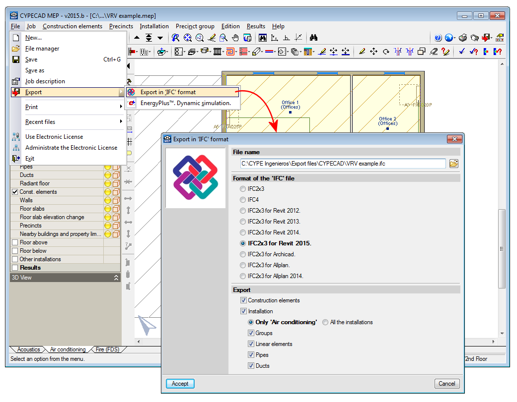
Update history​​

CYPECAD

The 2015.b version of CYPECAD incorporates the Rumanian seismic code: P100-1/2013 and application improvements of the Argentinian CIRSOC 103-2008 code regarding the calculation of the Fundamental period of the structure.

More information can be found in the section: Code regarding loads on structures. Seismic loads.

The 2015.b version of CYPECAD incorporates the ACI 318M-08 (USA), Nch430.Of2008 (Chile), NTE E.060: 2009 (Peru) and NSR-10 (Colombia) codes to carry out the punching shear verification in accordance with these codes.

More information on this implementation.

Normas Argentinas para Construcción Sismorresistente. Proyecto de Reglamento CIRSOC 103, Parte I: Construcciones en general.

This code was already implemented in CYPECAD and CYPE 3D as of previous versions. Now, with the 2015.b version, CYPECAD has two options to indicate the Fundamental period of the structure (used to calculate the base shear):

  • Based on the code
    This was the only way possible for this code in previous versions.
  • Specified by the user
    Implemented in the 2015.b version for this code, although it was available for other codes as of previous versions.

More information on the Fundamental period of the structure can be found here.

Cod de proiectare seismică P100, Partea 1 - P100-1/2013

Implemented in CYPECAD and CYPE 3D.

  • ACI 318M­08 (USA)
    Building Code Requirements for Structural Concrete.
  • Nch430.Of2008 (Chile)
    Norma Chilena oficial NCh430.Of2008.
  • NTE E.060: 2009 (Perú)
    Reglamento Nacional de Edificaciones. Norma E.060 Concreto Armado (2009).
  • NSR­10 (Colombia)
    Reglamento Colombiano de Construcción Sismo Resistente NSR-10. Título C - Concreto estructural.

These design codes were already implemented in CYPECAD, CYPE 3D and other CYPE programs as of previous versions. Now, with the 2015.b version, the codes have been implemented in “Punching shear verification” and hence, also in the punching shear verification carried out by CYPECAD. This check was implemented in CYPECAD in the previous version (2015.a) and coexists since then with the tangential stress check.

Integration and coexistence with the point tangential stress check

Punching shear verification, was implemented in the 2013.e version. This program was designed to operate as an independent program (within the Structures group of the main CYPE program menu) and as a tool within CYPECAD. Since the 2013.e version, it has only operated as an independent program until now, in the 2015.a version, where it has been implemented to work within CYPECAD .

Punching shear verification checks the Failure Limit State of concrete for punching shear in flat and waffle slabs exposed to concentrated loads from rectangular or circular supports (in both the independent program and in CYPECAD). The program can check slabs with or without transverse punching shear reinforcement (reinforcement inclined at 45º or beam-type reinforcement), takes into account the presence of openings or lightweight zones in the slab, and the position of the supports (by indicating whether it is an internal, edge or corner support in the independent program and by the geometry of the floor slab in CYPECAD).

In CYPECAD, the Failure Limit State check for punching shear is also carried out on mat foundations.

By integrating “Punching shear verification” in CYPECAD as of the 2015.a version, the ultimate limit state check for punching shear in accordance with code criteria has been incorporated. Nonetheless, the point tangential stress check carried out up to now in CYPECAD remains, as does the design of the transverse reinforcement in accordance with the same check criteria.

  • Point tangential stress check (punching shear for versions before the 2015.a version)

    A tangential stress verification is carried out on surfaces which are concentric to the perimeter of the support, between a distance of half the depth of the slab from the support and at intervals of 0.75 times the depth of the slab. The value of the tangential stress at the intersection points of the mesh with the punching shear perimeter is obtained using the shears at the nearby nodes by means of linear interpolation. This stress is compared to the maximum punching shear tangential stress resistance, which is calculated using the corresponding concrete code. This approach, based on point tangential stress checks at the mentioned perimeters, is different to the punching shear failure check provided by different concrete codes.
  • Punching shear in accordance with code criteria (implemented in CYPECAD as of the 2015. Version).
    In general, design codes use a nominal tangential stress within a critical surface area which is concentric to the loaded zone, and is calculated taking into account the reaction of the support and the moments it transfers to the slab.

The punching shear analysis method in accordance with code criteria is a simplification proposed by different codes; which also allow for the use of, as alternative method, procedures which provide a more precise evaluation of the tangential stress at surface areas which are concentric to the perimeter of the support, which is the case of the tangential stress check method carried out in CYPECAD as of earlier versions.

Therefore, the final result obtained by both procedures may not coincide, even though both are valid.

The reinforcement calculated by CYPECAD, depending on the point tangential stress, can be used as a reference to introduce punching shear reinforcement (reinforcement at 45º angles or beam-type reinforcement). Once introduced, CYPCAD automatically checks the reinforcement that has been provided by carrying out a punching shear verification in accordance with code criteria. If punching shear reinforcement is provided, the tangential stress reinforcement located within the surface area concentric to the support and limited by the critical punching shear perimeter, must be deleted to avoid it being duplicated in drawings and job quantities. To do so, a tool has been included in CYPECAD (as well as other new options in the punching shear dialogue box) which allows for users to eliminate the tangential stress reinforcement .

Operation of the punching shear check in CYPECAD

During the analysis of the job, CYPECAD checks the point tangential stress on flat and waffle slabs and mat foundations. If necessary, CYPECAD designs the transverse reinforcement (vertical bars) in accordance with the same criteria. If users wish so, they can carry out the punching shear check and, if required, provide transverse punching shear reinforcement (bars inclined at 45º or beam-type reinforcement) which will substitute those that have been obtained using the tangential stress check and lie within the critical punching shear perimeter of the support that has been checked.

A series of options have been implemented in the “Punching shear” dialogue box (Results > Flat/Waffle slabs > Punching shear) to carry out the punching shear check and provide the required reinforcement:

  • Views
    Using this option, users can select the flat and waffle slab reinforcement to be seen on screen.
  • Checks
    Allows users to view on screen, print or export (Text, HTML, PDF, RTF, DOCX) all the Failure Limit State checks for punching shear carried out by the program at the selected support.
  • Union of overlapping critical perimeters
    This option creates the union of the intersecting critical perimeters of the supports.
  • Select and join critical perimeters
    This option joins two or more critical perimeters.
  • Separate joined critical perimeters
    This option separates critical perimeters which had previously been joined.
  • Regenerate perimeters
    The program obtains the perimeters each time the job is analysed and when there significant data changes which may affect its composition. This is not carried out for other types of changes, such as when the width of a beam has been modified. Users can use this option, if deemed necessary, after having carried out this type of changes.
  • Edit
    Having selected a support, this option opens a dialogue in which all the data that has been obtained automatically by CYPECAD is displayed, so it can be modified by users (effective depth of the slab, depth available for punching shear reinforcement, slab tensile reinforcement area).

    An additional area “Asw” (cm2/m) of punching shear reinforcement and a normal concrete stress (kp/cm2) can also be added. For example, the section of transverse reinforcement of a beam (cm2/m) which lies within the zone contained by the critical punching shear perimeter is not taken into account automatically by the program (with regards to punching shear reinforcement) but, by consulting it using CYPECAD’s advanced beam editor (Results > Beams/Walls > Edit beams), it can be included in the “area of punching shear reinforcement (Asw/s)” field of the edit dialogue of the support selected using this option.

    All the data defined here is used to generate the critical perimeter and carry out the punching shear resistance checks.
  • Delete reinforcement placed by tangential stress
    T he reinforcement calculated by the program due to point tangential stress can be used as a reference to introduce punching shear reinforcement (bars inclined at 45º angles or beam-type reinforcement) and then carry out a punching shear verification in accordance with code criteria. In this case, the tangential stress reinforcement located within the critical punching shear perimeter should be deleted. This reinforcement can be deleted using this option and so avoid duplicating it on drawings and job quantities.
  • Eliminate panels
    This option allows users to select panels for which punching shear checks are not to be carried out.
  • Generate reinforcement
    This option allows users to introduce two orthogonal reinforcement configurations at a support.
  • Add reinforcement
    Users can add reinforcement in any direction and at any support.
  • Edit reinforcement
    Allows users to edit punching shear reinforcement introduced at a support.
  • Assign reinforcement
    Using this option, users can introduce reinforcement bars equal to other reinforcement that is already present.
  • Delete reinforcement
    Deletes the selected reinforcement.

Punching shear reinforcement quantities and drawings

A new drawing, “Punching shear reinforcement bars” has been implemented (File > Print > Job drawings > add a drawing > select “Punching shear reinforcement bars” drawing). A plan view of the floor displaying the punching shear reinforcement provided by users, the detailing, take-off table and quantities summary are all displayed in this drawing.

The punching shear reinforcement quantities are also contained in the takeoff report (File > Print > Job report > Job takeoffs).

Codes implemented for the punching shear check

The concrete codes for which the punching shear check is available in CYPECAD for the 2015.a version are:

  • ABNT NBR 6118:2014 (Brazil)
    Norma Brasileira ABNT NBR 6118 (2014). Projeto de estruturas de concreto - Procedimento.
  • ABNT NBR 6118:2007 (Brazil)
    Norma Brasileira ABNT NBR 6118 (2007). Projeto de estruturas de concreto - Procedimento.
  • Eurocode 2
    The adapted codes for each country include their corresponding national application document.
    • Eurocode 2 (EU)
      EN 1992-1-1:2004/AC 2008. Design of concrete structures. Part 1-1: General rules and rules for buildings.
    • Eurocode 2 (France)
      NF EN 1992-1-1 :2005/NA: Mars 2007. Calcul des structures en béton. Partie 1-1 : Règles générales et règles pour les bâtiments.
    • Eurocode 2 (Portugal)
      NP EN 1992-1-1:2010/NA. Projecto de estructuras de betão. Parte 1-1: Regras gerais e regras para edifícios.
  • EHE-08 (Spain)
    Instrucción de Hormigón Estructural.
  • NTC: 14-01-2008 (Italy)
    Norme tecniche per le costruzioni.

Required license permits

For CYPECAD to be able to perform the punching shear check in accordance with code criteria, the user license must have the required permits to use the “Punching shear verification” program. Additionally, the user license must include, at least, the permits required to design the type of floor slab where the punching shear check is to be carried out (flat slabs, waffle slabs or mat foundations).

Norma Brasileira ABNT NBR 6118 (2014). Projeto de estruturas de concreto - Procedimento.

This Brazilian concrete code, which entered into force on the 29th May 2014, has been implemented in CYPECAD and other CYPE software programs of the 2015.a version.

Norma Brasileira ABNT NBR 6118 (2014). Projeto de estruturas de concreto – Procedimento.

Implemented in CYPECADCYPE 3D (Metal 3D), Punching shear verification, Stairs, Flat slabs, Corbels, Great depth beams, Foundation elements and Continuous beams.

Eurocode 2: Design of concrete structures. SR EN 1992-1-1:2004/AC

This code was already implemented in CYPE programs as of previous versions.

Now, with the 2014.m version, when Eurocode 2 (Romania) is selected in CYPECAD, columns and beams are edited using their corresponding advanced editors.

More information on CYPECAD’s advanced column editor. 

More information on CYPECAD’s advanced beam editor. 

If a seismic analysis is carried out, Eurocode 2 (Rumania) is compatible with a group of seismic codes which allow for the advanced beam and column editors to continue to be used, and take into account the capacity design criteria for concrete columns and beams:

  • Eurocode 8 (EU)
    EN 1998-1. Eurocode 8: Design of structures for earthquake resistance – Part 1: General rules, seismic actions and rules for buildings
  • 1997 UBC (USA)
    Uniform Building Code
  • 2009 IBC (USA)
    International Building Code

The following codes, used in the “Floor slab sheet editor for precast, reinforced and prestressed joists” for Mexico have been implemented in the 2014.l version:

  • NTCRC: 2004 (Mexico)
    Normas técnicas complementarias para diseño y construcción de estructuras de concreto.
    Used in Mexico City.
  • ACI 318M-08 (USA)
    Building Code Requirements for Structural Concrete (ACI 318M-08).
    Used in the rest of Mexico.

CYPE’s “Floor slab sheet editor” is a free software program. The program is included in the CYPE program installation DVD. It is available in Spanish for Mexico and Spain, in Catalan and in Portuguese for Brazil and Portugal. The file which installs the program is located in the “Install individual programs” directory of the installation folder of any of the indicated languages. Please recall, that when the complete CYPE program version is downloaded from the download area of our website, it consists of a compressed file containing the CYPE software installation DVD. 

CYPE’s “Floor slab sheet editor” is used to introduce data sheets for precast, reinforced and prestressed joist floor slabs that are not included in CYPECAD. The “Floor slab sheet editor” generates an FVA format file which CYPECAD can import and then use the floor slab data sheets that have been introduced in the editor. This is a very useful tool for users wishing to analyse and design projects containing precast, reinforced or prestressed joist floor slabs not included in the program (if they have been provided with data sheets from the manufacturers), and for manufacturers wishing to provide CYPECAD users with the properties of the precast, reinforced or prestressed joist floor slabs so they may be used in their projects (if the manufacturers’ joist floor slabs are not included in CYPECAD).

More information can be found on the “Floor slab sheet editor for precast, reinforced and prestressed joists” on our Spanish webpage (Download, Installation, Data introduction...). 

 A link is also available on the same webpage to download a compressed file to install CYPE’s “Floor slab sheet editor for precast, reinforced and prestressed joists” individually for the indicated languages.

SR EN 1991-1-4/NB (2007) Eurocode 1: Actions on structures. Part 1-4: General actions – Wind actions. National annex (SR EN 1991-1-4/NB).

Implemented in CYPECAD.

The 2014.j version includes two options to define the end of each column span in a different manner when exporting the CYPECAD job to IFC (Industry Foundation Classes) format:

  • The end of the column is situated at the bottom surface of the floor slab or beam of the floor above.
  • The end of the column is situated at the top surface of the floor slab or beam of the floor above.