The 2013.m version of CYPE programs incorporates the generic export to IFC4 format (Industry Foundation Classes) in CYPECAD and CYPECAD MEP. More information on this new feature can be found in the Export to IFC4 format from CYPECAD and CYPECAD MEP section on this webpage.


Seismic analysis. Automatic calculation of the number of vibration modes
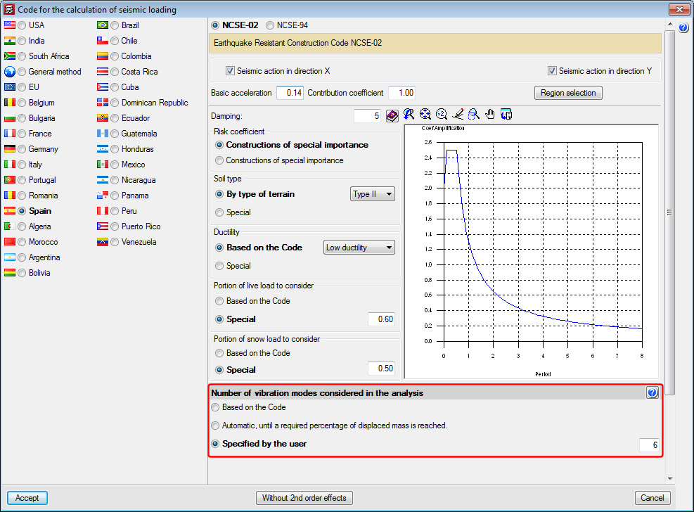
A new section has been implemented within the dialogue box where the selected seismic code parameters are defined (Job > General data > Select With seismic loading > Choose a seismic code): Number of vibration modes considered in the analysis. Here, the program offers different ways to establish the number of vibration modes to be considered in the seismic analysis of the structure:
- Based on the Code
The analysis is carried out in accordance with that specified in the selected seismic code. This section may not exist if the selected seismic code does not specify this data. - Automatic, until a required percentage of displaced mass is reached
Users define the minimum percentage of accumulated modal mass that is required to be displaced in each direction. - Specified by the user
Users indicate the number of vibration modes based on their own judgement. Until now, this was how the number of vibration modes was indicated for the seismic analysis, where users had to choose the value bearing in mind the requirements of the selected code, the structure to be analysed and/or their own considerations.
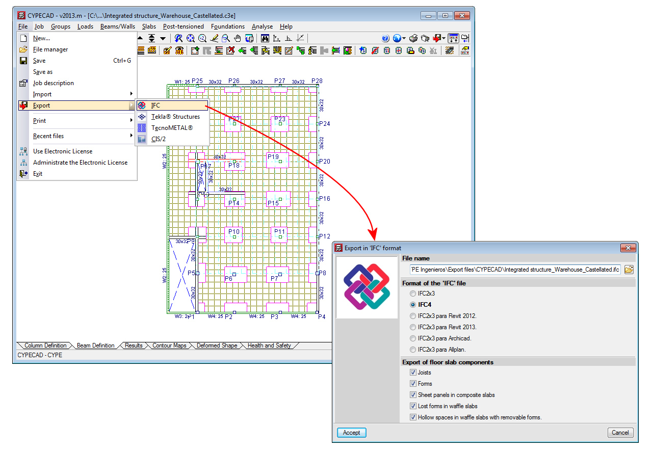
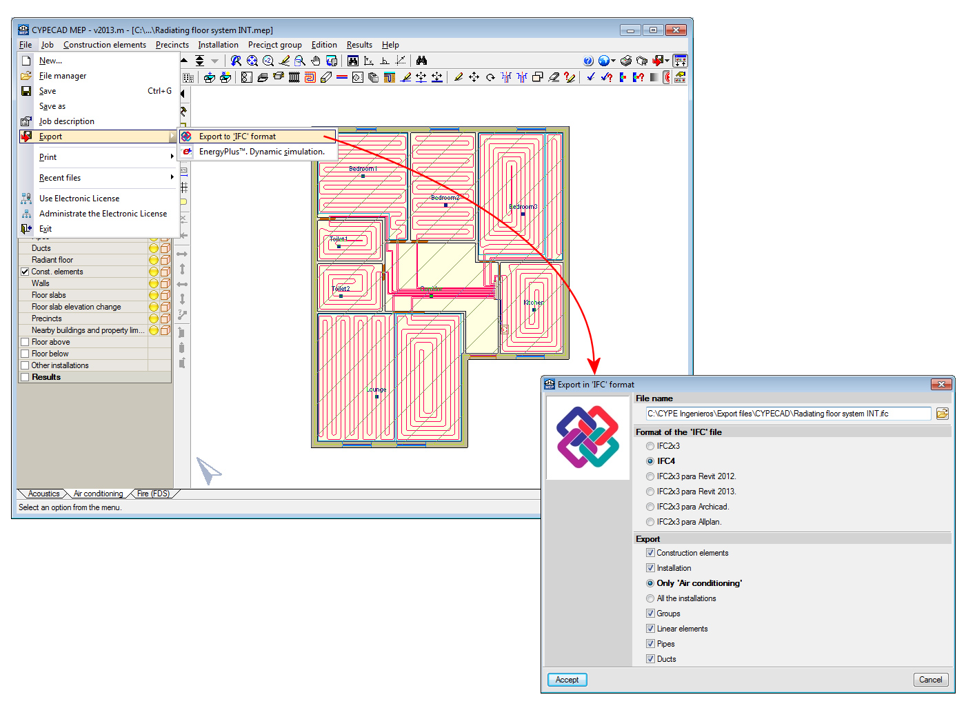
Export to IFC4 format from CYPECAD and CYPECAD MEP
The 2013.m version of CYPE programs incorporates the generic export to IFC4 format (Industry Foundation Classes) in CYPECAD and CYPECAD MEP. This way, CYPE programs have become the first engineering and construction software to export to IFC format with the specifications of the new definitive version: IFC4 (previously known as IFC 2x4).
CYPECAD and CYPECAD MEP currently allow for the export to IFC in the following formats:
- IFC2x3
- IFC4
- IFC2x3 for Revit 2012
- IFC2x3 for Revit 2013
- IFC2x3 for Archicad
- IFC2x3 for Allplan
As Revit, Archicad and Allplan gradually incorporate reading of the IFC4 format in their software, CYPECAD and CYPECAD MEP will incorporate specific exports to these programs in IFC4 format.
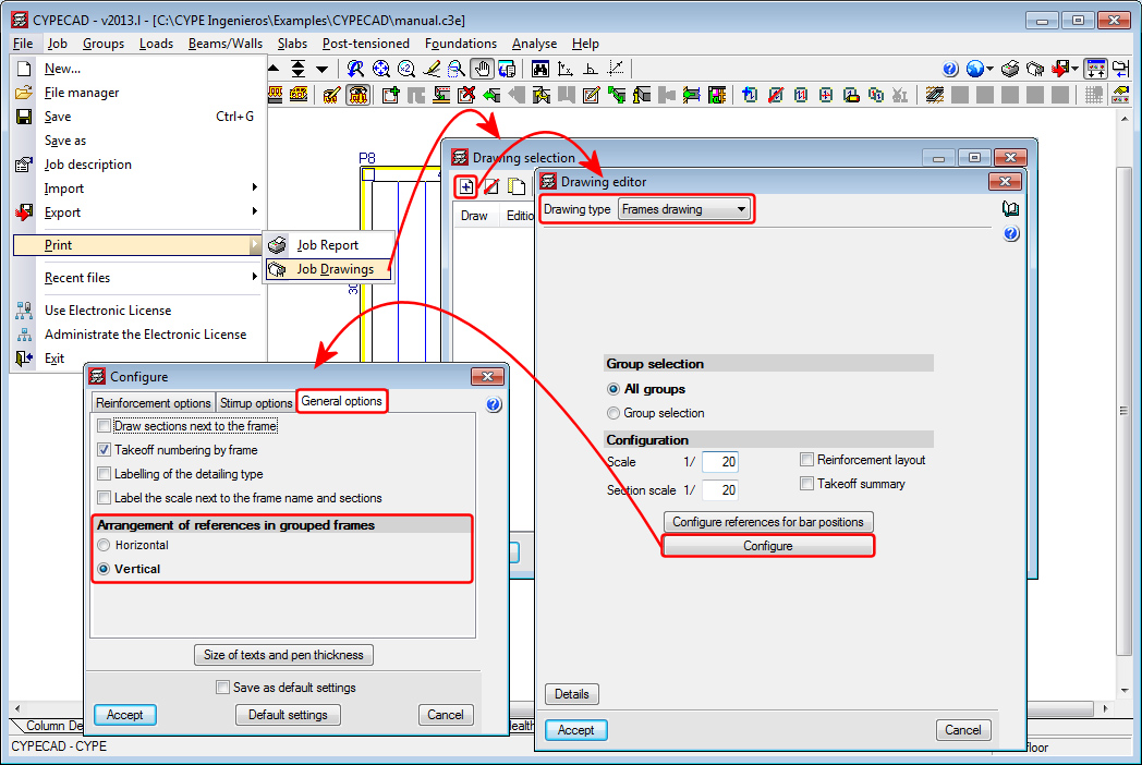
Layout configuration of the grouped frame references in the frames drawings
The option: Arrangement of references in grouped frames (File > Print > Job drawings > Add button > Select Frames drawing in “Drawing type” > Configure button > General options tab) has been implemented, which allows for the references of the grouped frames to be placed next to one another (option: Horizontal) or underneath the preceding reference (option: Vertical).
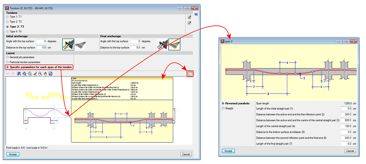
Specific parameters for each span of the tendon
The 2013.l version includes a new option; Specific parameters for each span of the tendon. This option is located in the dialogue in which tendons are edited (Beam Definition tab > Post-tensioned > Edit a tendon). Within this dialogue, users can select three options in the Layout section:
- General job parameters (existing option)
This option displays, at information level, the parameters that have been defined in the Options dialogue box. Upon selecting this option, the general parameters of the job are assigned to the tendons being introduced or under edition. - Particular tendon parameters (existing option)
This option opens a dialogue box where the layout parameters of the tendons being introduced or under edition. By selecting this option, the particular parameters are assigned to those tendons. - Specific parameters for each span of the tendon (new option implemented in the 2013.l version)
Using this option, users can edit each span of the tendon, so different properties can be assigned to the layout of each span. Each span can be defined as curved or straight. If it is defined as curved, the properties of the layout that can be modified are:
- Span length
- Length of the initial straight part
- Distance between the active end and the first inflection point
- Distance between the active end and the centre of the central straight part
- Length of the central straight part
- Distance to the bottom surface at midspan
- Distance between the second inflection pont and the final end
- Length of the final straight part
When this option is selected, and if users place the mouse cursor on a span of the longitudinal section displayed in the edition dialogue box of the tendon, an information box appears indicating the properties of the span. By clicking on it with the left mouse button, these properties can be edited.