Update history​​

CYPECAD

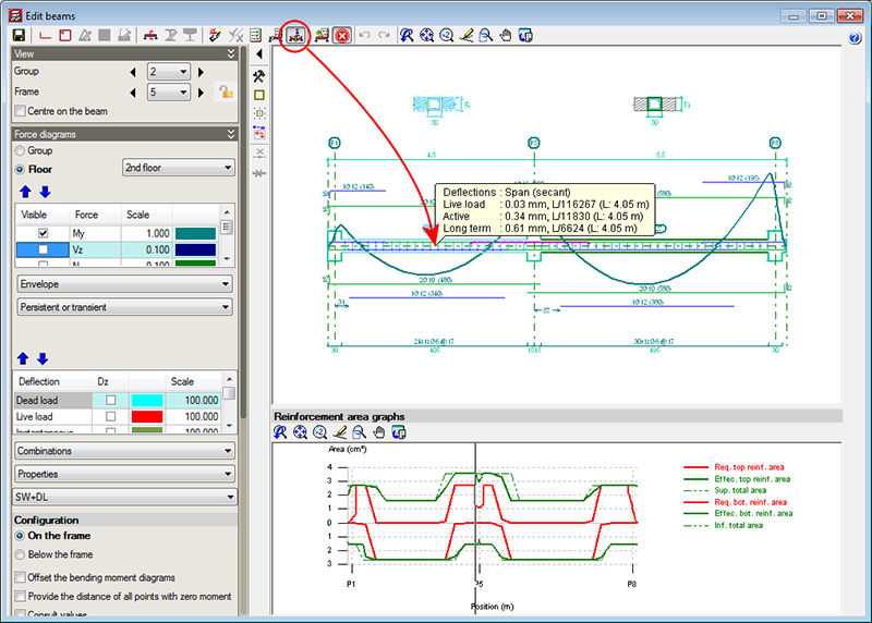
A new option, Consult deflections in spans (represented by the  button in the top part of the beam editor), which displays the deflection values of the selected frame span. This tool provides the same information as is obtained using the “Beam/wall information” option in the “Beams/Walls” menu of CYPECAD.

The Consult deflections in spans option lets users know the deflection of a span without having to leave the beam editor, and takes into account any changes users may have carried out on the frame reinforcement.

The deflection is not calculated each time users change the reinforcement. Users must bear in mind that the deflection calculation process is quite laborious and, if the program were to update the values each time the reinforcement is modified, the reinforcement edition process would be, unnecessarily, very slow. Hence, when the Consult deflections in spans option is used, once changes in the frame reinforcement have been carried out, the program indicates that the span deflections have to be recalculated and asks the user if he/she wishes to continue. If the answer is affirmative, the span deflections will be recalculated and displayed on screen. If the answer is negative, the program will not display the deflection information.

The reinforcement area representation changes automatically and displays the longitudinal reinforcement area when any of the longitudinal reinforcement edition options are selected ( button in the top part of the editor). Similarly, the transverse reinforcement areas are automatically displayed when any of the transverse reinforcement edition options are used ( button in the top part of the editor).

The position of the cursor is represented in the areas graph of the frame by means of a vertical line when the cursor is located in the zone where the reinforcement details of the frame can be viewed, and if any of the following beam editor options have been activated:

  • Introduce assembly reinforcement
  • Introduce additional reinforcement bars
  • Introduce skin reinforcement
  • Introduce stitching reinforcement
  • Introduce overlaps
  • Edit (longitudinal reinforcement)
  • Edit shear reinforcement
  • Divide shear reinforcement spans

This vertical line moves at the same time as the cursor is displaced over the reinforcement details, and aids in recognising the zone in which the work is being carried out.

This feature is also available when the option “Consult values” (of the represented force graphs) is marked, which is located in the “Configuration” section in the lateral menu of the beam editor.

The 2013.e, 2013.g, 2013.h and 2013.i versions of CYPECAD implemented the capacity design criteria for bending and shear for the seismic design of concrete supports, and capacity design criteria for shear for the seismic design of concrete beams in accordance with the following codes: ACI 318M-08 (USA – International), EHE-08 (Spain), NCSE-02 (Spain) and IS 13920:1993 (India).

Now, implemented for the 2013.j version, are the capacity design criteria for bending and shear for the seismic design of concrete supports, and capacity design criteria for shear for the seismic design of concrete beams in accordance with the NSR – 10 (Colombia) code.

Norma Chilena Oficial. Diseño Sísmico de Edificios.

This code was already implemented in CYPECAD and Metal 3D, as of previous versions. As of the 2013.j version, if this code is used together with the NCh430.Of2008 concrete code, users can also use CYPECAD’s advanced beam editor.

Improvements have been implemented in the following seismic codes:

  • NC 46:1999 (Cuba)

Construcciones sismo resistentes. Requisitos básicos para el diseño y construcción.

  • NSR-10 (Columbia)

Reglamento Colombiano de Construcción Sismo Resistente (2010).

These codes were already implemented in CYPECAD and Metal 3D, as of previous versions. They are used in CYPECAD together with the ACI 318M-08 (USA-International) code.

As of the 2013.j version, if users select the ACI 318M-08 (USA International) code and combine it with either of the previously mentioned seismic codes, they can then use CYPECAD’s advanced beam editor.
If the NSR-10 (Colombia) code is combined with the NSR-10 concrete code (Colombia – Título C – Concreto estructural), users can also use CYPECAD’s advanced beam editor.

Construcciones sismo resistentes. Requisitos básicos para el diseño y construcción.

This code was already implemented in CYPECAD and Metal 3D as of previous versions. It is used in CYPECAD together with the ACI 318M-08 (USA – International) concrete code.

As of the 2013.j version, if users select the ACI 318M-08 (USA International) code and combine it with this seismic code, they can then use CYPECAD’s advanced column editor.

Norma Boliviana de Diseño Sísmico (2006). Título A. Análisis y diseño sismo resistente.

Implemented in CYPECAD and Metal 3D.

More information on the implementation of capacity design criteria for the seismic design of concrete columns and beams can be found in the Capacity design criteria for seismic design of concrete columns and beams with the NSR-10 (Colombia) code section of the new features of CYPECAD on this webpage.

Reglamento Colombiano de Construcción Sismo Resistente NSR-10. Título C ‑ Concreto estructural.

Implemented in CYPECADMetal 3DStairsFoundation elements, and Continuous beams.

CYPECAD's advanced column and beam editors are also available with this code.

A new module: Post-tensioned concrete slabs for buildings has been included in the 2013.j version of CYPECAD, which has been created to design the passive reinforcement of post-tensioned slabs before calculating the forces of the post-tensioned tendons (bonded or unbonded) and whose properties have been introduced by program users.

Post-tensioned technology has different degrees of acceptance in many countries. CYPE has designed this module given the increasing demand of CYPECAD users to have a tool which can design post-tensioned concrete slabs.

The Post-tensioned concrete slabs for buildings module allows users to introduce the path of the tendons, their definition, the post-tensioned forces and percentage loss. The program generates a post-tensioned loadcase in which the deviation loads produced by the path of the tendons are introduced. During the slab reinforcement design stage, and if the tendons have been defined as bonded, if there is any capacity excess or shortage regarding the contribution of the active reinforcement, it will be taken into account to establish the passive reinforcement. 

More information on this new CYPECAD module is available here: Post-tensioned concrete slabs for buildings

When exporting to IFC format (Industry Foundation Classes) from CYPECAD (File > Export > IFC), users could select, as of previous versions, amongst four options (IFC 2x3, Archicad IFC 2x3, Revit IFC 2x3, Allplan IFC 2x3). Now, in the 2013.i version, the option for Revit Architecture is split into a further two options: Revit 2012 IFC 2x3 and Revit 2013 IFC 2x3. This way, CYPECAD contemplates the IFC format variations for these two Revit Architecture program versions.

This improvement is also contemplated when exporting to IFC from CYPECAD MEP.

CYPE Mentor