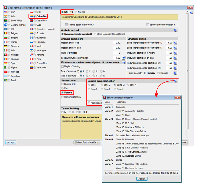
The 2013.e, 2013.g and 2013.h versions of CYPECAD implemented the capacity design criteria for bending and shear for the seismic design of concrete supports, and capacity design criteria for shear for the seismic design of concrete beams in accordance with the following codes: EHE-08 (Spain), NCSE-02 (Spain) and IS 13920:1993 (India).
Now, implemented for the 2013.i version, is the capacity design criteria for bending and shear for the seismic design of concrete supports, and capacity design criteria for shear for the seismic design of concrete beams in accordance with the ACI 318M-08 code.


The capacity design criteria which are currently implemented are:
- For concrete supports:
- Capacity design criteria for bending and shear in accordance with Annex 10 of the EHE-08 code (Spain).
- Capacity design criteria for bending in accordance with NCSE-02 code (Spain)
- Capacity design criteria for shear in accordance with IS 13920: 1993 (India)
- Capacity design criteria for bending and shear in accordance with ACI 318M-08 (USA)
- For concrete beams:
- Capacity design criteria for shear in accordance with Annex 10 of the EHE-08 code (Spain).
- Capacity design criteria for shear in accordance with NCSE-02 (Spain).
- Capacity design criteria for shear in accordance with IS 13920: 1993 (India).
- Capacity design criteria for shear in accordance with ACI 318M-08 (USA).
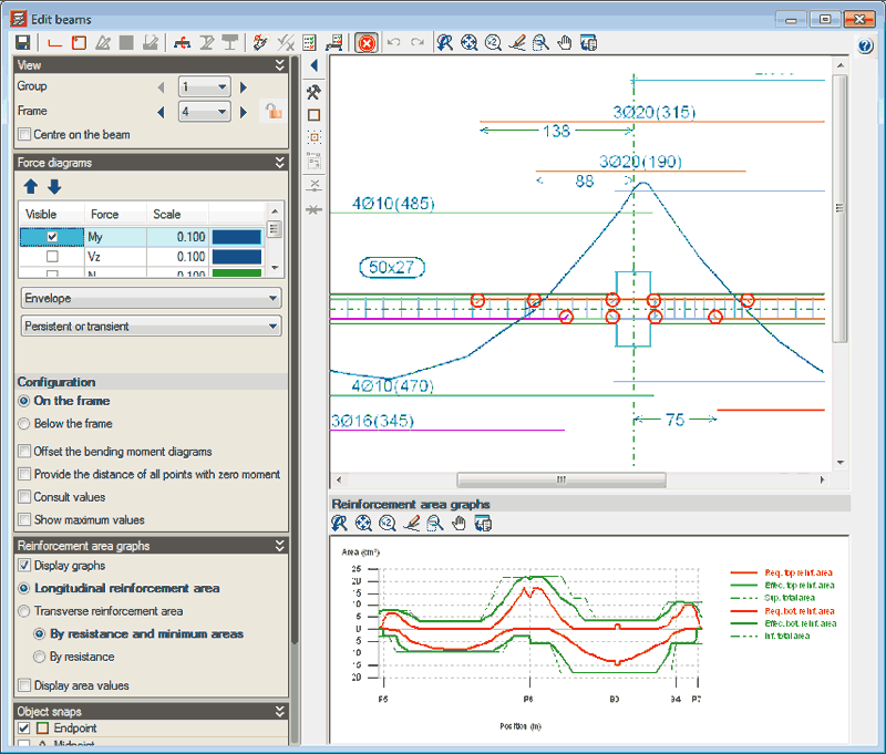
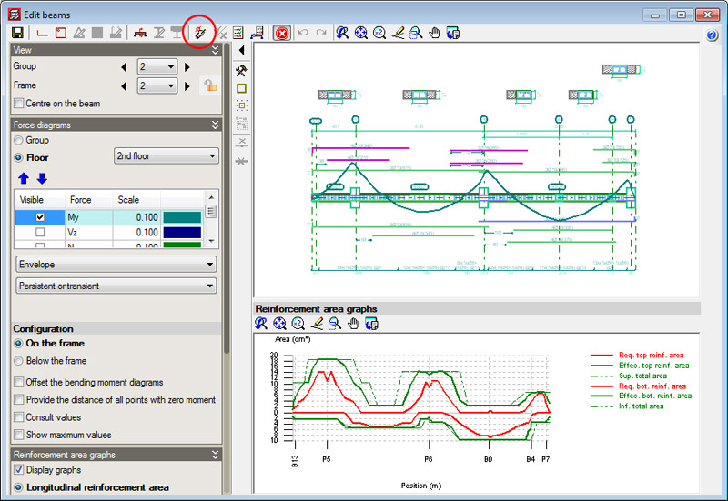
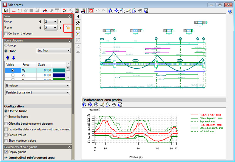
These design criteria are applied in CYPECAD and are specified in the Detailed Ultimate Limit State check reports if the selected codes are those which have been indicated.